
A Matching Algorithm for Underwater Acoustic and Optical Images Based on Image Attribute Transfer and Local Features


Abstract
:1. Introduction
2. Related Work
3. Method
- Based on the analogy of acoustic and optical image attributes, it combines the advantages of CNN depth feature extraction to realize image visual attribute conversion, and then eliminates the differences between the acousto-optic images;
- To match the generated target image and the original image in the acoustic domain and the optical domain, respectively, using the current advanced learned descriptor;
- The data aggregation method is used to display the calibrated matching correspondence on the original acoustic and optical images.
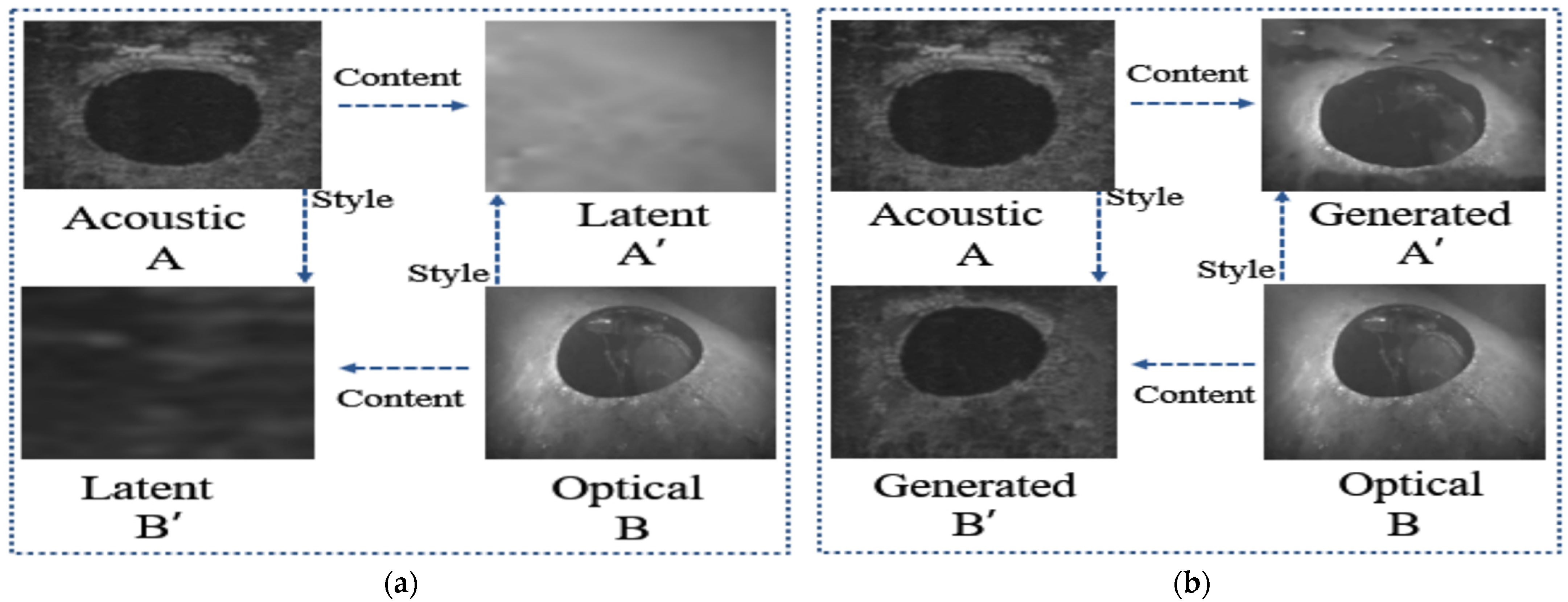
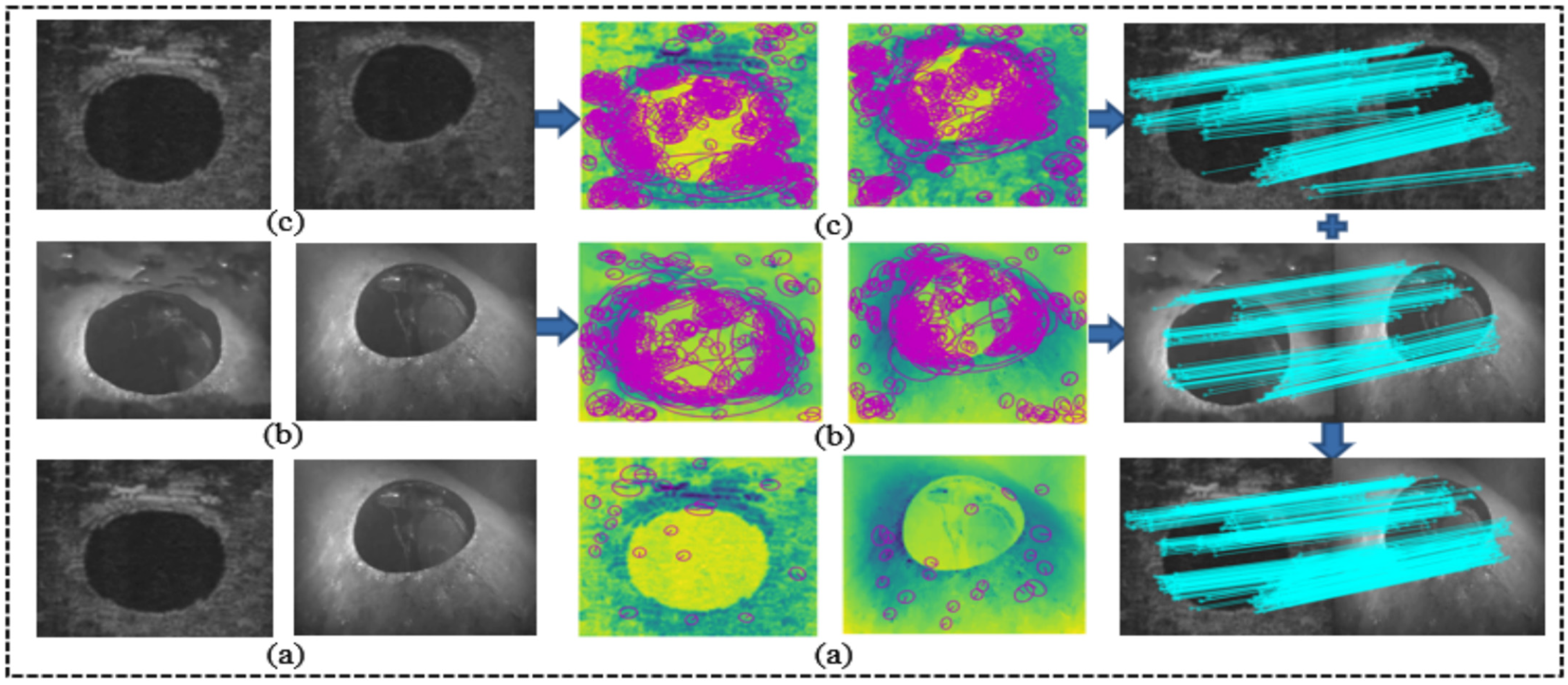
3.1. Image Attribute Transfer
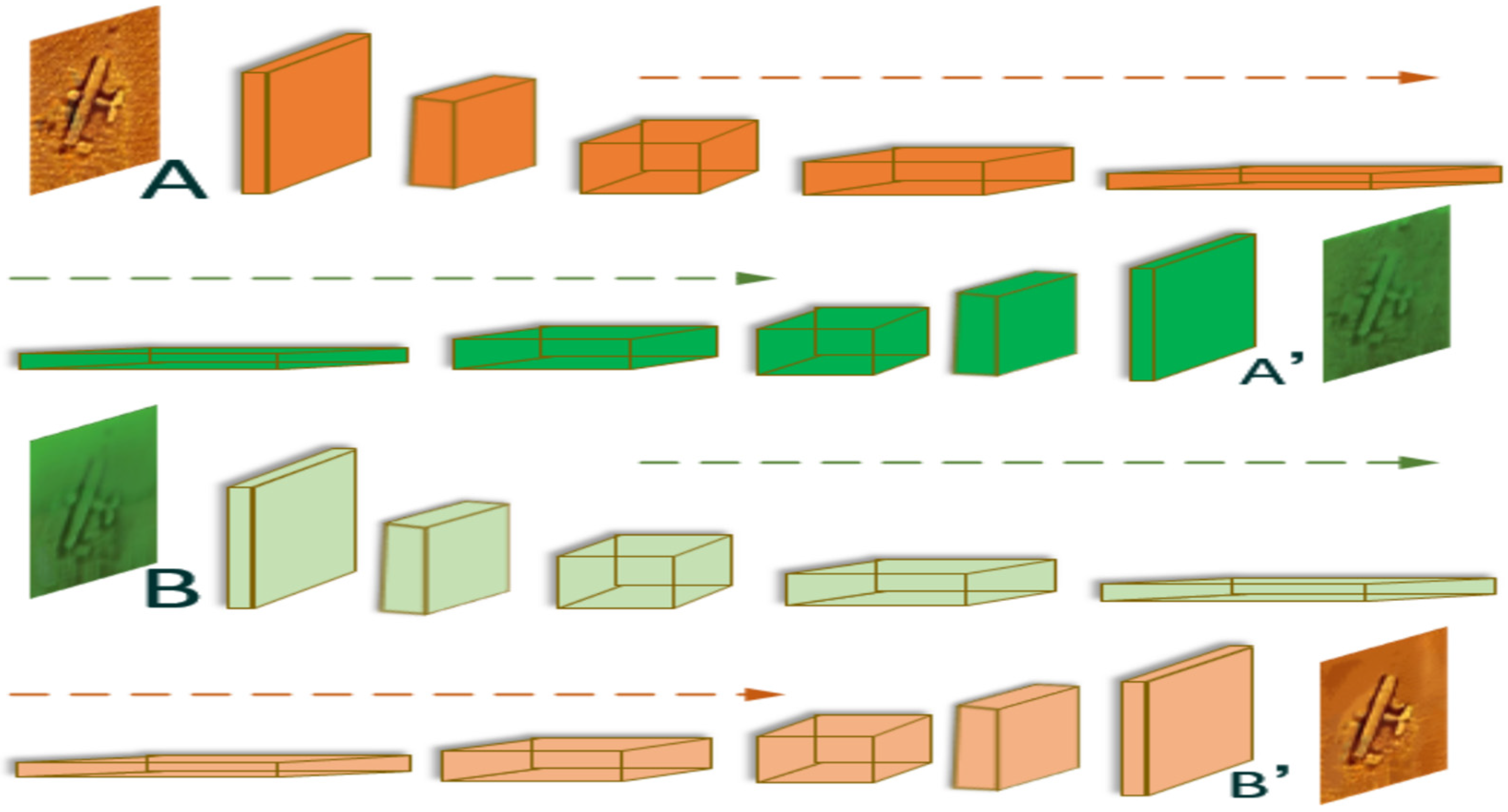
3.1.1. Feature Alignment
3.1.2. Image Reconstruction
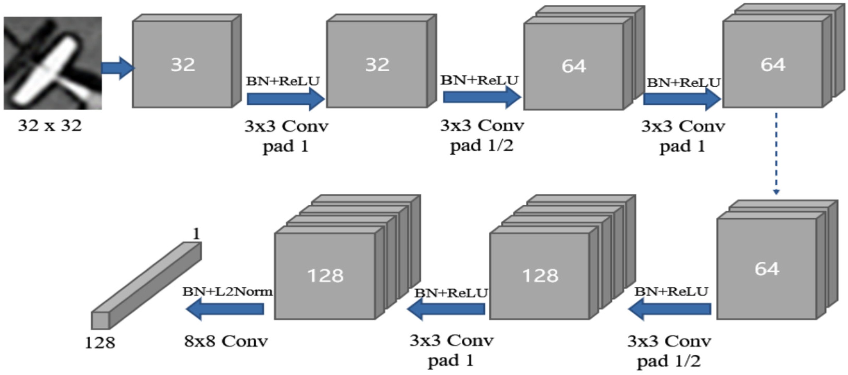
3.2. Learned Descriptor
| Algorithm 1. Underwater acoustic and optical image matching algorithm (UAOM) |
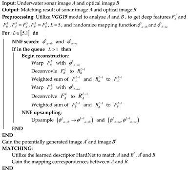 |
4. Experiment
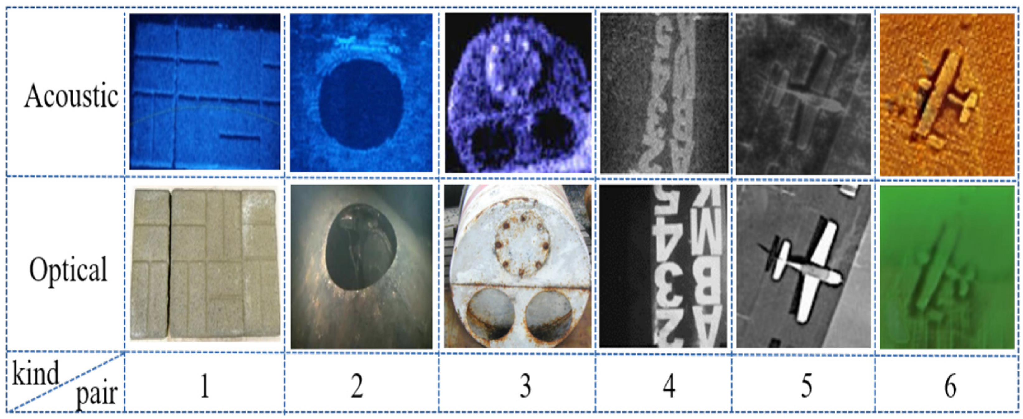
4.1. Test Data Sets
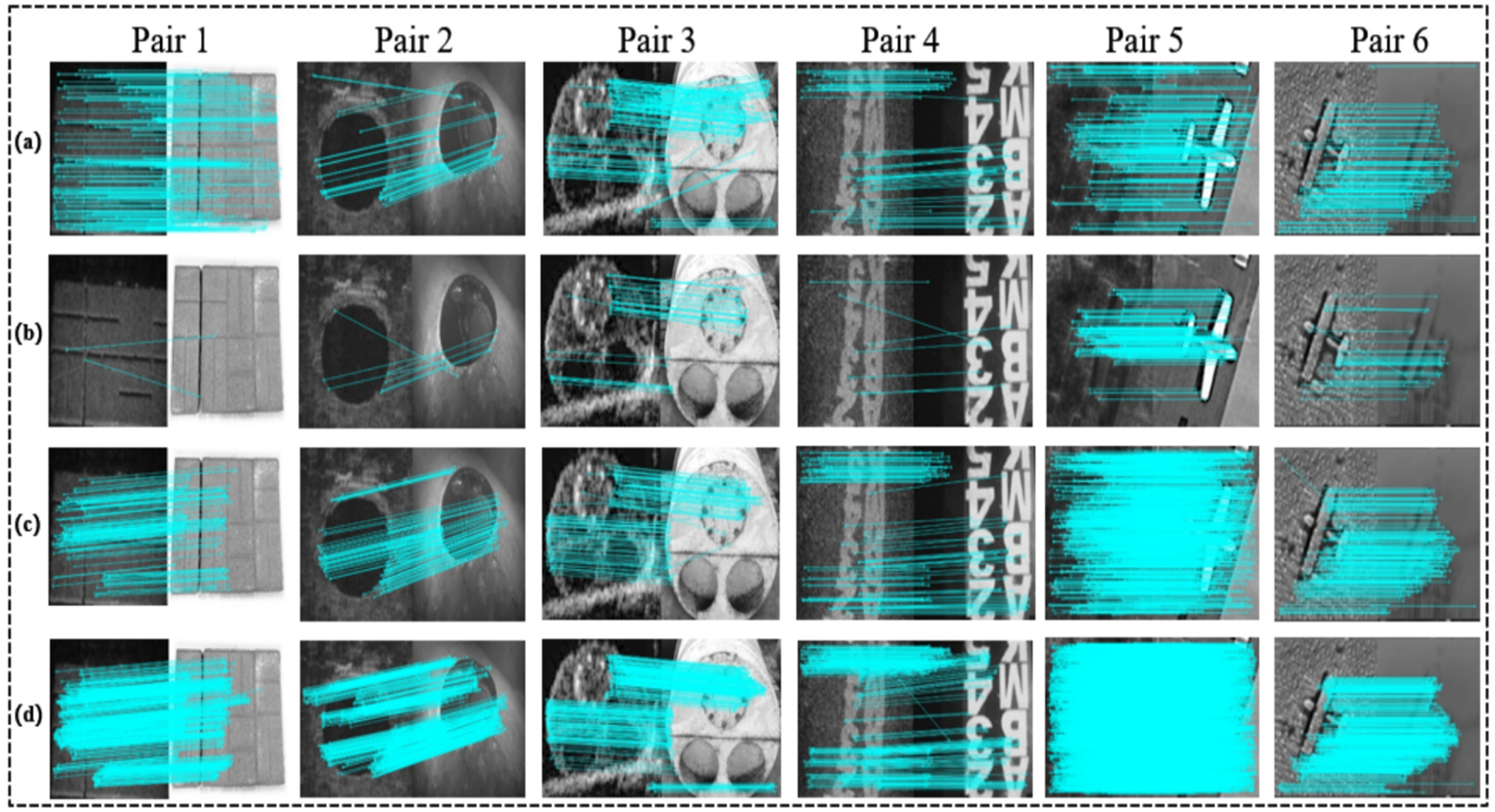
4.2. Experimental Control Groups Sets
5. Results and Evaluation
5.1. Evaluation Indexes Sets
- GM: We adopt the number of good matches in per image pair when the ratio is 0.8 to measure the adaptability robustness of the method. The larger GM obtained for each group of images, the better the performance of the matching method.
- INL: We take the average number of inliers in per image pair when the ratio is 0.8 to reflect the accuracy of the method, the higher the value, the better the performance.
- MA: We introduce the matching accuracy to reflect the effective utilization of our algorithm; MA is numerically equal to the ratio of INL to GM. To a certain extent, MA could reflect the coordination between the detector and descriptor.
- RT: In underwater engineering operations, real-time operation is a fixed requirement, so we introduce RT as the time evaluation index to measure the matching time, so as to verify the complexity of our algorithm.
5.2. Test Tools and Environment Details
5.3. Test and Evaluate Results
6. Discussion
7. Conclusions
Author Contributions
Funding
Institutional Review Board Statement
Informed Consent Statement
Data Availability Statement
Conflicts of Interest
References
- Han, M.; Lyu, Z.; Qiu, T.; Xu, M. A Review on Intelligence Dehazing and Color Restoration for Underwater Images. IEEE Trans. Syst. Man Cybern. Syst. 2018, 50, 1820–1832. [Google Scholar] [CrossRef]
- Kong, W.; Yu, J.; Cheng, Y.; Cong, W.; Xue, H. Automatic Detection Technology of Sonar Image Target Based on the Three-Dimensional Imaging. J. Sens. 2017, 2017, 8231314. [Google Scholar] [CrossRef] [Green Version]
- Tang, X.; Stewart, W. Optical and Sonar Image Classification: Wavelet Packet Transform vs Fourier Transform. Comput. Vis. Image Underst. 2000, 79, 25–46. [Google Scholar] [CrossRef] [Green Version]
- Valdenegro-Toro, M. Object recognition in forward-looking sonar images with Convolutional Neural Networks. In Proceedings of the OCEANS 2016 MTS/IEEE Monterey, Monterey, CA, USA, 19–23 September 2016; pp. 1–6. [Google Scholar]
- Guo, G.; Wang, X.K.; Xu, H. Review on underwater target detection, recognition and tracking based on sonar image. Control Decis. 2018. [Google Scholar] [CrossRef]
- Hurtos, N.; Palomeras, N.; Nagappa, S.; Salvi, J. Automatic detection of underwater chain links using a forward-looking sonar. In Proceedings of the 2013 MTS/IEEE OCEANS, Bergen, Norway, 10–14 June 2013; pp. 1–7. [Google Scholar]
- Vandrish, P.; Vardy, A.; Walker, D.; Dobre, O. Side-scan sonar image registration for AUV navigation. In Proceedings of the 2011 IEEE Symposium on Underwater Technology and Workshop on Scientific Use of Submarine Cables and Related Technologies, Tokyo, Japan, 5–8 April 2011; pp. 1–7. [Google Scholar]
- Liu, J.; Li, B.; Guan, W.; Gong, S.; Liu, J.; Cui, J. A Scale-Adaptive Matching Algorithm for Underwater Acoustic and Optical Images. Sensors 2020, 20, 4226. [Google Scholar] [CrossRef] [PubMed]
- Lowe, D.G. Distinctive Image Features from Scale-Invariant Keypoints. Int. J. Comput. Vis. 2004, 60, 91–110. [Google Scholar] [CrossRef]
- Bay, H.; Tuytelaars, T.; Gool, L.V. SURF: Speeded up robust features. In Proceedings of the European Conference on Computer Vision, Graz, Austria, 7–13 May 2006; pp. 404–417. [Google Scholar]
- Rublee, E.; Rabaud, V.; Konolige, K.; Bradski, G. ORB: An efficient alternative to SIFT or SURF. In Proceedings of the 2011 International Conference on Computer Vision, Barcelona, Spain, 6–13 November 2011; pp. 2564–2571. [Google Scholar]
- Wang, V.T.; Hayes, M.P. Synthetic Aperture Sonar Track Registration Using SIFT Image Correspondences. IEEE J. Ocean. Eng. 2017, 42, 901–913. [Google Scholar] [CrossRef]
- Kim, K.; Neretti, N.; Intrator, N. Mosaicing of acoustic camera images. IEE Proc. Radar Sonar Navig. 2005, 152, 263–270. [Google Scholar] [CrossRef] [Green Version]
- Li, C.; Ye, X.; Cao, D.; Hou, J.; Yang, H. Zero shot objects classification method of side scan sonar image based on synthesis of pseudo samples. Appl. Acoust. 2021, 173, 107691. [Google Scholar] [CrossRef]
- Fusiello, A.; Murino, V. Augmented scene modeling and visualization by optical and acoustic sensor integration. IEEE Vis. Comput. Graph. 2004, 10, 625–636. [Google Scholar] [CrossRef] [PubMed]
- Negahdaripour, S.; Sekkati, H.; Pirsiavash, H. Opti-Acoustic Stereo Imaging, System Calibration and 3-D Reconstruction. In Proceedings of the 2007 IEEE Conference on Computer Vision and Pattern Recognition, Minneapolis, MN, USA, 17–22 June 2007; pp. 1–8. [Google Scholar]
- Huang, B.; Yang, F.; Yin, M.; Mo, X.; Zhong, C. A Review of Multimodal Medical Image Fusion Techniques. Comput. Math. Methods Med. 2020, 2020, 8279342. [Google Scholar] [CrossRef] [PubMed] [Green Version]
- Younggun, C.; Young-Sik, S.; Ayoung, K. Online depth estimation and application to underwater image dehazing. In Proceedings of the MTS/IEEE Oceans 2016 Conference, Monterey, CA, USA, 19–23 September 2016; pp. 1–7. [Google Scholar]
- Cho, Y.; Kim, A. Visibility enhancement for underwater visual SLAM based on underwater light scattering model. In Proceedings of the 2017 IEEE International Conference on Robotics and Automation (ICRA), Marina Bay, Singapore, 29 May–3 June 2017; pp. 710–717. [Google Scholar]
- Li, J.; Skinner, K.A.; Eustice, R.M.; Johnson-Roberson, M. WaterGAN: Unsupervised Generative Network to Enable Real-time Color Correction of Monocular Underwater Images. IEEE Robot Autom. Lett. 2017. [Google Scholar] [CrossRef] [Green Version]
- Hurtós, N.; Cuf, X.; Petillot, Y.; Salvi, J. Fourier-based registrations for two-dimensional forward-looking sonar image mosaicing. In Proceedings of the 2012 IEEE/RSJ International Conference on Intelligent Robots and Systems, Vilamoura-Algarve, Portugal, 7–12 October 2012; pp. 5298–5305. [Google Scholar]
- Li, J.; Kaess, M.; Eustice, R.M.; Johnson-Roberson, M. Pose-Graph SLAM Using Forward-Looking Sonar. IEEE Robot. Autom. Lett. 2018, 3, 2330–2337. [Google Scholar] [CrossRef]
- Valdenegro-Toro, M. Improving sonar image patch matching via deep learning. In Proceedings of the 2017 European Conference on Mobile Robots (ECMR), Paris, France, 6–8 September 2017; pp. 1–6. [Google Scholar]
- Minh Tân, P.; Guériot, D. Guided block-matching for sonar image registration using unsupervised Kohonen neural networks. In Proceedings of the 2013 OCEANS, San Diego, CA, USA, 23–27 September 2013; pp. 1–5. [Google Scholar]
- Yang, W.; Fan, S.; Xu, S.; King, P.; Kim, E. Autonomous Underwater Vehicle Navigation Using Sonar Image Matching based on Convolutional Neural Network. IFAC PapersOnLine 2019, 52, 156–162. [Google Scholar] [CrossRef]
- Jang, H.; Lee, Y.; Kim, G.; Kim, A. CNN-based Opti-Acoustic Transformation for Underwater Feature Matching. J. Korea Robot. Soc. 2020, 15, 1–7. [Google Scholar] [CrossRef]
- Liao, J.; Yao, Y.; Yuan, L.; Hua, G.; Kang, S.B. Visual attribute transfer through deep image analogy. ACM Graph. 2017, 36, 1–15. [Google Scholar] [CrossRef] [Green Version]
- Mishchuk, A.; Mishkin, D.; Radenovic, F.; Matas, J. Working hard to know your neighbor’s margins: Local descriptor learning loss. In Proceedings of the 31st International Conference on Neural Information Processing Systems, Long Beach, CA, USA, 4–9 December 2017; pp. 4829–4840. [Google Scholar]
- Simonyan, K.; Zisserman, A. Very Deep Convolutional Networks for Large-Scale Image Recognition. Comput. Sci. 2014. [Google Scholar]
- Barnes, C.P. A randomized correspon-dence algorithm for structural image editing. ACM Trans. Graph. 2009, 28, 24. [Google Scholar] [CrossRef]
- Gatys, L.A.; Ecker, A.S.; Bethge, M. Image Style Transfer Using Convolutional Neural Networks. In Proceedings of the 2016 IEEE Conference on Computer Vision and Pattern Recognition (CVPR), Las Vegas, NV, USA, 27–30 June 2016; pp. 2414–2423. [Google Scholar]
- Tian, Y.; Fan, B.; Wu, F. L2-Net: Deep Learning of Discriminative Patch Descriptor in Euclidean Space. In Proceedings of the 2017 IEEE Conference on Computer Vision and Pattern Recognition (CVPR), Honolulu, HI, USA, 21–26 July 2017; pp. 6128–6136. [Google Scholar]
- SOUND METRICS. Available online: http://www.soundmetrics.com/ (accessed on 21 October 2021).
- Belcher, E.O.; Barone, J.R.; Gallagher, D.G.; Honaker, R.E. Acoustic Lens Camera and Underwater Display Combine to Provide Efficient and Effective Hull and Berth Inspections. In Proceedings of the Oceans ’03 Conference, San Diego, CA, USA, 22–26 September 2003. [Google Scholar]
- Leutenegger, S.; Chli, M.; Siegwart, R.Y. BRISK: Binary Robust invariant scalable keypoints. In Proceedings of the 2011 International Conference on Computer Vision, Barcelona, Spain, 6–13 November 2011; pp. 2548–2555. [Google Scholar]
- Mishkin, D.; Radenović, F.; Matas, J. Repeatability Is Not Enough: Learning Affine Regions via Discriminability. In Proceedings of the European Conference on Computer Vision, Munich, Germany, 5 October 2018; pp. 287–304. [Google Scholar]
- Bradski, G. The OpenCV Library. Dr. Dobb’s J. Softw. Tools 2000, 120, 122–125. [Google Scholar]
- Fischler, M.A.; Bolles, R.C. Random Sample Consensus: A Paradigm for Model Fitting with Applications to Image Analysis and Automated Cartography. In Readings in Computer Vision; Elsevier: Amsterdam, The Netherlands, 1987; pp. 726–740. [Google Scholar]


| Pair 1 | Pair 2 | Pair 3 | |||||||||||
|---|---|---|---|---|---|---|---|---|---|---|---|---|---|
| Evaluation | GM | INL | MA | RT(s) | GM | INL | MA | RT(s) | GM | INL | MA | RT(s) | |
| Methods | |||||||||||||
| Proposed + SIFT | 067 | 036 | 0.5373 | 0.1326 | 068 | 051 | 0.7500 | 0.1207 | 233 | 145 | 0.6223 | 0.3627 | |
| Proposed + BRISK | 002 | 001 | 0.5000 | 0.1176 | 013 | 007 | 0.5385 | 0.1396 | 044 | 033 | 0.7500 | 0.1776 | |
| Proposed + SURF | 221 | 123 | 0.5566 | 0.2474 | 159 | 096 | 0.6038 | 0.2615 | 191 | 097 | 0.5078 | 0.2823 | |
| Proposed + HesAffNet + HardNet | 842 | 487 | 0.5784 | 2.8483 | 713 | 413 | 0.5792 | 2.7706 | 422 | 286 | 0.6778 | 2.7195 | |
| Pair 4 | Pair 5 | Pair 6 | |||||||||||
| Evaluation | GM | INL | MA | RT(s) | GM | INL | MA | RT(s) | GM | INL | MA | RT(s) | |
| Methods | |||||||||||||
| Proposed + SIFT | 102 | 060 | 0.5882 | 0.1566 | 243 | 243 | 1.0000 | 0.1237 | 136 | 130 | 0.9558 | 0.2175 | |
| Proposed + BRISK | 012 | 007 | 0.5833 | 0.1596 | 169 | 168 | 0.9941 | 0.1096 | 033 | 031 | 0.9393 | 0.1556 | |
| Proposed + SURF | 189 | 087 | 0.4603 | 0.2763 | 1097 | 1096 | 0.9990 | 0.2474 | 214 | 185 | 0.8645 | 0.2503 | |
| Proposed + HesAffNet + HardNet | 396 | 227 | 0.5732 | 2.5351 | 4388 | 4388 | 1.0000 | 2.6928 | 526 | 493 | 0.9373 | 2.5045 | |
Publisher’s Note: MDPI stays neutral with regard to jurisdictional claims in published maps and institutional affiliations. |
© 2021 by the authors. Licensee MDPI, Basel, Switzerland. This article is an open access article distributed under the terms and conditions of the Creative Commons Attribution (CC BY) license (https://creativecommons.org/licenses/by/4.0/).
Share and Cite
Zhou, X.; Yu, C.; Yuan, X.; Luo, C. A Matching Algorithm for Underwater Acoustic and Optical Images Based on Image Attribute Transfer and Local Features. Sensors 2021, 21, 7043. https://doi.org/10.3390/s21217043
Zhou X, Yu C, Yuan X, Luo C. A Matching Algorithm for Underwater Acoustic and Optical Images Based on Image Attribute Transfer and Local Features. Sensors. 2021; 21(21):7043. https://doi.org/10.3390/s21217043
Chicago/Turabian StyleZhou, Xiaoteng, Changli Yu, Xin Yuan, and Citong Luo. 2021. "A Matching Algorithm for Underwater Acoustic and Optical Images Based on Image Attribute Transfer and Local Features" Sensors 21, no. 21: 7043. https://doi.org/10.3390/s21217043
APA StyleZhou, X., Yu, C., Yuan, X., & Luo, C. (2021). A Matching Algorithm for Underwater Acoustic and Optical Images Based on Image Attribute Transfer and Local Features. Sensors, 21(21), 7043. https://doi.org/10.3390/s21217043