Antifouling Strategies for Sensors Used in Water Monitoring: Review and Future Perspectives


Abstract

1. Introduction
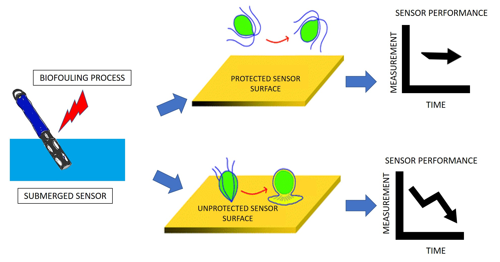
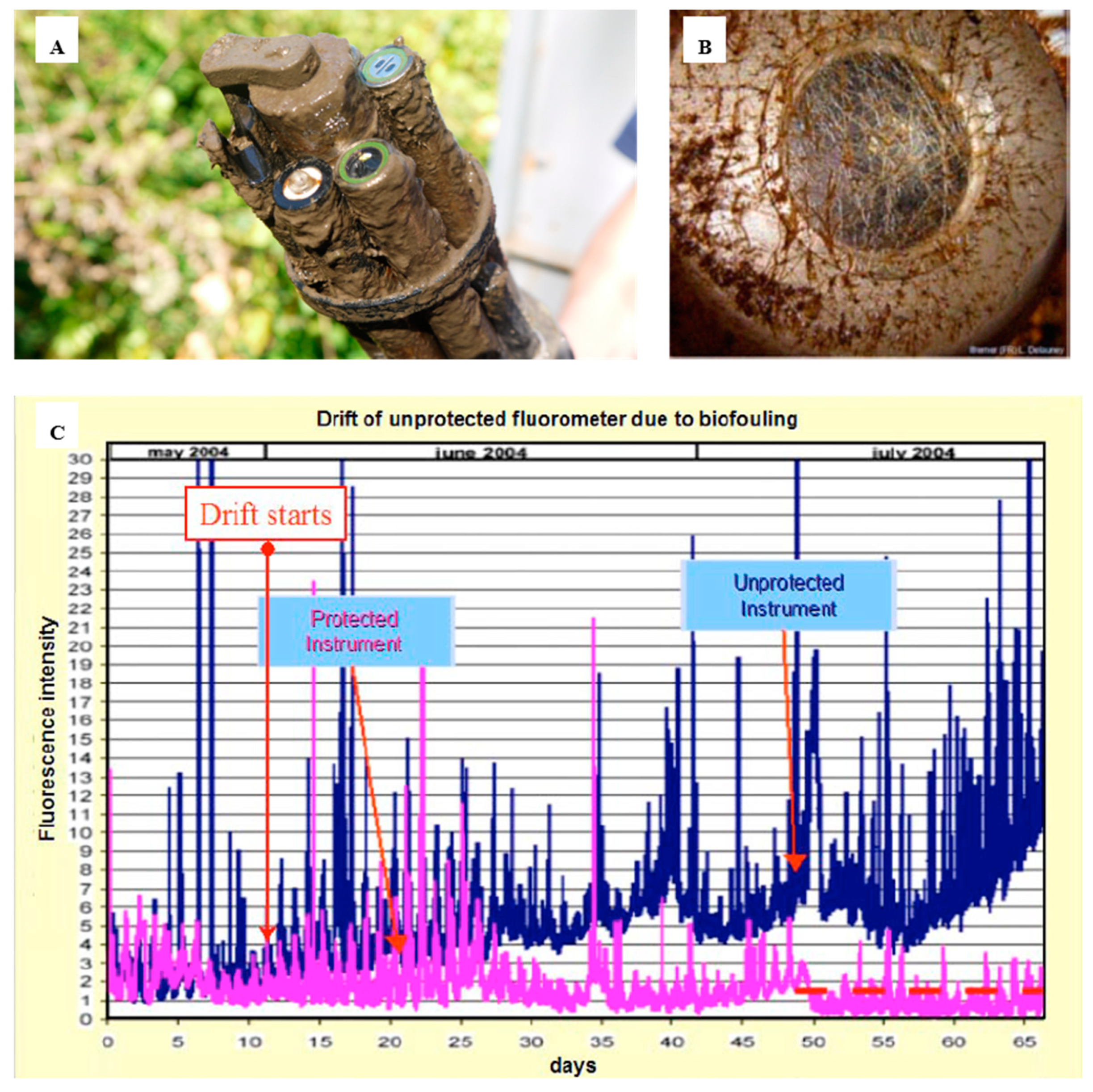
2. Fouling Overview
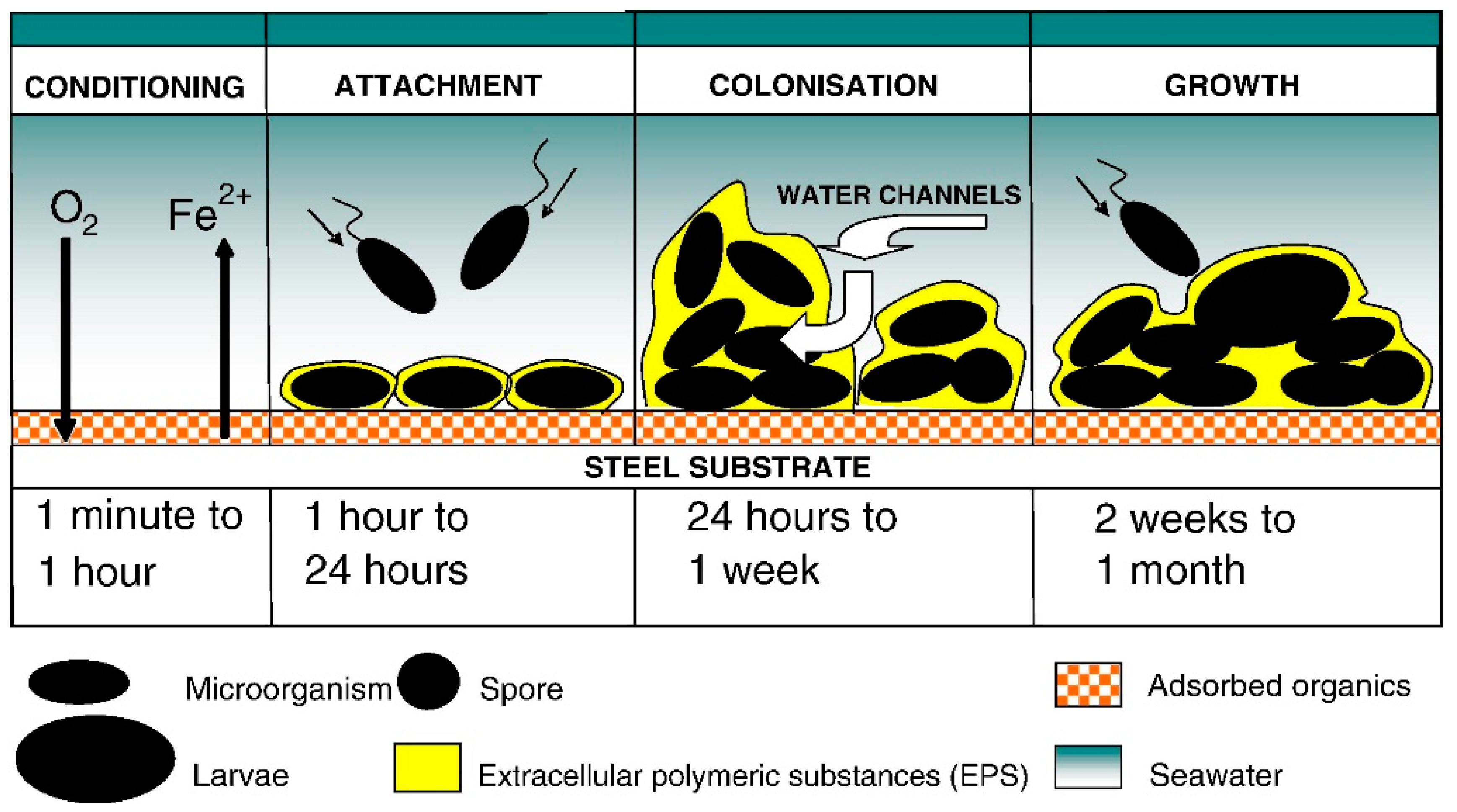
2.1. Mechanism of Biofilm Formation/Progression
2.2. Properties of Biofilms
3. Sensor Materials
4. Antifouling Strategies for Sensors
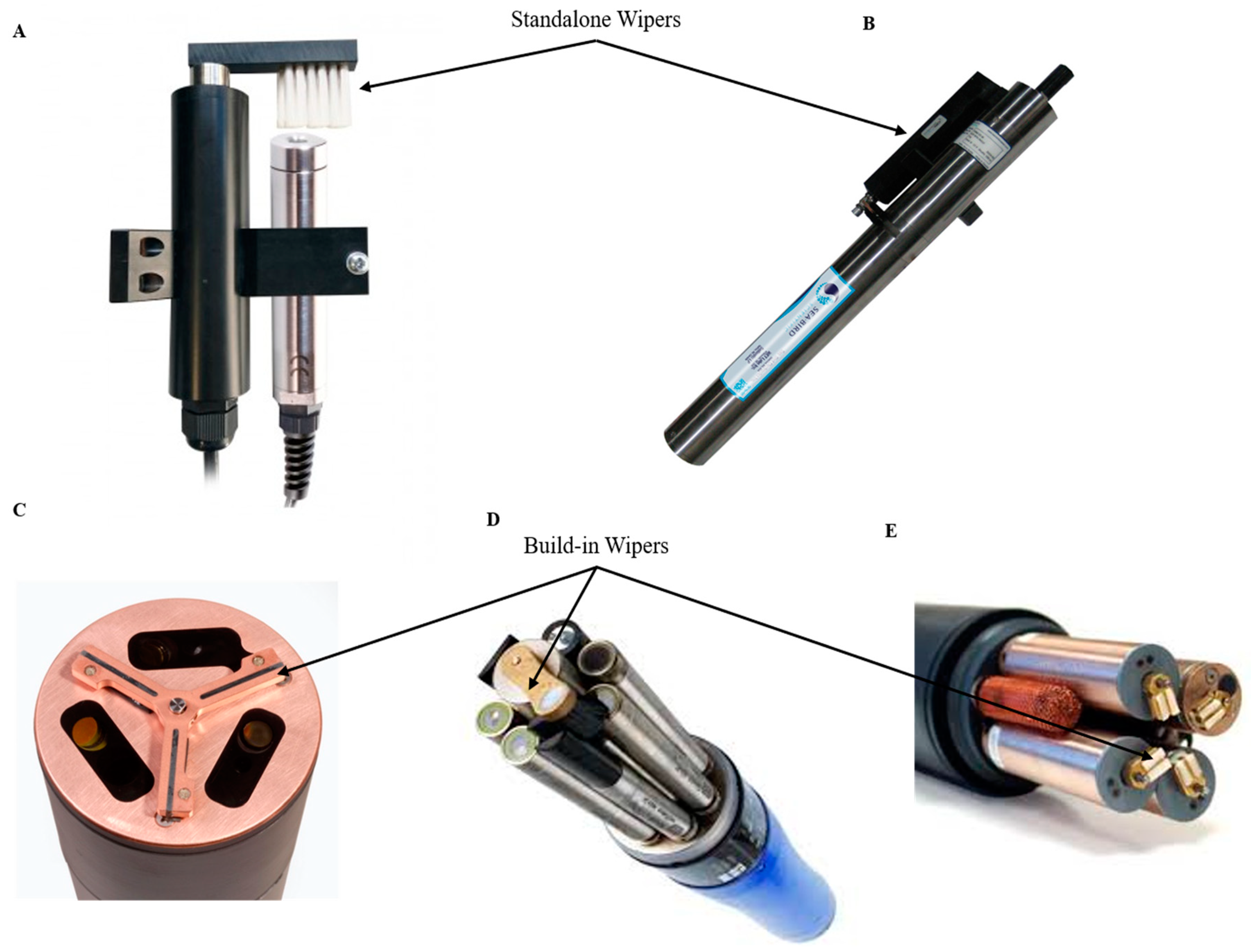
4.1. Wiper Technologies
4.2. Biocide Generation Systems
4.3. Antifouling Coatings
4.3.1. Non-Stick Coatings
4.3.2. Biocide Coatings
- Contact Leaching Coatings use high molecular weight binders that are insoluble in seawater, such as vinyl, acrylic and chlorinated rubber polymers. They have a high mechanical resistance and can incorporate high quantities of toxic particles. The mechanism of release of these particles is gradual because the binder matrix is not soluble in seawater and the toxic agents contained in this matrix are released, leaving small pores through which seawater penetrates. Over time, the toxic particles remain in the deeper layers of the matrix in which they are immersed, making access to seawater difficult. This gradually decreases the rate of release of the toxic particles, causing the degree of protection to decline. The duration of the efficiency for this type of coatings is between 12 and 24 months providing potential for sensor use [91].
- Controlled Depletion Polymer is known as soluble ablative or eroding paints. These coatings, unlike the previous ones, contain biocides that are mixed with a nontoxic soluble matrix based on high amounts of rosin and its derivatives. In contact with seawater, the binder containing the biocide dissolves, gradually releasing the biocide. The limit of protection against biofouling is 12–15 months because the erosion rate of the matrix containing the biocide is too high from the moment the surface is laid out in the water [91]. However, the use of controlled depletion polymer (CDP) coatings can be reinforced with synthetic resins that are much stronger and more durable than rosin derivatives. The main difference with CDP coatings is that the process of release of the biocide occurs by hydration and dissolution not by hydrolysis [90].
- Self-Polishing Copolymer Coatings (SPC) are based on the use of acrylics or methacrylics that are easily hydrolysable in seawater. These copolymers mixed with biocides give smooth surfaces and are able to promote the leaching by controlling the erosion rate of the matrix [92]. These methacrylic copolymers function similarly to the methacrylic organotinic copolymers used in TBT-based paints but using copper, zinc or silicon ester groups instead. The mechanism of release of the biocidal particles has been extensively studied by Hellio and Yebra. Sea water diffuses into the insoluble matrix, causing the dissolution of the ester groups releasing the biocide particles due to their hydrolytic instability under alkaline conditions, such as those found in sea water [93].
4.4. Electrochemical Antifouling Methods
4.5. Irradiation to Combat Biofouling
4.5.1. UV Radiation
4.5.2. Photocatalytic Materials
4.5.3. Laser Irradiation
4.5.4. Ultrasonic Irradiation
4.5.5. Biomimetic Antifouling Strategies
4.5.6. Fouling Management on Sensors
4.5.7. Summary of the Current State of the Art
4.5.8. Current Limitations and Future Directions
5. Conclusions
Author Contributions
Funding
Informed Consent Statement
Conflicts of Interest
References
- Characklis, W.G. Bioengineering report: Fouling biofilm development: A process analysis. Biotechnol. Bioeng. 1981, 23, 1923–1960. [Google Scholar] [CrossRef]
- Railkin, A.I. Marine Biofouling: Colonization Processes and Defenses; CRC Press: Boca Raton, FL, USA, 2003. [Google Scholar]
- Dafforn, K.A.; Lewis, J.A.; Johnston, E.L. Antifouling strategies: History and regulation, ecological impacts and mitigation. Mar. Pollut. Bull. 2011, 62, 453–465. [Google Scholar] [CrossRef] [PubMed]
- Davidson, I.C.; Brown, C.W.; Sytsma, M.D.; Ruiz, G.M. The role of containerships as transfer mechanisms of marine biofouling species. Biofouling 2009, 25, 645–655. [Google Scholar] [CrossRef]
- Champ, M.A. Economic and environmental impacts on ports and harbors from the convention to ban harmful marine anti-fouling systems. Mar. Pollut. Bull. 2003, 46, 935–940. [Google Scholar] [CrossRef]
- Swain, G. Biofouling control: A critical component of drag reduction. In Proceedings of the International Symposium on Sea Water Drag Reduction, Newport, RI, USA, 22–23 July 1998; pp. 155–161. [Google Scholar]
- Turner, A.; Singh, N.; Richards, J.P. Bioaccessibility of metals in soils and dusts contaminated by marine antifouling paint particles. Environ. Pollut. 2009, 157, 1526–1532. [Google Scholar] [CrossRef] [PubMed]
- Manov, D.V.; Chang, G.C.; Dickey, T.D. Methods for Reducing Biofouling of Moored Optical Sensors. J. Atmos. Ocean. Technol. 2004, 21, 958–968. [Google Scholar] [CrossRef]
- Whelan, A.; Regan, F. Antifouling strategies for marine and riverine sensors. J. Environ. Monit. 2006, 8, 880–886. [Google Scholar] [CrossRef]
- Whitt, C.; Pearlman, J.; Polagye, B.; Caimi, F.; Muller-Karger, F.; Copping, A.; Spence, H.; Madhusudhana, S.; Kirkwood, W.; Grosjean, L.; et al. Future Vision for Autonomous Ocean Observations. Front. Mar. Sci. 2020, 7, 697. [Google Scholar] [CrossRef]
- Delauney, L.; Compère, C.; Lehaitre, M.; Compare, C. Biofouling protection for marine environmental sensors. Ocean Sci. 2010, 6, 503–511. [Google Scholar] [CrossRef]
- Alliance for Coastal Technologies. Biofouling Prevention Technologies for Coastal Sensors/Sensor Platforms. In Proceedings of the University of Maryland Center of Environmental Science, Workshop Proceedings, Solomons, MD, USA, 19–21 November 2003; p. 23. [Google Scholar]
- Lobe, H. Recent advances in biofouling protection for oceanographic instrumentation. In Proceedings of the OCEANS 2015—MTS/IEEE Washington, Washington, DC, USA, 19–22 October 2015. [Google Scholar] [CrossRef]
- Little, B.J.; Wagner, P.A. Succession in Microfouling; CRC Press: Boca Raton, FL, USA, 1997. [Google Scholar]
- Afroz, F.; Lang, A.; Habegger, M.L. Bristled shark skin: A microgeometry for boundary layer control? Related content Experimental study of laminar and turbulent boundary layer separation control of shark skin. Bioinspir. Biomim. 2008, 3. [Google Scholar] [CrossRef]
- Zobell, C.E.; Allen, E.C. The significance of marine bacteria in the fouling of submerged surfaces. J. Bacteriol. 1935, 29, 239–251. [Google Scholar] [CrossRef] [PubMed]
- Zobell, C.E.; Rittenberg, S.C. The occurrence and characteristics of chitinoclastic bacteria in the sea. J. Bacteriol. 1938, 35, 275–287. [Google Scholar] [CrossRef] [PubMed]
- Busscher, H.J.; Bos, R.; Van Der Mei, H.C. Initial Microbial Adhesion is a Determinant for the Strength of Biofilm Adhesion. FEMS Microbiol. Lett. 1995, 128, 229–234. [Google Scholar] [CrossRef] [PubMed]
- Jain, A.; Bhosle, N.B. Biochemical composition of the marine conditioning film: Implications for bacterial adhesion. Biofouling 2009, 25, 13–19. [Google Scholar] [CrossRef] [PubMed]
- Roberts, D.; Rittschof, D.; Holm, E.; Schmidt, A. Factors influencing initial larval settlement: Temporal, spatial and surface molecular components. J. Exp. Mar. Bio. Ecol. 1991, 150, 203–221. [Google Scholar] [CrossRef]
- Chambers, L.D.; Stokes, K.R.; Walsh, F.C.; Wood, R.J.K. Modern approaches to marine antifouling coatings. Surf. Coatings Technol. 2006, 201, 3642–3652. [Google Scholar] [CrossRef]
- Nazar, C.J. Biofilms bacterianos. Rev. Otorrinolaringol. y Cirugía Cabeza y Cuello 2007, 67, 61–72. [Google Scholar] [CrossRef]
- Donlan, R.M. Biofilms: Microbial life on surfaces. Emerg. Infect. Dis. 2002, 8, 881–890. [Google Scholar] [CrossRef]
- Chloe, R.A.; Faddis, B.T. Anatomical evidence of microbial biofilms in tonsillar tissues: A possible mechanism to explain chronicity. Arch. Otolaryngol. Neck Surg. 2002, 129, 634–636. [Google Scholar]
- Post, J.C.; Stoodley, P.; Hall–Stoodley, L.; Ehrlich, G.D. The role of biofilms in otolaryngologic infections. Curr. Opin. Otolaryngol. Head Neck Surg. 2004, 12, 185–190. [Google Scholar] [CrossRef]
- Delrin® Plastic|Acetal Plastic. Available online: https://www.dupont.com/products/delrin.html (accessed on 31 December 2020).
- Solvay’s Ryton® PPS Used for Flexible, Lightweight Coolant Lines, Brackets and Connectors Advances Complex Automotive Thermal Management Assembly Systems|Solvay. Available online: https://www.solvay.com/en/article/solvays-ryton-pps-used-flexible-lightweight-coolant-lines-brackets-and-connectors-advances (accessed on 31 December 2020).
- Agarwal, D.C. A New Ni-Cr-Mo Alloy 59, UNS N06059, for Providing Cost-Effective/Reliable Solutions to Various Maintenance and Corrosion Problems in Naval Applications; ThyssenKrupp VDM USA, Inc.: Houston, TX, USA, 2007. [Google Scholar]
- Shin, Y.h.; Chung, J.h.; Kim, J.H. Test and estimation of ballistic armor performance for recent naval ship structural materials. Int. J. Nav. Archit. Ocean Eng. 2018, 10, 762–781. [Google Scholar] [CrossRef]
- Choung, J.; Nam, W.; Lee, J.Y. Dynamic hardening behaviors of various marine structural steels considering dependencies on strain rate and temperature. Mar. Struct. 2013, 32, 49–67. [Google Scholar] [CrossRef]
- Ailor, W.H. Five-year corrosion of aluminium alloys at several marine sites. Br. Corros. J. 1966, 1, 237–243. [Google Scholar] [CrossRef]
- Lopez, G.; Tiznado, H.; Soto Herrera, G.; De la Cruz, W.; Valdez, B.; Schorr, M.; Roumen, Z. Use of AES in corrosion of copper connectors of electronic devices and equipments in arid and marine environments. Anti-Corros. Methods Mater. 2011, 58, 331–336. [Google Scholar] [CrossRef]
- Lynch, R.F. Hot-Dip Galvanizing Alloys. JOM 1987, 39, 39–41. [Google Scholar] [CrossRef]
- Xu, C.; Zhang, Y.; Cheng, G.; Zhu, W. Localized corrosion behavior of 316L stainless steel in the presence of sulfate-reducing and iron-oxidizing bacteria. Mater. Sci. Eng. A 2007, 443, 235–241. [Google Scholar] [CrossRef]
- C3 Submersible Fluorometer; Turner Designs; United States. Available online: https://www.turnerdesigns.com/c3-submersible-fluorometer (accessed on 8 October 2020).
- C6P Submersible Fluorometer; Turner Designs; United States. Available online: https://www.turnerdesigns.com/c6p-submersible-fluorometer (accessed on 8 October 2020).
- Modular Underwater Pressure Housings. Available online: http://www.develogic.de/products/underwater-housing-systems/ (accessed on 8 October 2020).
- Lizotte, M. Fighting Fouling; Extending Sonde Deployment Times with EXO’s Wiped (C/T) Sensor; US Department of the Interior, US Geological Survey: Yellow Springs, OH, USA, 2015.
- VIPER-TriOS Mess-und Datentechnik. Available online: https://www.trios.de/en/viper.html (accessed on 5 October 2020).
- enviroFlu-TriOS Mess-und Datentechnik. Available online: https://www.trios.de/en/enviroflu.html (accessed on 5 October 2020).
- nanoFlu-TriOS Mess- und Datentechnik. Available online: https://www.trios.de/en/nanoflu.html (accessed on 5 October 2020).
- WQM Water Quality Monitor|Sea-Bird Scientific-Videos|Sea-Bird. Available online: https://www.seabird.com/moored/wqm-water-quality-monitor/family-video?productCategoryId=54627473783 (accessed on 5 October 2020).
- ECO Scattering Sensor, Sea-Bird Scientific. Available online: https://www.seabird.com/scattering-sensors/eco-scattering-sensor/family?productCategoryId=54627869916 (accessed on 5 October 2020).
- ECO Triplet, Sea-Bird Scientific. Available online: https://www.seabird.com/combination-sensors/eco-triplet/family?productCategoryId=54758054351# (accessed on 5 October 2020).
- HydroCAT-EP, Sea Bird Scientific, User Manual. Available online: https://www.google.com/search?rlz=1C1CHBF_esES913ES913&sxsrf=ALeKk03IIi6AodF6GvbgCEOD6lA5skPWbA%3A1601933486724&ei=rpB7X7bWK6Wd1fAPvqKfoAk&q=HydroCAT-EP+user+manual&oq=HydroCAT-EP+user+manual&gs_lcp=CgZwc3ktYWIQAzoFCAAQywE6BAgAEB46BQghEKABOgcIIRAKEKABSgUI (accessed on 5 October 2020).
- HyperOCR Radiometer, Sea-Bird Scientific. Available online: https://www.seabird.com/hyperspectral-radiometers/hyperocr-radiometer/family?productCategoryId=54627869935 (accessed on 6 October 2020).
- ECO Photosynthetically Active Radiation (PAR) Sensor, Sea-Bird Scientific. Available online: https://www.seabird.com/multispectral-radiometers/eco-photosynthetically-active-radiation-par-sensor/family?productCategoryId=54627869940 (accessed on 6 October 2020).
- Multispectral Radiometers, Sea-Bird Scientific. Available online: https://www.seabird.com/multispectral-radiometers/multispectral-radiometers/family?productCategoryId=54627869938 (accessed on 6 October 2020).
- WQM Water Quality Monitor Sea-Bird Scientific. Available online: https://www.seabird.com/moored/wqm-water-quality-monitor/family?productCategoryId=54627473783 (accessed on 5 October 2020).
- Water Quality Monitor (WQM) Sea Bird Scientific, User Manual 12/2013, Edition 1. Available online: https://www.ott.com/download/sea-bird-scientific-wqm-manual/ (accessed on 5 October 2020).
- Multiparameter Sondes for Water Quality Monitoring Data Collection; © 2020 YSI, a Xylem Brand. Available online: https://www.ysi.com/products/multiparameter-sondes (accessed on 6 October 2020).
- 6-Series Anti-Fouling Kits System Inhibits Biofouling to Lengthen Deployment Times and Reduce Operating Costs; © 2020 YSI, a Xylem Brand. Available online: https://www.fondriest.com/pdf/ysi_af_spec.pdf (accessed on 6 October 2020).
- UV254 Products. Available online: https://www.photonicmeasurements.com/products (accessed on 6 October 2020).
- Sonde DCO UV-Probe 254+ Multi-Paramètres-EFS. Available online: https://www.efs.fr/project/sonde-dco-uv-probe-254/ (accessed on 6 October 2020).
- VLux AlgaePro-Chelsea Technologies. Available online: https://chelsea.co.uk/products/vlux-algaepro/ (accessed on 8 October 2020).
- Hydro-Wiper; Zebra Tech. Available online: https://www.zebra-tech.co.nz/hydro-wiper/ (accessed on 9 October 2020).
- OBS501 Smart Turbidity Meter with Antifouling Features; CampBell-Scientific. Available online: https://www.campbellsci.eu/turbidity (accessed on 7 October 2020).
- Hydrolab DS5X-Multiparameter Data Sonde-OTT Hydromet. Available online: https://www.ott.com/products/water-quality-2/hydrolab-ds5x-multiparameter-data-sonde-855/ (accessed on 6 November 2020).
- Spectrometer Probes; S::can. Available online: https://www.s-can.at/index.php?option=com_virtuemart&view=category&virtuemart_category_id=1&virtuemart_manufacturer_id=0&categorylayout=0&showcategory=1&showproducts=1&productsublayout=0&Itemid=731&scrollto=product-145 (accessed on 9 October 2020).
- Granhag, L.M.; Finlay, J.A.; Jonsson, P.R.; Callow, J.A.; Callow, M.E. Roughness-dependent removal of settled spores of the green alga Ulva (syn. Enteromorpha) exposed to hydrodynamic forces from a water jet. Biofouling 2004, 20, 117–122. [Google Scholar] [CrossRef]
- Multiparameter Water Quality Instrument; YSI EXO 2 Sonde, © 2020 YSI, a Xylem Brand. Available online: https://www.ysi.com/EXO2 (accessed on 6 October 2020).
- Ponsel Hydroclean_P Anti Fouling Wiper. Available online: https://www.bellenviro.co.uk/ponsel-hydroclean_p-anti-fouling-wiper.html (accessed on 5 October 2020).
- SUNA V2 Nitrate Sensor|Sea-Bird Scientific-Overview|Sea-Bird. Available online: https://www.seabird.com/nutrient-sensors/suna-v2-nitrate-sensor/family?productCategoryId=54627869922 (accessed on 5 October 2020).
- ECO Triplet-w Sea-Bird Scientific. Available online: https://www.seabird.com/combination-sensors/eco-triplet-w/family?productCategoryId=54627869918 (accessed on 5 October 2020).
- YSI Inc. 6-Series Anti-Fouling Kits System Inhibits Biofouling to Lengthen Deployment Times and Reduce Operating Costs; YSI Inc.: Yellow Springs, OH, USA, 2010. [Google Scholar]
- Sreenivasan, P.K.; Chorny, R.C. The effects of disinfectant foam on microbial biofilms. Biofouling 2005, 21, 141–149. [Google Scholar] [CrossRef]
- Davis, R.F.; Moore, C.C.; Zaneveld, J.R.V.; Napp, J.M. Reducing the effects of fouling on chlorophyll estimates derived from long-term deployments of optical instruments. J. Geophys. Res. Oceans 1997, 102, 5851–5855. [Google Scholar] [CrossRef]
- Rajagopal, S.; Van Der Velde, G.; Van Der Gaag, M.; Jenner, H.A. Laboratory evaluation of the toxicity of chlorine to the fouling hydroid Cordylophora caspia. Biofouling 2002, 18, 57–64. [Google Scholar] [CrossRef]
- McGinnis, C.L.; Crivello, J.F. Elucidating the mechanism of action of tributyltin (TBT) in zebrafish. Aquat. Toxicol. 2011, 103, 25–31. [Google Scholar] [CrossRef] [PubMed]
- Alzieu, C. Tributyltin: Case study of a chronic contaminant in the coastal environment. Ocean Coast. Manag. 1998, 40, 23–36. [Google Scholar] [CrossRef]
- Stauber, J.L.; Florence, T.M. Mechanism of toxicity of ionic copper and copper complexes to algae. Mar. Biol. 1987, 94, 511–519. [Google Scholar] [CrossRef]
- Breur, H. Fouling and Bioprotection of Metals: Monitoring and Control of Deposition Processes in Aqueous Environments. Available online: http://resolver.tudelft.nl/uuid:d5455703-294c-4187-86e2-b5b4de636b4e (accessed on 31 December 2020).
- Soldo, D.; Hari, R.; Sigg, L.; Behra, R. Tolerance of Oocystis nephrocytioides to copper: Intracellular distribution and extracellular complexation of copper. Aquat. Toxicol. 2005, 71, 307–317. [Google Scholar] [CrossRef] [PubMed]
- Mudryk, Z.J. Antibiotic Resistance among Bacteria Inhabiting Surface and Subsurface Water Layers in Estuarine Lake Gardno. Pol. J. Environ. Stud. 2002, 11, 401–406. [Google Scholar]
- Kobori, H.; Sullivan, C.W.; Shizuya, H. Bacterial Plasmids in Antarctic Natural Microbial Assemblages. Appl. Environ. Microbiol. 1984, 48, 515–518. [Google Scholar] [CrossRef]
- Gerigk, U.; Schneider, U.; Stewen, U. The present status of TBT copolymer antifouling paints versus TBT-free technology. In Proceedings of the 216th ACS Annual Meeting, Boston, MA, USA, 23–27 August 1998; pp. 91–94. [Google Scholar]
- Omae, I. Organotin antifouling paints and their alternatives. Appl. Organomet. Chem. 2003, 17, 81–105. [Google Scholar] [CrossRef]
- Voulvoulis, N.; Scrimshaw, M.D.; Lester, J.N. Alternative antifouling biocides. Appl. Organomet. Chem. 1999, 13, 135–143. [Google Scholar] [CrossRef]
- Thomas, K.V. The environmental fate and behaviour of antifouling paint booster biocides: A review. Biofouling 2001, 17, 73–86. [Google Scholar] [CrossRef]
- Bringhurst, B.T.; Christensen, C.B.; Ewert, D.W.; Thurston, R.J.; John, P.; Downing, J. Sensor with Antifouling Control. U.S. Patent No. 8,429,952, 30 April 2013. [Google Scholar]
- Cook, M. Using a Copper-Alloy Based System for Effective Biofouling Deterrence New Anti-Fouling Methods from YSI Inc. Reduce Impact of Biological Fouling on Water Monitoring Instrumentation; YSI Inc.: Yellow Springs, OH, USA, 2010. [Google Scholar]
- Higgins, P. Tips to Prevent Biofouling on Water Quality Instruments Recommended Anti-Fouling Items: Anti-Fouling Wipers, Anti-fouling Port Plugs 2" Wide Copper Tape, Plastic Anti-Fouling Sleeves, Copper-Alloy Sensor Guard, Copper-Alloy Screen, C-Spray Protective Prob; YSI Inc.: Yellow Springs, OH, USA, 2013. [Google Scholar]
- Kerr, A.; Cowling, M.J.; Beveridge, C.M.; Smith, M.J.; Parr, A.C.S.; Head, R.M.; Davenport, J.; Hodgkiess, T. The early stages of marine biofouling and its effect on two types of optical sensors. Environ. Int. 1998, 24, 331–343. [Google Scholar] [CrossRef]
- Lindner, E. A low surface free energy approach in the control of marine biofouling. Biofouling 1992, 6, 193–205. [Google Scholar] [CrossRef]
- Tang, Y.; Finlay, J.A.; Kowalke, G.L.; Meyer, A.E.; Bright, F.V.; Callow, M.E.; Callow, J.A.; Wendt, D.E.; Detty, M.R. Hybrid xerogel films as novel coatings for antifouling and fouling release. Biofouling 2005, 21, 59–71. [Google Scholar] [CrossRef] [PubMed]
- Dugdale, T.M.; Wetherbee, R.; Brennan, A. Adhesion and motility of fouling diatoms on a silicone elastomer The effectiveness of invasive species management in wetlands View project 15th International Symposium on Aquatic Plants View project. Taylor Fr. 2004, 20, 323–329. [Google Scholar] [CrossRef]
- Tao, S.; Xu, L.; Fanguy, J.C. Optical fiber ammonia sensing probes using reagent immobilized porous silica coating as transducers. Sens. Actuators B Chem. 2006, 115, 158–163. [Google Scholar] [CrossRef]
- Hu, Z.; Pitet, L.M.; Hillmyer, M.A.; Desimone, J.M. High Modulus, Low Surface Energy, Photochemically Cured Materials from Liquid Precursors. Macromolecules 2010, 43, 10397–10405. [Google Scholar] [CrossRef]
- Lewis, A. Phosphorylcholine-based polymers and their use in the prevention of biofouling. Colloids Surf. B Biointerfaces 2000, 18, 261–275. [Google Scholar] [CrossRef]
- Lejars, M.; Margaillan, A.; Bressy, C. Fouling release coatings: A nontoxic alternative to biocidal antifouling coatings. Chem. Rev. 2012, 112, 4347–4390. [Google Scholar]
- Almeida, E.; Diamantino, T.C.; de Sousa, O. Marine paints: The particular case of antifouling paints. Prog. Org. Coat. 2007, 59, 2–20. [Google Scholar] [CrossRef]
- Omae, I. General aspects of tin-free antifouling paints. Chem. Rev. 2003, 103, 3431–3448. [Google Scholar] [CrossRef]
- Hellio, C.; Yebra, D. Advances in Marine Antifouling Coatings and Technologies; Hellio, C., Yebra, D., Eds.; Woodshead Publishing: Cambridge, UK, 2009. [Google Scholar]
- Wood, P.; Jones, M.; Bhakoo, M.; Gilbert, P. A Novel Strategy for Control of Microbial Biofilms through Generation of Biocide at the Biofilm-Surface Interface. Appl. Environ. Microbiol. 1996, 62, 2598–2602. [Google Scholar] [CrossRef]
- Nakasono, S.; Matsunaga, T. Electrochemical Sterilization of Marine Bacteria Adsorbed onto a Graphite-Silicone Electrode by Application of an Alternating Potential. Denki Kagaku oyobi Kogyo Butsuri Kagaku 1993, 61, 899–902. [Google Scholar] [CrossRef]
- Nakayama, T.; Wake, H.; Ozawa, K.; Kodama, H.; Nakamura, N.; Matsunaga, T. Use of a titanium nitride for electrochemical inactivation of marine bacteria. Environ. Sci. Technol. 1998, 32, 798–801. [Google Scholar] [CrossRef]
- Amr, A.-G.K.H.S. Biofouling prevention with pulsed electric fields. IEEE Trans. Plasma Sci. 2000, 28, 115–121. [Google Scholar] [CrossRef]
- Laurent, D.; Kada, B.; Mathieu, D.; Bertrand, F.; Michel, P.; Giovanni, P.; Faimali, M. Optimized and High Efficiency Biofouling Protection for Oceanographic Optical Devices. In Proceedings of the OCEANS 2017—Aberdeen, Aberdeen, UK, 19–22 June 2017; pp. 1–14. [Google Scholar]
- Tribollet, B.; Cachet, H.; Festy, D. Method for Production of an Anti-Fouling Protective Coating on a Support and Corresponding Support. Patent WO 2004069645 A1, 19 August 2004. [Google Scholar]
- Debiemme-Chouvy, C.; Hua, Y.; Hui, F.; Duval, J.-L.; Cachet, H. Electrochemical treatments using tin oxide anode to prevent biofouling. Electrochim. Acta 2011, 56, 10364–10370. [Google Scholar] [CrossRef]
- Spears, L.G.; Stone, J.H.; Klein, E. Electrolysis of copper screening: A technique for the prevention of marine fouling. Environ. Sci. Technol. 1969, 3, 576–580. [Google Scholar] [CrossRef]
- Hindler, J.A.; Howard, B.J.; Keiser, J.F. Clinical and Pathogenic Microbiology; Mosby-Year Book Inc.: St. Louis, MO, USA, 1994; pp. 145–195. [Google Scholar]
- Boyce, J.M. Modern technologies for improving cleaning and disinfection of environmental surfaces in hospitals. Antimicrob. Resist. Infect. Control 2016, 5, 1–10. [Google Scholar] [CrossRef]
- Titus, J.M.; Ryskiewich, B.S. Ultraviolet Marine Anti-Biofouling Systems. U.S. Patent 5322569, 21 June 1994. [Google Scholar]
- Zheng, J.; Feng, C.; Matsuura, T. Study on reduction of inorganic membrane fouling by ultraviolet irradiation. J. Memb. Sci. 2004, 244, 179–182. [Google Scholar] [CrossRef]
- Blatchley, E.R.; Bastian, K.C.; Duggirala, R.K.; Alleman, J.E.; Moore, M.; Schuerch, P. Ultraviolet irradiation and chlorination/dechlorination for municipal wastewater disinfection: Assessment of performance limitations. Water Environ. Res. 1996, 68, 194–204. [Google Scholar] [CrossRef]
- Koutchma, T. UV Light for Processing Foods. Ozone Sci. Eng. 2008, 30, 93–98. [Google Scholar] [CrossRef]
- Jongerius, M.; Paulussen, E.; Visser, C.; Wijnen, M.; Hietbrink, R. UVC Antifouling Solutions Device Design Simulation and Experimental Verification. RunWell. Philips Royal. Available online: https://411.fit.edu/icmcf/documents/Michael%20Jongerius.pdf 2018 (accessed on 7 October 2020).
- Jehan, Z. Foul Free at Folger Pinnacle; AML Oceanographic. Available online: https://amloceanographic.com/case-studies/foul-free-folger-pinnacle/ (accessed on 7 October 2020).
- UV-LED Antifouling Lights; Mariscope Meerestechnik. Available online: http://www.mariscope.de/product/uv-led-antifouling/ (accessed on 9 October 2020).
- UV•Xchange-AML Oceanographic. Available online: https://amloceanographic.com/all-instrumentation/uv-xchange/ (accessed on 7 October 2020).
- Linkous, C.A.; Carter, G.J.; Locuson, D.B.; Ouellette, A.J.; Slattery, D.K.; Smitha, L.A. Photocatalytic Inhibition of Algae Growth Using TiO2, WO3, and Cocatalyst Modifications. Environ. Sci. Technol. 2000, 34, 4754–4758. [Google Scholar] [CrossRef]
- Liu, K.; Jiang, L. Bio-Inspired Self-Cleaning Surfaces. Annu. Rev. Mater. Res. 2012, 42, 231–263. [Google Scholar] [CrossRef]
- Genzer, J.; Efimenko, K. Recent developments in superhydrophobic surfaces and their relevance to marine fouling: A review. Biofouling 2006, 22, 339–360. [Google Scholar] [CrossRef] [PubMed]
- Sun, R.-D.; Nakajima, A.; Fujishima, A.; Watanabe, T.; Hashimoto, K. Photoinduced Surface Wettability Conversion of ZnO and TiO2 Thin Films. J. Phys. Chem. B 2001, 105, 1984–1990. [Google Scholar] [CrossRef]
- Morris, R.S.; Myles, A. Walsh Zinc Oxide Photoactive Material. U.S. Patent 6063849, 29 June 1999. [Google Scholar]
- Liu, H.; Feng, L.; Zhai, J.; Jiang, L.; Zhu, D. Reversible Wettability of a Chemical Vapor Deposition Prepared ZnO Film between Superhydrophobicity and Superhydrophilicity. Langmuir 2004, 20, 5659–5661. [Google Scholar] [CrossRef]
- Wu, X.; Zheng, L.; Wu, D. Fabrication of Superhydrophobic Surfaces from Microstructured ZnO-Based Surfaces via a Wet-Chemical Route. Langmuir 2005, 21, 2665–2667. [Google Scholar] [CrossRef]
- Nandakumar, K.; Obika, H.; Shinozaki, T.; Ooie, T.; Utsumi, A.; Yano, T. Pulsed laser irradiation impact on two marine diatoms Skeletonema costatum and Chaetoceros gracilis. Water Res. 2003, 37, 2311–2316. [Google Scholar] [CrossRef]
- Nandakumar, K.; Obika, H.; Shinozaki, T.; Ooie, T.; Utsumi, A.; Yano, T. Lethal and sub-lethal impacts of pulsed laser irradiations on the larvae of the fouling barnacle Balanus amphitrite. Biofouling 2003, 19, 169–176. [Google Scholar] [CrossRef]
- Kitamura, H.; Takahashi, K.; Kanamaru, D. Inhibitory Effect of Ultrasonic Waves on the Larval Settlement of the Barnacle, Balanus amphitrite in the Laboratory. Mar. Fouling 1995, 12, 9–13. [Google Scholar] [CrossRef]
- Mazue, G.; Viennet, R.; Hihn, J.-Y.; Carpentier, L.; Devidal, P.; Albaïna, I. Large-scale ultrasonic cleaning system: Design of a multi-transducer device for boat cleaning (20 kHz). Ultrason. Sonochem. 2011, 18, 895–900. [Google Scholar] [CrossRef]
- Guo, S.F.; Lee, H.P.; Chaw, K.C.; Miklas, J.; Teo, S.L.; Dickinson, G.H.; Birch, W.R.; Khoo, B.C. Effect of ultrasound on cyprids and juvenile barnacles. Biofouling 2011, 27, 185–192. [Google Scholar] [CrossRef]
- Guo, S.; Lee, P.H.; Khoo, B.C. Inhibitory effect of ultrasound on barnacle (Amphibalanus amphitrite) cyprid settlement. J. Exp. Mar. Biol. Ecol. 2011, 409, 253–258. [Google Scholar] [CrossRef]
- Choi, C.H.; Scardino, A.J.; Dylejko, P.G.; Fletcher, L.E.; Juniper, R. The effect of vibration frequency and amplitude on biofouling deterrence. Biofouling 2013, 29, 195–202. [Google Scholar] [CrossRef] [PubMed]
- Edgerton, G.A. Oceanographic Sensor with In-Situ Cleaning and Bio-Fouling Prevention System. US4092858A, 6 June 1978. [Google Scholar]
- Donskoy, D.M.; Bruno, M.S. The Use of Acoustic, Vibrational, and Hydrodynamic Techniques to Control Zebra Mussel Infestation; New Jersey Environmental Digital Library: Hoboken, NJ, USA, 1996. [Google Scholar]
- Scardino, A.J.; de Nys, R. Mini review: Biomimetic models and bioinspired surfaces for fouling control. Biofouling 2011, 27, 73–86. [Google Scholar] [CrossRef] [PubMed]
- Bhushan, B. Biomimetics: Lessons from nature—An overview. Philos. Trans. R. Soc. A Math. Phys. Eng. Sci. 2009, 367, 1445–1486. [Google Scholar] [CrossRef] [PubMed]
- Salta, M.; Wharton, J.A.; Stoodley, P.; Dennington, S.P.; Goodes, L.R.; Werwinski, S.; Mart, U.; Wood, R.J.K.; Stokes, K.R. Designing biomimetic antifouling surfaces. Trans. R. Soc. A 2010, 368, 4729–4754. [Google Scholar] [CrossRef] [PubMed]
- Delauney, L.; Cowie, P. Biofouling Resistant Infrastructure for Measuring, Observing and Monitoring. Available online: https://cordis.europa.eu/project/id/EVR1-CT-2002-40023 (accessed on 7 October 2020).
- FlowCell USC-TriOS Optical Sensors. Available online: https://www.trios.de/en/flowcell-usc.html (accessed on 9 October 2020).
- Albaladejo, C.; Sánchez, P.; Iborra, A.; Soto, F.; López, J.A.; Torres, R. Wireless sensor networks for oceanographic monitoring: A systematic review. Sensors 2010, 10, 6948. [Google Scholar] [CrossRef] [PubMed]
- Wilson, E. Understanding the Fundamental Optical Principles of UV-Based Antifouling. Bachelor’s Thesis, Lund University, Lund, Sweden, 2018. [Google Scholar]
- Grandison, C.; Piola, R.; Fletcher, L. A Review of Marine Growth Protection System (MGPS) Options for the Royal Australian Navy. Available online: https://apps.dtic.mil/dtic/tr/fulltext/u2/a557490.pdf (accessed on 7 October 2020).
- Willis, J.P. Biofouling Self-Compensating Biosensor. U.S. Patent No. WO2008079435A3, 23 October 2008. [Google Scholar]


| Material | Sample Use of Material in a Sensor | Sensor Type or Application |
|---|---|---|
| Metals | ||
| Titanium | Sensor housings | Available in commercial turbidity sensors |
| Anodised aluminium | Sensor housings | All, freshwater applications |
| 304L Stainless steel | Sensor housings | Specifically, marine applications and corrosive industrial applications |
| 316L Stainless steel | Filtration | Available for particulate matter screening on some conductivity ad temperature sensors |
| Stainless steel microscreens | Sensor housings | Replacement for SS housings |
| Copper | Antifouling | Most commercial systems |
| Plastics | ||
| Polyoxymethylene (Acetal, Delrin® (Wilmington, DE, USA)) [26] | Sensor housings | Available on commercial pH, fluorimetry and ORP sensors |
| Polyphenylene sulphide (PPS) (Ryton®) (Bollate, ITALY) [27] | Sensor housings | Some pH and ORP sensors |
| FEP Teflon | Membranes | Dissolved oxygen |
| Polyurethane | Cables | Most |
| Acrylonitrile butadiene styrene (ABS) | Sensor housings | Some models; OTT Orpheus Mini |
| HD polyurethane | Cables | Most |
| Poly Vinyl Chloride (PVC) | Cables | Most |
| Cross-Linked Polyethylene (XLPE) | Cables | Most |
| Chloroprene Rubber (CR) | Cables | Most |
| Polyurethane (PUR) | Cables | Most |
| Other Materials | ||
| Epoxy resins | Electronics, housing material | Most |
| Silicon | Diaphragms | Water level sensors |
| Sapphire | Optical windows | Turbidity |
| PVDF membranes | Filtration membranes | Phosphate, combined models |
| Glass | Optical windows | Turbidity |
| Fused Silica | Optical windows | Most |
| Manufacturer | Sensor Type | Model | Antifouling Strategy | Protected Component | Reference |
|---|---|---|---|---|---|
| TriOS | Photometer | TriOS VIPER | Coatings, ultrasonication cell | Optical window | [39] |
| Fluorometer | TriOS enviroFlu | Coatings | Optical window | [40] | |
| TriOS nanoFlu | Coatings | Optical window | [41] | ||
| Sea-Bird Scientific | Fluorometer | Sea-Bird Scientific ECO Fluorometer | Wiper + copper plate | Optical head and optical windows | [42] |
| Scattering | Sea-Bird Scientific ECO Scattering Sensor | Wiper + copper plate | Optical head and optical windows | [43] | |
| Combined scattering and fluorescence | Sea-Bird Scientific ECO Triplet | Wiper + copper plate | Optical head and optical windows | [44] | |
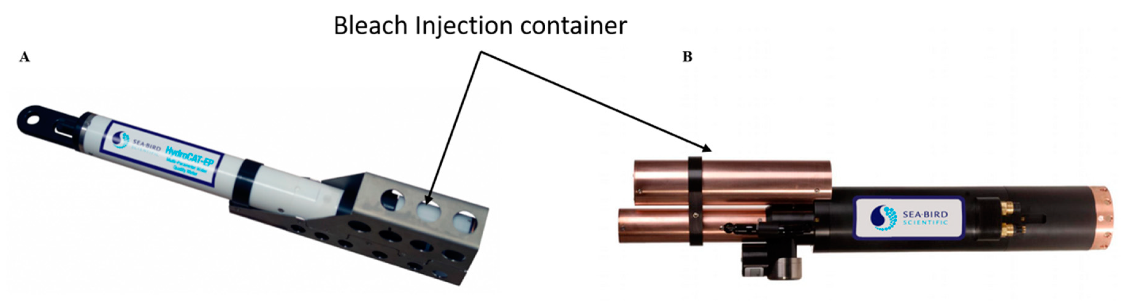
| Multi-parameter: CTD, ODO, pH | Sea-Bird HydroCAT-EP | Active flow control, passive flow prevention, light-blocking, active biocide (TBTO) injection, passive inhibitors and copper faceplate and wiper | Optical head. optical windows, sensor housing, conductivity cell and temperature probe | [45] | |
| Hyperspectral Radiometer | Sea-Bird Scientific HyperOCR Radiometer | Copper shutter | Optical window | [46] | |
| Multispectral Radiometer | Sea-Bird Scientific ECO PAR | Wiper + shutter Copper plate | Optical head and optical windows | [47] | |
| Sea-Bird Scientific OCR | Copper shutter | Optical windows | [48] | ||
| Sea-Bird and Wet-Labs | Combined fluorometer-turbidity and CTD | Wet-Labs and Sea-Bird Scientific WQM | Active flow control, passive flow prevention, light-blocking, active biocide (TBTO) injection and passive inhibitors | Optical head. optical windows and sensor housing | [49,50] |
| YSI, a Xylem brand | Multiparameter-modules | YSI EXO-series | Central Wiper, copper guard, copper sleeves/mesh, antifouling sleeves for overall sensor body, antifouling spray | Optical head, optical windows and sensor housing | [51] |
| YSI 6 series | Probe wiper, copper sleeves, copper alloys | Optical head and optical windows | [52] | ||
| Photonic Measurements | Spectrometer | UV254 Probe | Pressurised water cleaning | Optical window | [53] |
| EFS | Multiparameter UV-probe | COD UV-Probe 254+ | Compressed air-module | Optical window | [54] |
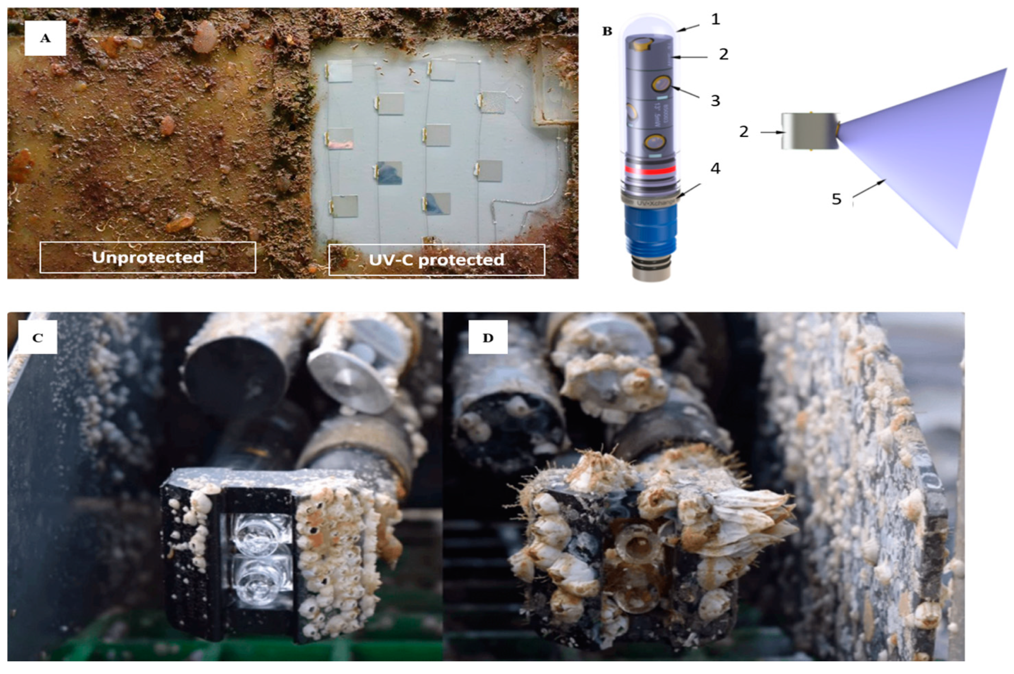
| Chelsea Technologies | Fluorometer | VLux Algae Pro | UV light, copper bezels and Hydro-Wiper | Optical window | [55,56] |
| Campbell Scientific | Turbidity meter | OBS501 | Shutter/wiper mechanism + biocide chamber + copper alloys | Optical window | [57] |
| Turner Designs | Fluorometer | C3 | Copper tape + mechanical copper wiper | Optical window | [35] |
| Fluorometer | C6P | Copper tape + mechanical copper wiper | Optical window | [36] | |
| Hydrolabs | Multiparameter-modules | DS5X | Central Wiper, copper guard, copper mesh, copper tape | Optical head, optical windows, pH and temperature probes | [58] |
| S::can | Spectrometer | Spectro::lyser V3 | Compressed air or brush | Optical window | [59] |
Publisher’s Note: MDPI stays neutral with regard to jurisdictional claims in published maps and institutional affiliations. |
© 2021 by the authors. Licensee MDPI, Basel, Switzerland. This article is an open access article distributed under the terms and conditions of the Creative Commons Attribution (CC BY) license (http://creativecommons.org/licenses/by/4.0/).
Share and Cite
Delgado, A.; Briciu-Burghina, C.; Regan, F. Antifouling Strategies for Sensors Used in Water Monitoring: Review and Future Perspectives. Sensors 2021, 21, 389. https://doi.org/10.3390/s21020389
Delgado A, Briciu-Burghina C, Regan F. Antifouling Strategies for Sensors Used in Water Monitoring: Review and Future Perspectives. Sensors. 2021; 21(2):389. https://doi.org/10.3390/s21020389
Chicago/Turabian StyleDelgado, Adrián, Ciprian Briciu-Burghina, and Fiona Regan. 2021. "Antifouling Strategies for Sensors Used in Water Monitoring: Review and Future Perspectives" Sensors 21, no. 2: 389. https://doi.org/10.3390/s21020389
APA StyleDelgado, A., Briciu-Burghina, C., & Regan, F. (2021). Antifouling Strategies for Sensors Used in Water Monitoring: Review and Future Perspectives. Sensors, 21(2), 389. https://doi.org/10.3390/s21020389