1. Introduction
Since the 1980s, mobile service robot technology has gradually become one of the research hotspots of researchers at home and abroad, and its application scope has also gradually expanded to space exploration [
1], military reconnaissance, explosive disposal rescue [
2], entertainment services, and other fields [
3].
Nowadays, the ground mobile robots are the most widespread category of mobile device robots, and their application direction is far superior to that of industrial robots. For this research, a great amount of research has been done and a lot of effort has been made [
4]. Ground mobile robots include wheeled robot, legged robot, and tracked robot. Wheeled robots can move simply and effectively at high speed and stably on flat and complex roads or sloping terrain [
5], but in unstructured environments, the use of legged and tracked robots is also a valuable option. Tracked robots can move on rugged and uneven terrain, because their contact surface with the ground is much larger than wheeled and legged robots [
6], which can make the operation more stable, but they usually move more slowly and with lower energy efficiency.
Among so many mobile mechanisms, wheeled and tracked robots are the most studied, but legged robots have also been researched because of their good obstacle crossing ability, such as BigDog [
7]. However, because the leg structure is complex and highly integrated, its cost is also expensive, especially for the robot with dynamic gait planning, as the high complexity of its dynamic gait is related not only to control, but also to mechanical structure. Therefore, reducing the number of legs can simplify its complexity and reduce its cost [
8]. At present, most legged robots are bipedal, quadruped, and hexapod [
9]. However, due to the increasing requirements for application fields, for the common mobile robot it has been difficult to meet all requirements, so hybrid robots have been developed [
10].
At present, the hybrid robot mainly has wheel-legged hybrid robot (WLHR), wheel-tracked hybrid robot (WTHR), wheel-track-leg hybrid robot (WTLHR), and so on. The WLHR has both the rapidity and smoothness of the wheeled robot and the superior obstacle performance of the legged robot. It can adjust its movement posture according to the external environment and is widely used in space exploration and military investigation [
11]. According to the structure, it can be roughly categorized into wheel-leg connected type, wheel-leg separated type, and wheel-leg variant type [
12]. Alper K [
13], a transformable wheel-legged hybrid mobile robot, was proposed, which adopts a wheel-leg variant type. However, the structural design is complex and requires high control ability. Fei [
14] proposed a WLHR, which can effectively improve the obstacle crossing ability of the robot through the clever combination of wheels and legs. The wheel-leg robot not only has the advantages of fast walking speed and flexible operation, but also the advantages of high obstacle crossing of the legged robot. Ben-Tzvi et al. proposed a WTHR [
15], which improved the adaptability of the robot to the environment through the free switch of the two modes. The wheel-track-leg hybrid mobile robot [
16,
17] has good ground mobility and better obstacle-crossing ability. It is mostly suitable for obstacle-crossing in complex terrain, but its mechanical structure and control system is more complicated. Zhao [
18] has studied a new type of WLHR, which combines the characteristics of quadruped mammals and realizes the wheeled, legged, and wheel-legged compound motion modes respectively. Kelly [
19] studied the gait of the robot ATHLETE, such as advancing, climbing, and obstacle-crossing. The robotic laboratory of Swiss Federal Institute of Technology in Zurich university has developed a quadruped WLHR [
20] called “ANYmal”. It is a wheel-leg connected type robot, and it can be found that the ANYmal robot has a variety of different gaits, such as crawling, jumping, and fast running.
According to the project requirements, it needs to be considered that the designed WLHR should have fast passing ability, certain obstacle crossing ability, low cost, and relatively simple control system. Considering the stability, three is the minimum number of legs for the mobile robot to maintain static stability, and considering the requirement for fast passing ability and simple control, we finally chose the quadruped leg structure combined with wheel, that is, the wheel-leg connected type hybrid robot. Although the above-mentioned mechanisms have significantly improved the obstacle crossing ability [
21] and wide adaptability, they still have a large quality and complex control system. Therefore, we designed a low-cost, low-power, and modular WLHR to improve the robot’s mechanical robustness [
22].
Based on the analysis of the mechanical structure and environmental adaptability of the WLHR, this paper proposes a relatively lightweight WLHR according to the required working environment of the robot. Its wheel-leg mechanism is based on a slider-crank mechanism. Compared with the wheel-leg mechanism mentioned in the above literature, such as [
13,
20], it has a simple design method, convenient control, and strong operability. The robot can transform the wheel and leg movement to adapt to the different road conditions: through the wheels to realize high-speed and long-distance movement and through the legs to cross obstacles and to adapt to complex terrain environments.
2. System Architecture and Design of Wheel-Legged Hybrid Robot (WLHR)
2.1. Conceptual Design of Robot
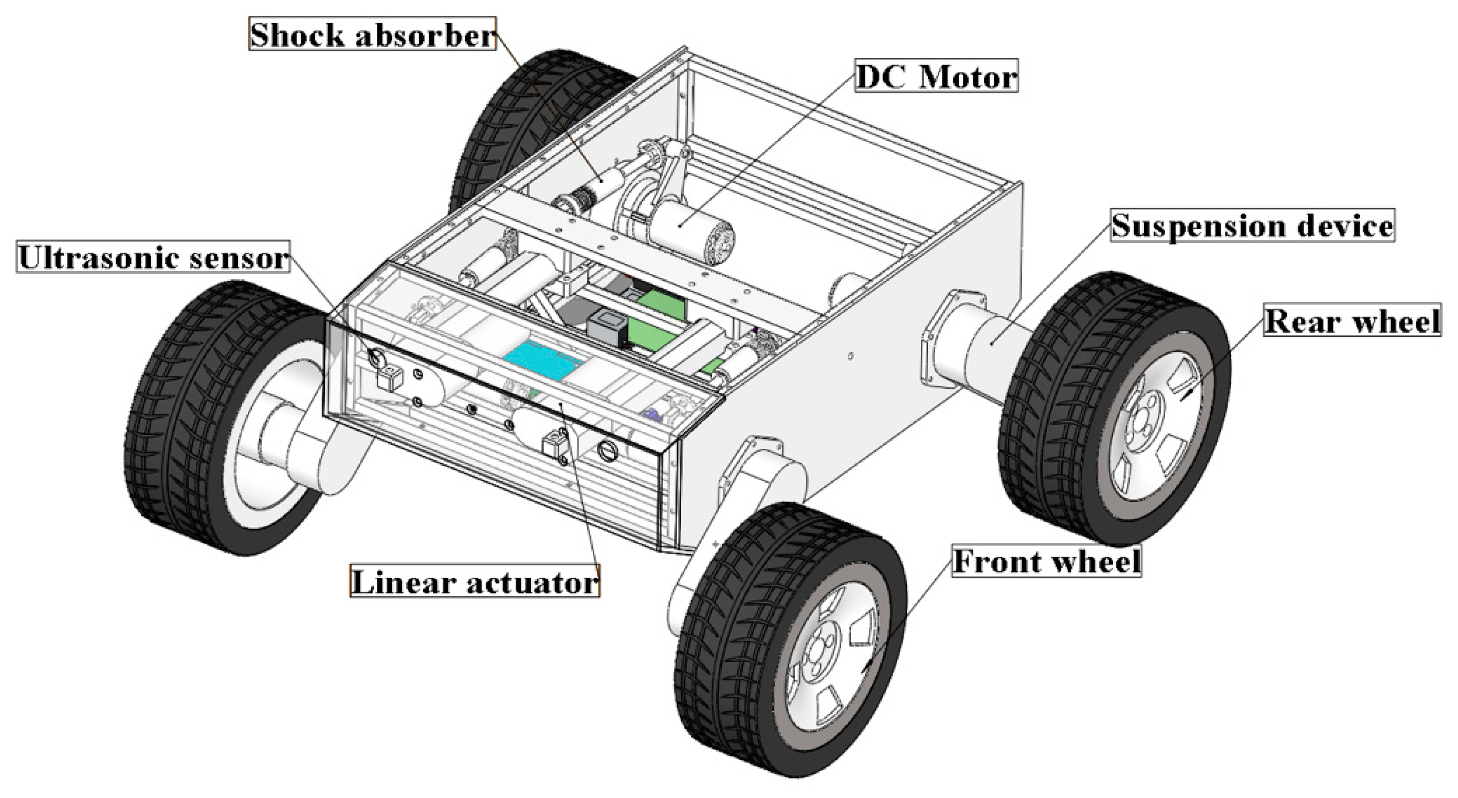
The WLHR designed in this paper is mainly composed of a mechanical system and a control system [
23], as shown in
Figure 1, which is a three-dimensional (3D) model of the mechanical structure of the robot.
The WLHR is equipped with four wheel-leg suspension devices symmetrically on the left and right sides of the car body, and each wheel has rubber tires with patterns on the outside to increase the friction between the wheels and the ground, and prevent the skidding phenomenon in the process of obstacle crossing. Each wheel-leg suspension device is equipped with a DC brushless motor, which is driven by C620 and placed on the inside of the car body. The ultrasonic sensor is placed on the front baffle and rear baffle of WLHR to sense the existence of obstacles. The linear actuator is placed on the front side of the WLHR and fixed with the two suspension devices in front of the robot to drive the movement of the leg suspension mechanism.
Considering the quality problem of the linear actuator, if the lithium cell is placed in the middle position, it may cause the center of gravity to move forward. To prevent the WLHR from overturning due to the unstable center of gravity in process of movement and obstacle crossing, the lithium cell should be placed on the rear side of the platform. Place the master control board in the center of the platform to facilitate connection with various electrical devices.
2.2. Suspension Device Design
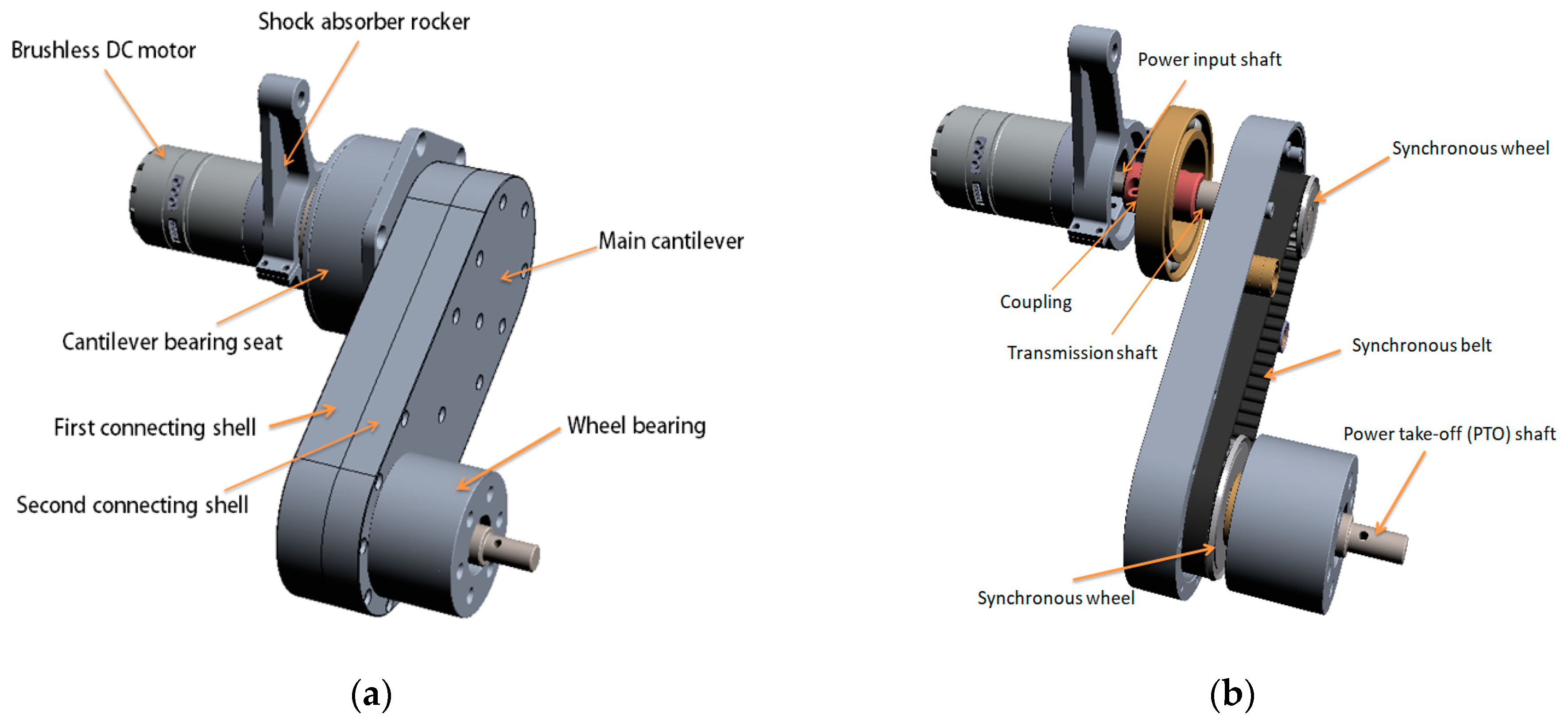
The composition diagram of the suspension device is shown in
Figure 2.
The suspension device is placed in the body, which is composed of a brushless DC motor, shock absorber rocker, cantilever bearing seat, main cantilever, and wheel bearing. The motor is connected with the cantilever bearing seat, and the motor is provided with a power input shaft, which is connected with one end of the transmission shaft through a coupling to drive the transmission shaft to rotate; the power take-off (PTO) shaft is connected with the bearing at the wheel to drive the wheel to rotate.
The leg transmission component, namely the main cantilever, is connected between the transmission shaft and the PTO shaft, and it mainly comprises a first connecting shell and a second connecting shell which are matched and connected, and an installation cavity which is defined by the first connecting shell and the second connecting shell; the driving wheel group, namely two synchronous wheels installed in the cavity, which drive the PTO shaft to rotate through the synchronous belt; and the first belt wheel, the second belt wheel, and the synchronous belt. The radial dimension of the first belt wheel is smaller than that of the second belt wheel; the synchronous belt is connected between the first belt wheel and the second belt wheel; the first belt wheel is connected with the transmission shaft; and the second belt wheel is connected with the PTO shaft.
4. Simulation and Analysis
ADAMS software is used to simulate the kinematics of the WLHR. Firstly, the 3D model established in Solidworks is imported into Adams, and the multiple models are simplified without affecting the results, which reduces the operation difficulty, and the simulation results are analyzed accordingly. The main technical parameters of the mechanism are shown in
Table 2.
4.1. Obstacle-Crossing Process Analysis
Climbing the stairs is a process in which the robot is continuously crossing obstacles, and it is also one of the difficult tasks that the all-terrain robot must complete [
24,
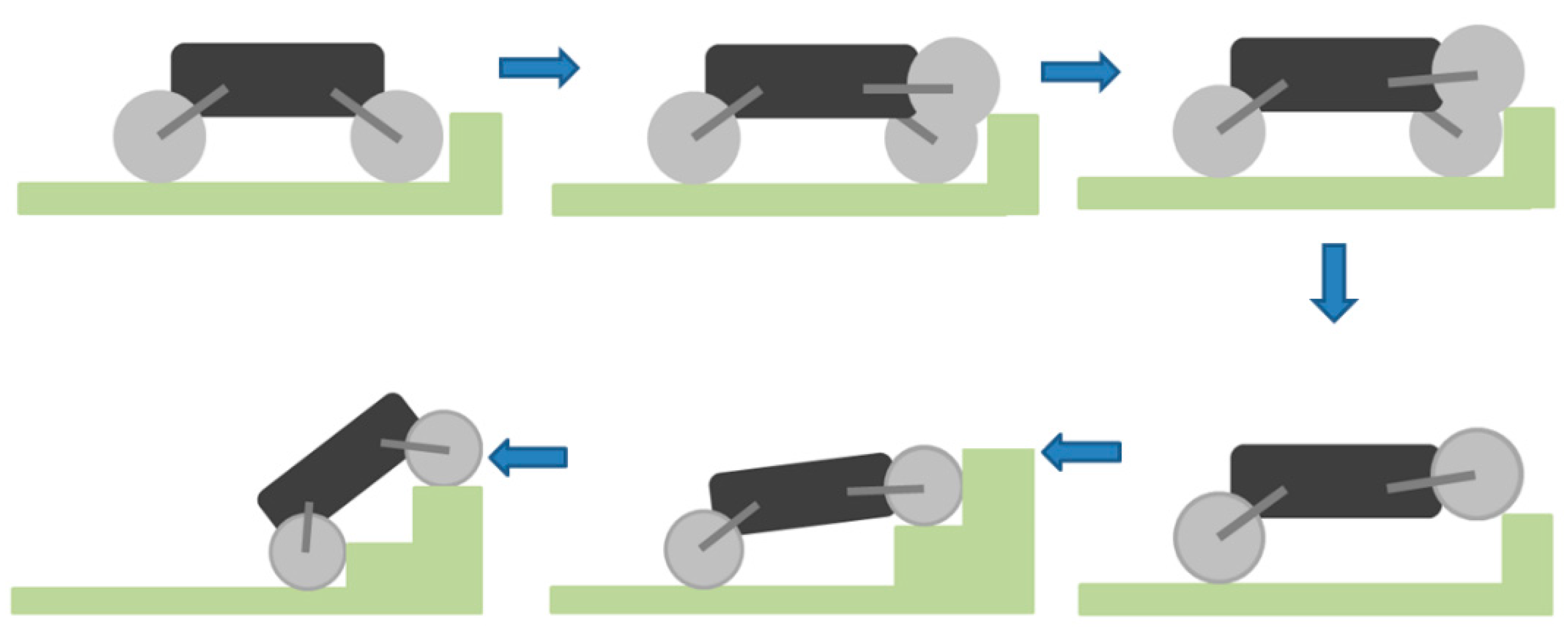
25]. In addition to the power of the robot itself, the key factors that influence the robot climbing the stairs are the torque and the specific parameters of the stairs. In the simulation model, the given stair height is 150 mm, and the stairs width is 260 mm. Referring to relevant design data, it can be seen that the designed stairs meet the ladder size of national standards. The process of the WLHR climbing the stairs is shown in
Figure 6.
WLHR uses a waterproof ultrasonic sensor to sense the existence of obstacles, and its blind area has broken through to 13.8 cm, with good sensing performance. Through the analysis of the obstacle crossing process of the robot, it can be seen that when the robot encounters obstacles in the process of moving, the ultrasonic sensor senses the existence of the obstacle, so that the robot stops moving forward at a certain distance from the obstacle, and the front wheel is lifted under the action of the suspension device. Assuming that the right-front wheel is lifted, WLHR continues to move forward for a certain distance to make the right-front wheel contact with the obstacle and generate interaction force. At this time, the right-front wheel moves and swings the leg back to lift WLHR. At the same time, the left-front wheel quickly completes the actions of front swing leg and rear swing leg, and completes the action of obstacle crossing together with the right-front wheel. If the front wheel can cross the obstacle smoothly, it can drive the fuselage and other wheels to cross the obstacle; if the front wheel cannot cross the obstacle, the whole body will fail. Therefore, when the size of the whole robot is limited in a certain range, the obstacle-crossing performance of the front wheel-legs of the robot will directly affect the obstacle-crossing ability of the whole robot.
4.2. Analysis of Obstacle Crossing Height
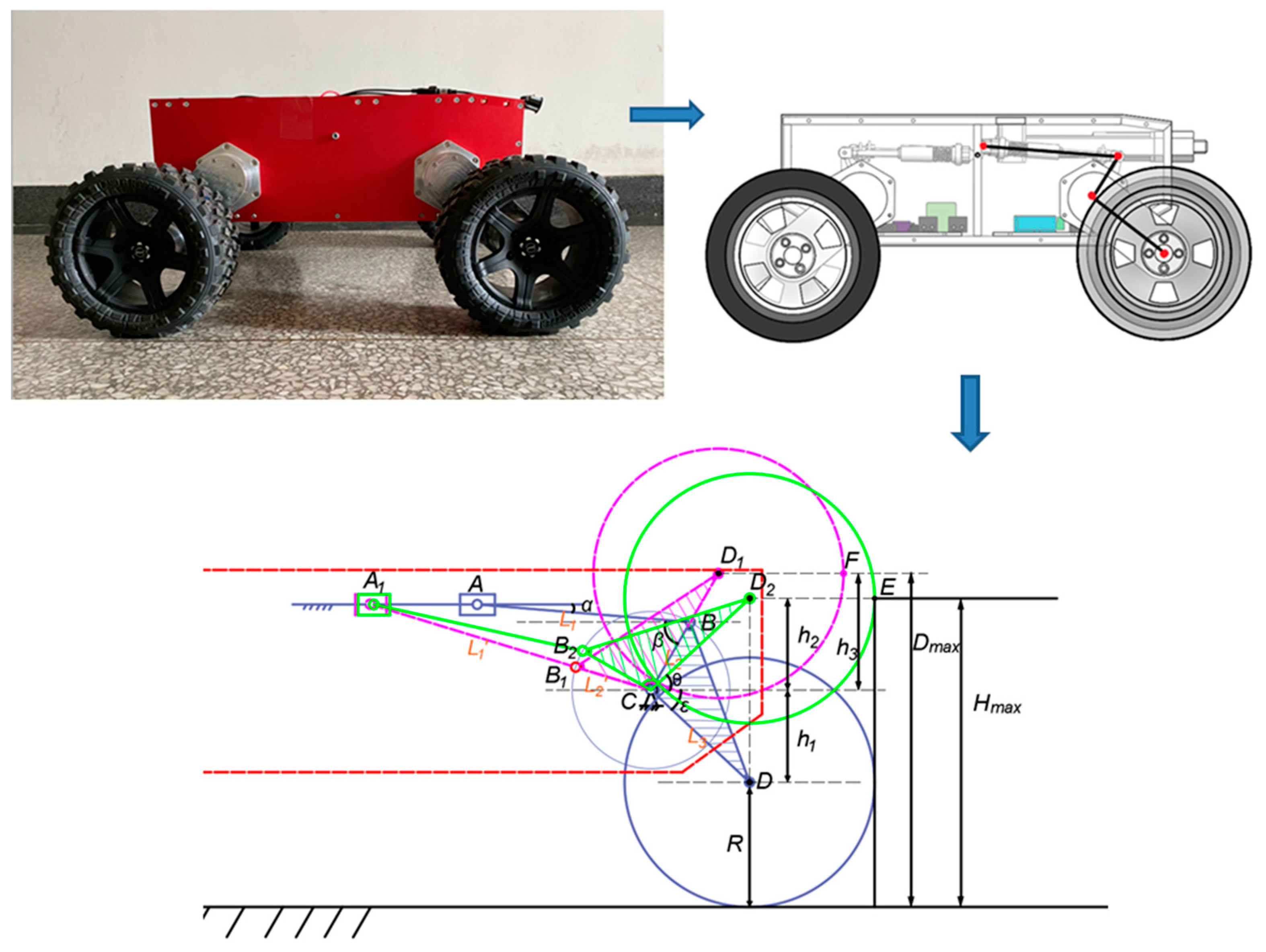
To analyze the obstacle crossing performance, it is necessary to study the obstacle crossing height of the front wheel of WLHR. Because the slider-crank mechanism is used in the structural design of the wheel-leg suspension mechanism, it is easier to simplify it into a mathematical model to analyze the obstacle crossing height.
Shown in
Figure 7 is the mathematical model analysis diagram of obstacle crossing height of front wheel legs.
The linear actuator is the slider A, the segment BC is the crank, and the segment AB is the connecting rod. The WLHR designed in this paper takes slider A as the driving links and crank BC as the driven links. Because its structure is a slider-crank mechanism, the existence of dead point position must be considered, and the forward stroke of linear actuator cannot exceed the dead point position. When the driven links crank BC is collinear with the connecting rod AB, the dead point position appears, that is, the segment .
When WLHR is ready to cross the obstacle, whether the left-front wheel or the right-front wheel swings first, the position of the un-lifted wheel in the vertical direction cannot exceed the position of the lifted wheel in the vertical direction, otherwise the swinging wheel will not touch the obstacle.
It is assumed that the position below the front side of the wheel in contact with the obstacle is taken as the obstacle crossing height. It can be seen from
Figure 7 that the height of the contact point E between the wheel and the obstacle represented by the green line is the maximum height that WLHR can actively cross the obstacle.
The letter symbols used in the analysis process are shown in
Table 3.
According to the knowledge of trigonometric function:
According to the actual measured value, , , , , , . Bringing the actual measured values into Equations (10)–(15), we can calculate that , . Since the wheel needs to have contact force with obstacles, the climbing height needs to be less than 281 mm.
It can be seen from the above analysis that the maximum obstacle crossing height of WLHR is related to factors such as the length of suspension device, wheel radius, and its related included angle.
4.3. Simulation Experiment of WLHR on the Complex Road Surface
Stability is an important index to evaluate the operation ability of WLHR [
26]. Locomotion on flat and complex roads or slope terrain can be simply and effectively performed by wheels with high speed and energy efficiency. When crossing higher obstacles such as stairs, according to the process described in the obstacle crossing process diagram in
Section 4.1, the obstacles can be stably crossed by mutual movement of wheels and legs.
Figure 8 shows the simulation process in ADAMS.
Figure 8a provides the simulation diagram of the operation process of the robot on the complex road surface, including concave and convex slopes and obstacles.
Figure 8b shows the simulation diagram of the operation process of the robot climbing stairs.
Figure 8c shows the simulation diagram of the operation process of the robot on slope terrain.
Figure 8d shows the simulation diagram of the left and right wheels of the robot continuously crossing obstacles. After the simulation runs, the velocity, centroid displacement, and acceleration curves of the robot can be obtained through the post-processing module of the software.
Figure 9a shows the change curve of centroid displacement when the robot moves on the complex road surface. It can be seen from
Figure 9a that the displacement of the robot normally crossing the complex road is roughly consistent with the height of obstacles, with little fluctuation.
Figure 9b shows the change curve of centroid acceleration when the robot moves on the complex road surface. It can be seen from
Figure 9b that the acceleration changes obviously when the robot climbs over obstacles, the forward speed decreases when climbing the obstacle, and the speed returns to normal after climbing the obstacle.
Figure 10a shows the centroid displacement curve of the robot climbing the steps. It can be seen from
Figure 10a that the robot climbs the steps for 3.2 min 5 s to 10 s, the robot climbs the steps steadily, and there is no obvious carton when climbing the stairs. The fluctuation of the robot centroid is small, which proves that the robot climbs the stairs with good stability.
Figure 10b shows the acceleration of the robot centroid of mass in X, Y, and Z directions. It can be seen from
Figure 10b that the acceleration of the robot remains at approximately 0 while climbing the steps, indicating that the robot is almost advancing at a stable speed; there is a small sudden change in acceleration at 6.5 s, which is the moment when the front leg of the robot just touches the stairs; there is a sudden change in the acceleration from 6 s to 7 s; and three directions occur at the same time. Therefore, it is inferred that the contact between the rear wheel of the robot and the step surface produces relative sliding.
The slope angle of climbing simulation experiment is 35° and the height is 0.56 m, which meets the technical parameters required by the project.
Figure 11a shows the centroid displacement curve of the robot in the moving process of slope terrain. WLHR starts moving in slope terrain at 5 s. According to the smoothness of the curve, it has good stability and almost no fluctuation in the centroid.
Figure 11b shows the change process of centroid acceleration curve of the robot during moving in slope terrain. From 0 s to 12 s, the centroid acceleration is approximately 0, which reflects the good stability and fast passing ability of the robot when moving in slope terrain. At 12 s, there is a sudden change in centroid acceleration, which is the reason why the robot meets obstacles on the plane after going downhill. The simulation results are completely consistent with the actual movement.
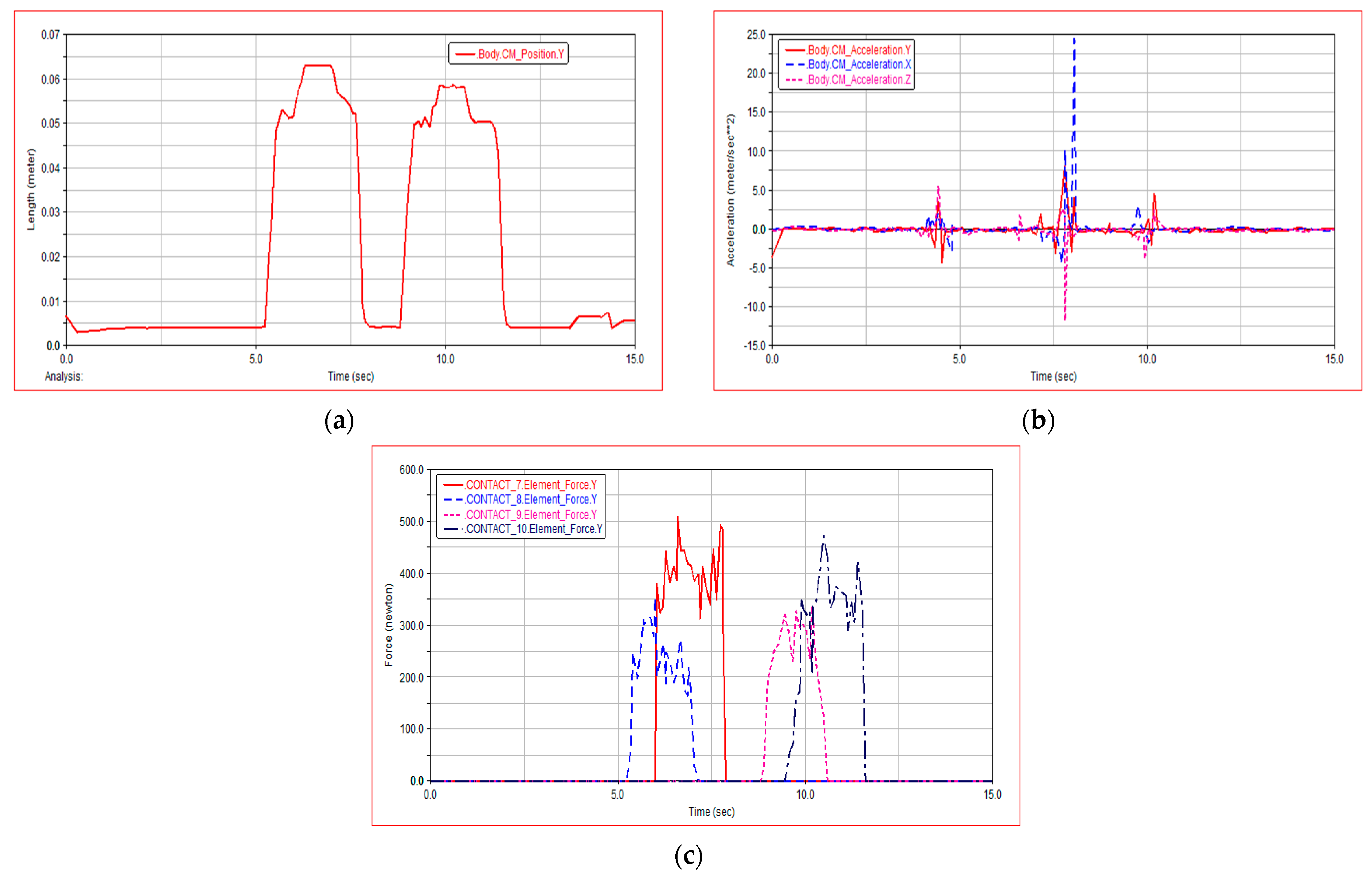
Figure 12a shows the change curve of centroid displacement when both sides of the robot are obstacle crossing continuously. During the simulation period of 5 s to 12 s, the change of centroid displacement is almost the same when the left side of the robot continuously obstacle crossing and the right side continuously obstacle crossing, which verifies the rationality of WLHR symmetry design. It can be seen from
Figure 12b that the centroid acceleration is also approximately equal to 0, and only slightly changes when meeting obstacles and obstacle crossing, which proves that WLHR has good lateral stability.
Figure 12c shows the force changes of the left and right wheels during continuous obstacle crossing. When the left wheel continues to obstacle crossing, the force on the right wheel increases, and the force on the left wheel decreases. When the right wheel continues to obstacle crossing, the force on the left wheel increases, and the force on the right wheel decreases. This motion process conforms to the model that both sides of the robot continuously obstacle crossing, which verifies the stability of the robot.
The result proves that the robot can stably complete the motion on flat and complex roads, slope terrain, and the climbing steps and obstacle crossing functions, which verifies that the robot structure design is rational and simple.
Through simulation and analysis, compared with other WLHR proposed in the previous scientific literature, it has similarities and differences, but it still has its unique features.
The WLHR system designed in this paper has similarities with BIT-NAZA [
10], such as independent driving wheel-leg mechanism and high stability but shows the following differences: (i) BIT-NAZA has a higher body height and better passing ability and (ii) both are symmetrical structures, but BIT-NAZA can change the symmetrical width of the legs.
Regarding the wheeled locomotion, there are some similarities with the ANYmal [
20]: (i) The wheels are placed at the end of rotating arms and the steering motion adopts differential rotation; (ii) the most compact and robust design.
5. Prototype Verification
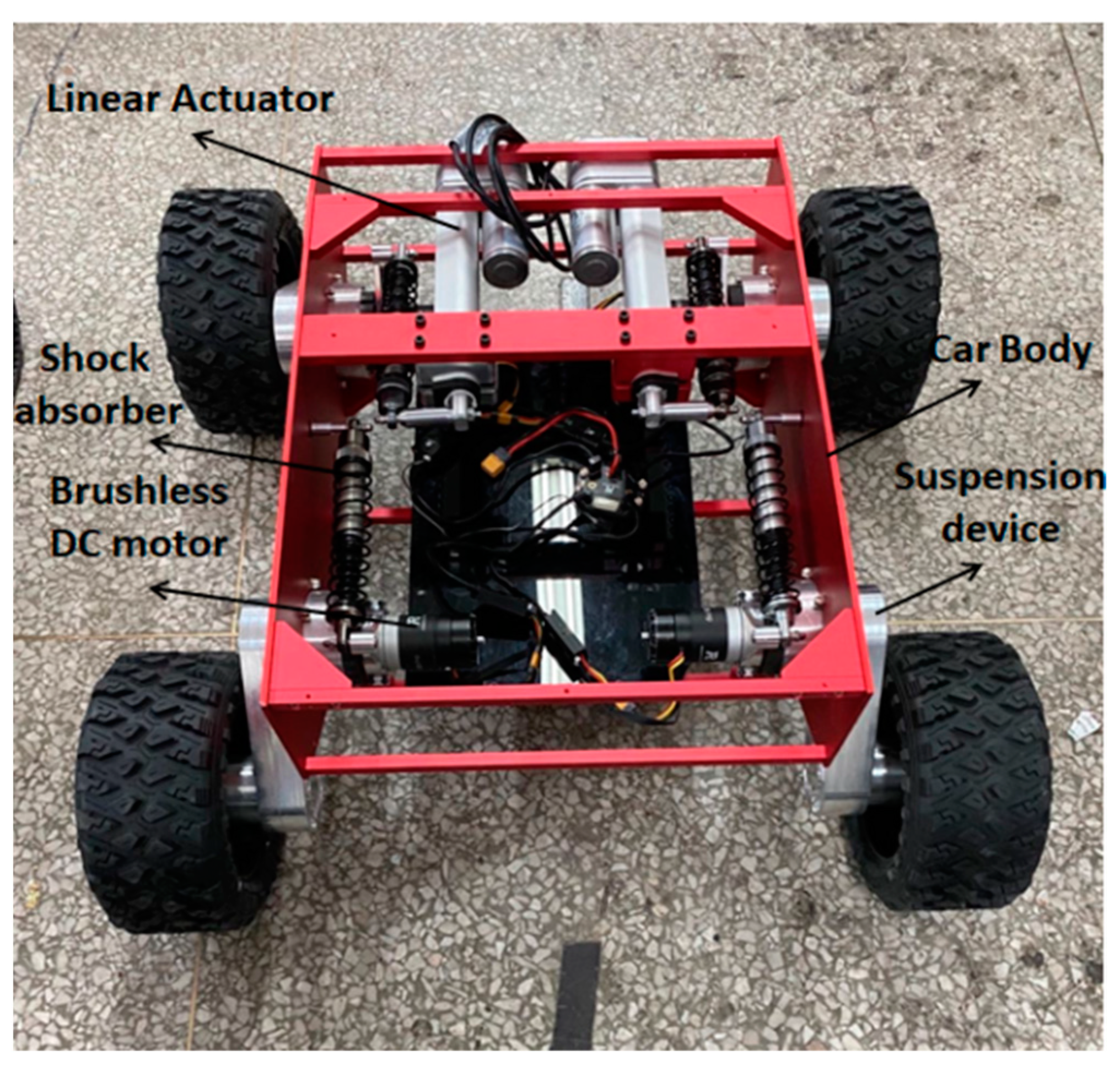
A prototype is made to verify the function and mobile ability of the proposed WLHR, as shown in
Figure 13. Through the obstacle avoidance function test, the perception ability of the robot is verified. The mobile ability of the prototype was tested in different situations, including the vertical obstacle crossing experiment, continuous step climbing experiment, and grassland passing experiment.
5.1. Analysis of Obstacle Avoidance Experiment
This paper adopts an ultrasonic sensor, which can not only provide perception when obstacle crossing, but also provide obstacle avoidance function when WLHR cannot cross the obstacle.
The principle of obstacle avoidance of ultrasonic sensor is based on the relationship between sound velocity, time, and obstacle distance. The expressions of the three can be expressed as follows [
27]:
In the above expression, C represents the velocity of sound; S represents the distance between WLHR and obstacles; and T represents the time difference between the time of transmitting pulse and the time when the first echo arrives.
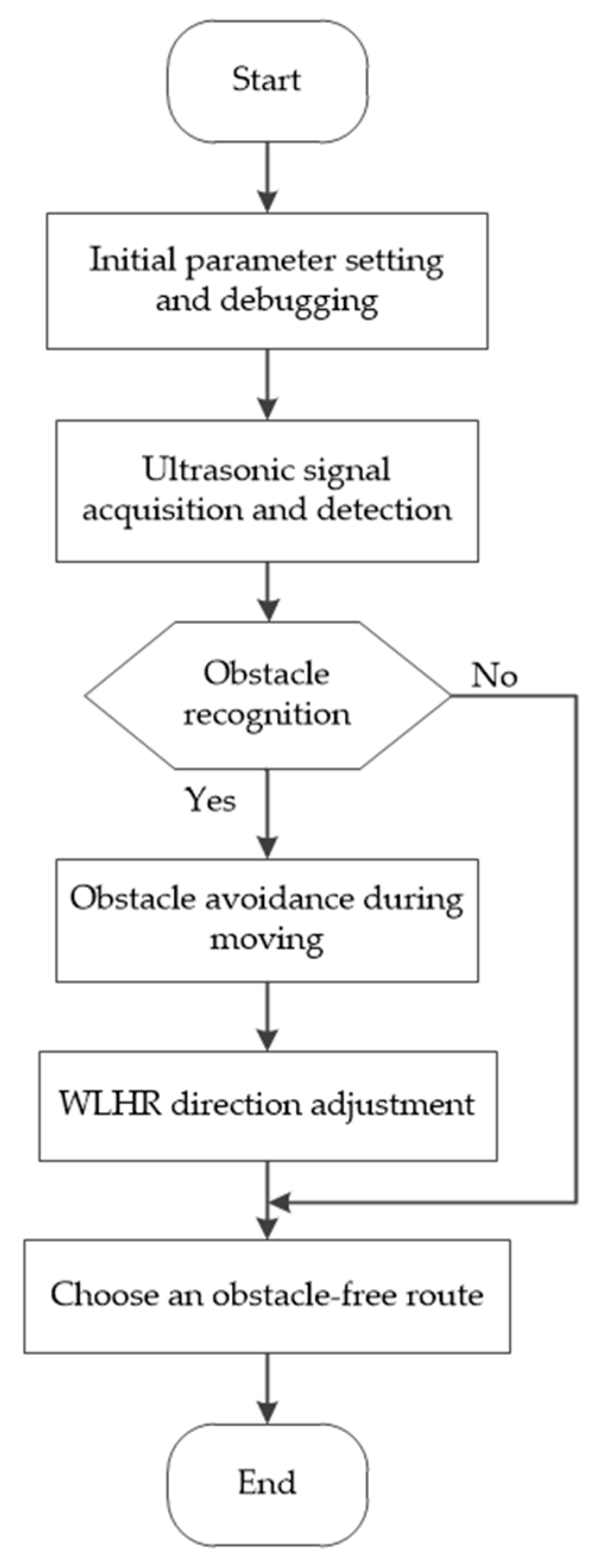
With the help of fuzzy reasoning and control, the accuracy of obstacle avoidance algorithm in application is strengthened, which is convenient for WLHR to identify and control obstacles. Taking the designed ultrasonic obstacle avoidance algorithm as an example, the main operation process of WLHR is shown in
Figure 14.
As shown in
Figure 14, when WLHR works, firstly, initialize the parameters and adjust the obstacle avoidance parameters of WLHR, so that the WLHR can select the obstacle free route within a safe distance in time. Then, the ultrasonic sensor is used to collect the acoustic signal around WLHR, detect the distance between WLHR and obstacles, compare the data with the set data, and select a reliable operation route. When meeting obstacles, WLHR avoids obstacles, rotates at an appropriate angle, and continues to choose safe driving. If WLHR does not detect obstacles, it can directly choose to go straight without obstacles to complete the specified tasks.
Figure 15 shows the sensing diagram of WLHR ultrasonic sensor.
The beam angle of the ultrasonic sensor in the vertical direction is 60°, and the installation position is at the front baffle of WLHR, with a height of 280 mm from the ground. The height between the car body and the ground designed in this paper is 300 mm. The maximum obstacle crossing height is , which is just the same as the installation height of ultrasonic sensor. Therefore, when the sensing height of the ultrasonic sensor is higher than 280 mm, WLHR avoids obstacles; when the sensing height of the ultrasonic sensor is lower than 280 mm, WLHR will cross the obstacle.
Sensing the distance of obstacles is the key to obstacle avoidance. Therefore, it is very important to test the obstacle avoidance distance of the prototype. Shown in
Table 4 is a test of the distance of perceptible obstacles.
It can be seen from the table that WLHR has high perception sensitivity, and the maximum distance of obstacles that can be detected is 400 cm.
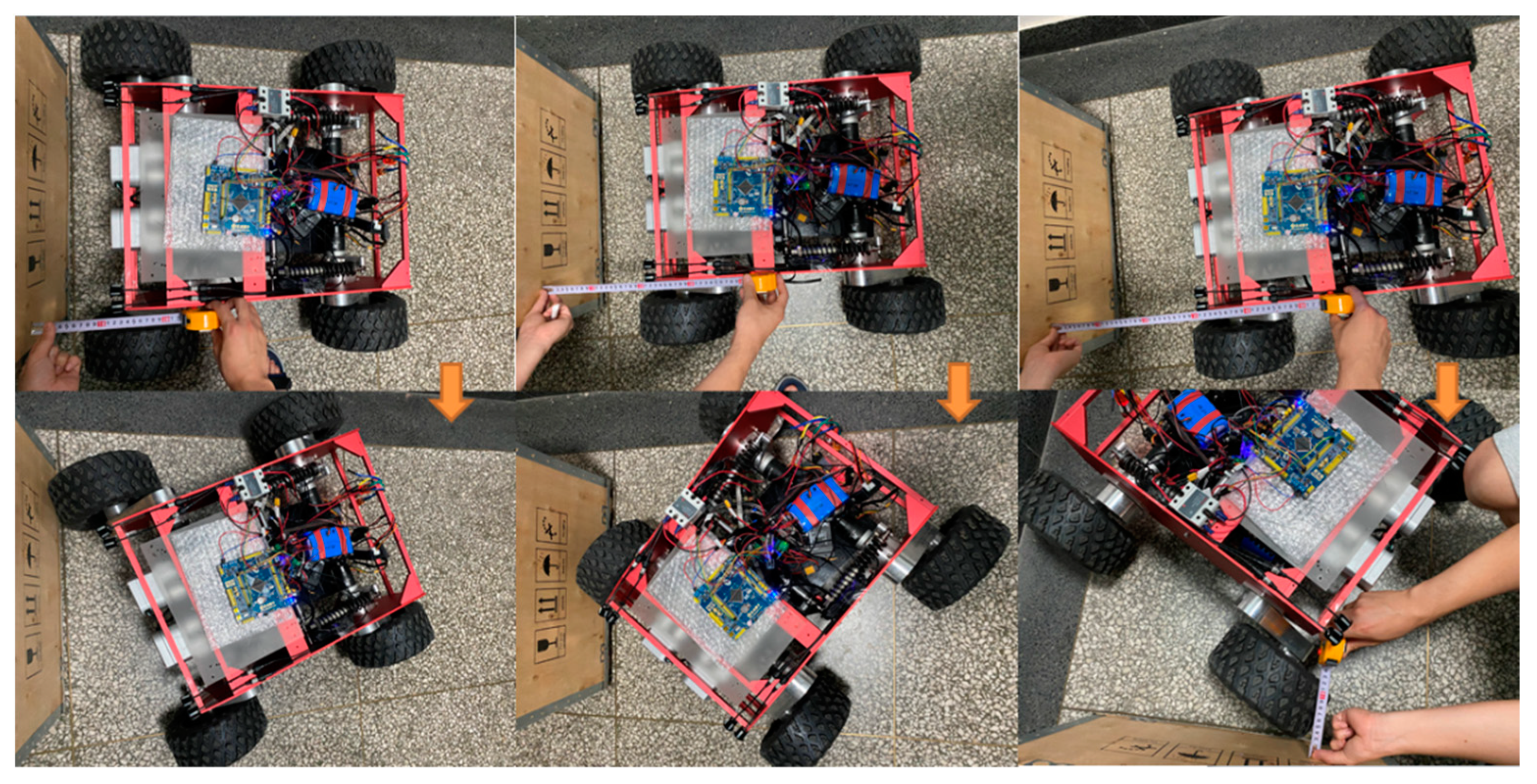
Since WLHR is differential motion, it is necessary to consider the appropriate position to stop when sensing obstacles. Otherwise, WLHR will collide with the obstacle during turning.
In the prototype obstacle avoidance experiment, it is assumed that the width of the obstacle is the same as that of WLHR, which is D. The test environment of the prototype is set on a relatively smooth ground. Because the friction coefficient varies according to different terrain, the minimum turning distance during obstacle avoidance will also be different.
Shown in
Figure 16 is the minimum distance experiment that the prototype can turn successfully when avoiding obstacles. Shown in
Table 5 is the minimum obstacle avoidance distance in which WLHR can complete turning under the condition of width D.
5.2. Prototype Experiment in Complex Terrain Environment
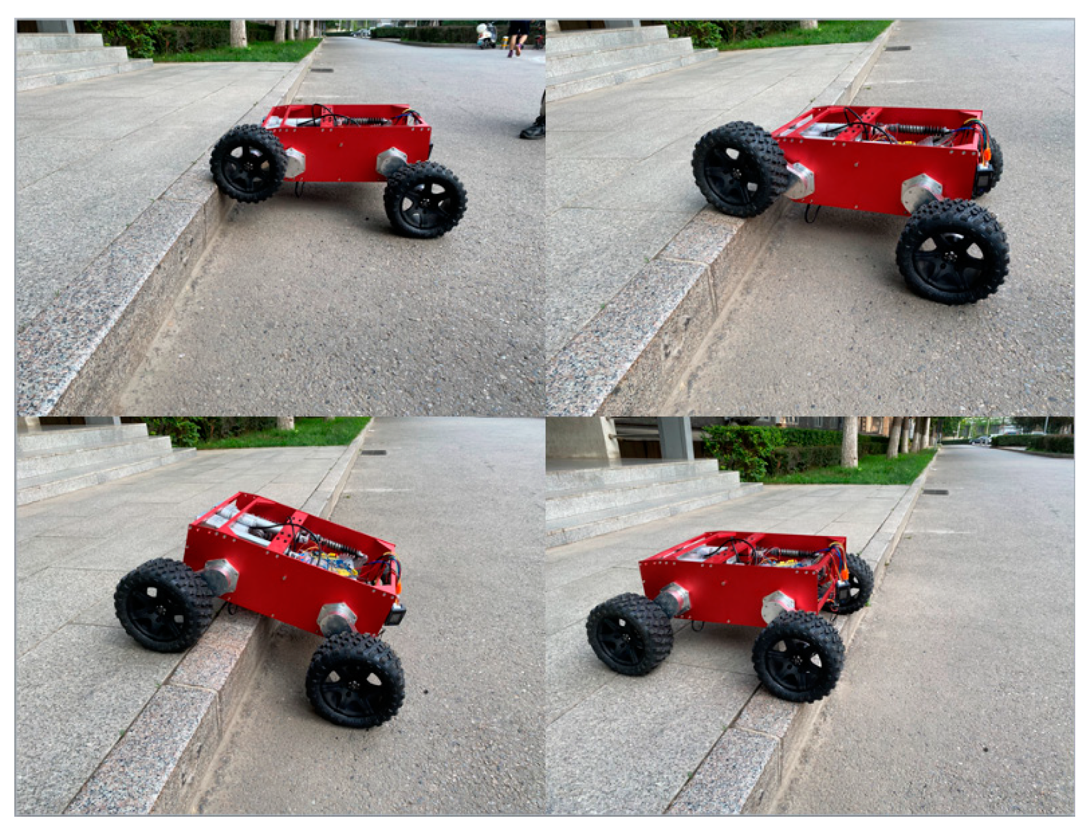
As shown in
Figure 17, the robot is conducting a vertical obstacle crossing experiment, and the linear actuator pushes the suspension device to drive the wheel to lift through the obstacle. The experiment shows that the obstacle crossing height of the mechanism is 150 mm.
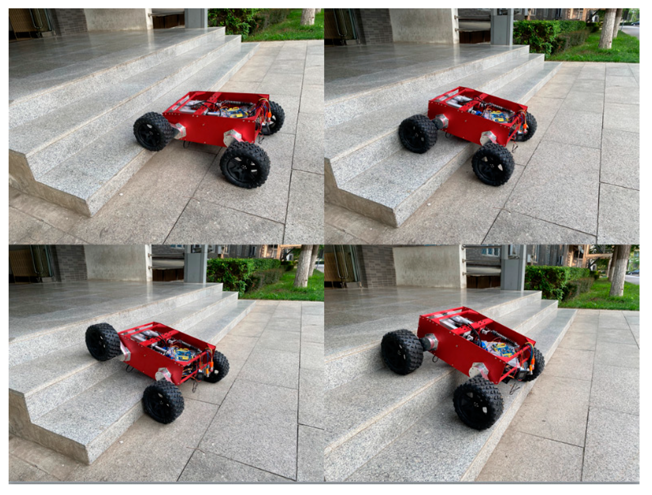
As shown in
Figure 18, the robot is conducting the continuous step climbing experiment. The experiment shows that the WLHR has the ability of continuous obstacle crossing, and the dimension of continuous step is 250 mm tread wide and 160 mm tread heigh.
As shown in
Figure 19, the robot passes the experiment in the grassland. The elastic restoring force of the self-adaptive mechanism can make the WLHR walk stably in the irregular terrain, and the fluctuation of the centroid is small, which proves that the mechanism has good passing ability in the complex terrain.
Through the prototype experiment, it is found that the WLHR has excellent adaptive ability and sensitive perception ability, and it has high trafficability on the various complex ground, which meets the all-terrain operation conditions. The motion process is consistent with the theoretical analysis.
6. Conclusions
In this paper, a WLHR that can adapt to an all-terrain environment was designed and implemented. It has both the mobility of wheel robot and the obstacle crossing ability of leg robot. The research process was as follows:
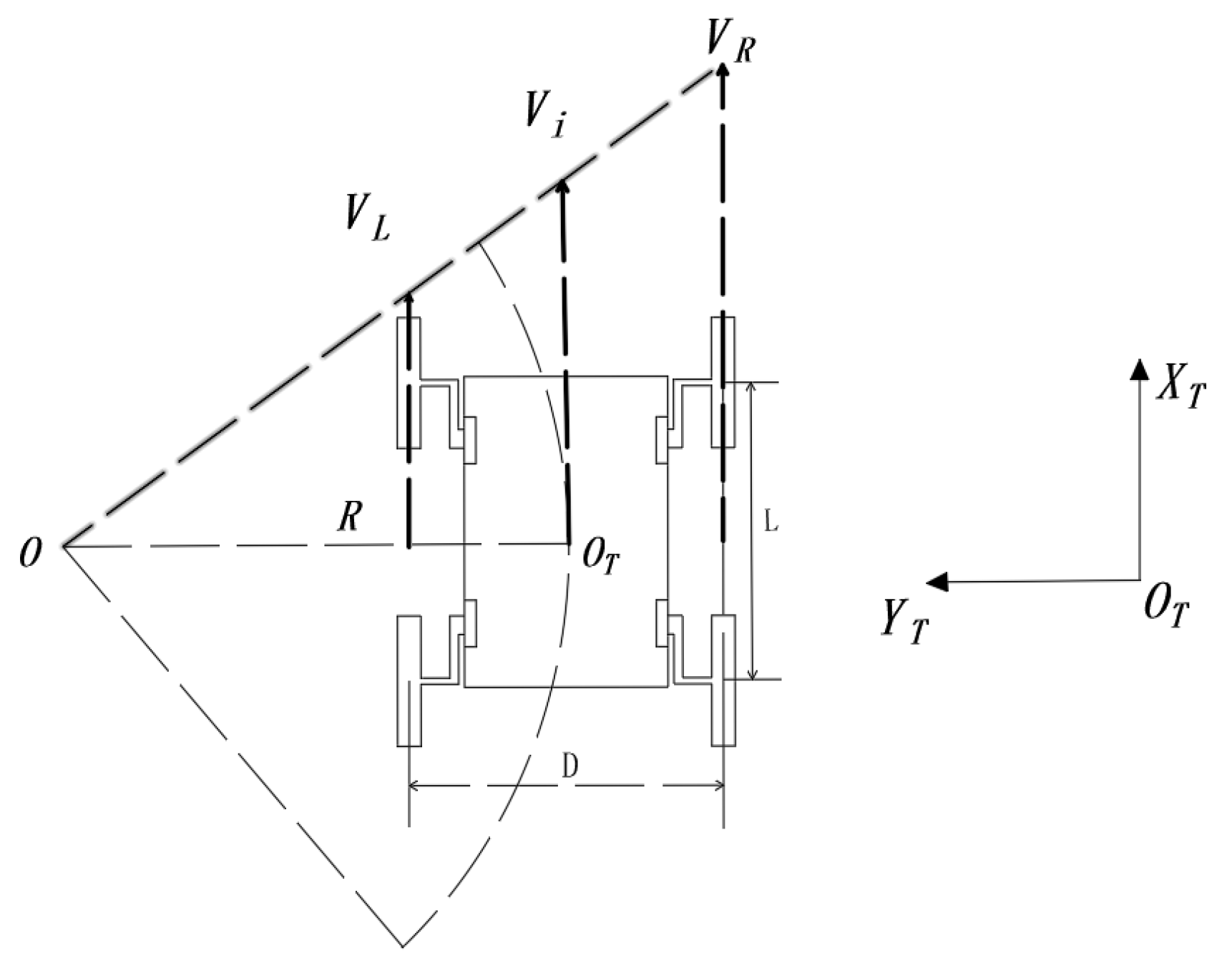
Firstly, the overall structure design and steering performance analysis were carried out, and the kinematics model was established to analyze the motion state of the robot.
Secondly, the maximum height of WLHR obstacle crossing was analyzed by mathematical modeling, and the maximum height was obtained. The kinematics simulation of the WLHR in different environments was carried out by ADAMS software, and the corresponding kinematics curves were obtained.
Finally, the experiments of obstacle avoidance and fast walking on flat ground, steering, obstacle crossing, and stair climbing were carried out on the prototype robot, which verifies the feasibility and practicability of the WLHR designed in this paper.
