Design and Implementation of the MIMO–COOK Scheme Using an Image Sensor for Long-Range Communication


Abstract
:1. Introduction
- Visible light waves do not have any negative influences on the human body [6]. In contrast, RF waves adversely affect human health and reduce system performance because of electromagnetic interference (EMI).
- The bandwidth of the visible light wave is much greater than that of the RF bandwidth; it is more than 1000 times the RF bandwidth.
- It is important to consider that when the line-of-sight transmission is gained by the channel model, visible light waves are more safe and efficient.
- The updated VLC modes are used in the IEEE 802.157-2011 standard [8].
- OCC uses cameras or image sensors to receive signals from a light source by using various modulation techniques.
- Light-emitting diode (LED) identification is a low-speed communication scheme with speeds below 1 Mbps; LEDs are used as photodiodes.
- Light fidelity (Li-Fi) is a high-speed modulation scheme that uses a high-rate photodiode with data exceeding 1 Mbps in the physical layer.
2. Contributions of This Research
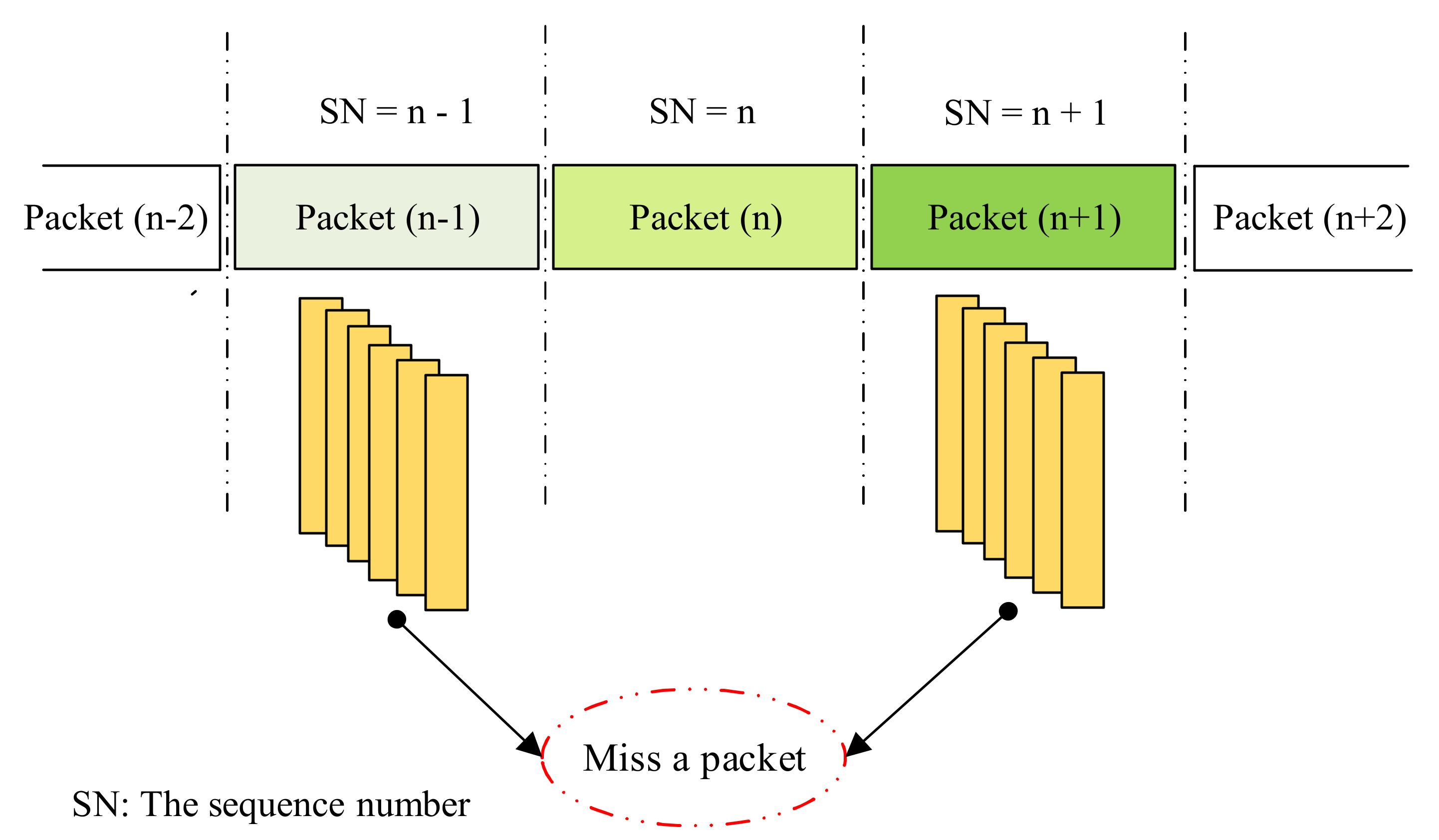
- Frame rate variation support: frame rate variations have an important effect on the OCC system; packets can be missed when decoding data on the receiver side. Most people believe that the camera frame rate is constantly similar to the camera specifications (e.g., 30 fps or 1000 fps). It is very difficult to synchronize the transmitter (Tx) and the receiver (Rx) depending on the technical parameters of the different cameras. The sequence number (SN) will improve the system performance by checking whether it has a frame rate larger than the packet rate of the transmitter.
- Detection of missing packets: we used two consecutive images captured by the camera to easily detect each missing packet by comparing two SNs when the length of the SN exceeded a certain value. A comparison of the SN and Ab bit to detect missing packets in the COOK scheme is presented in Section 4.
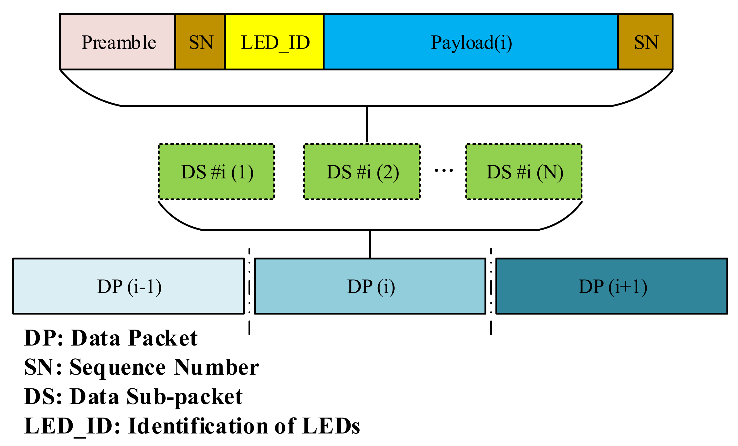
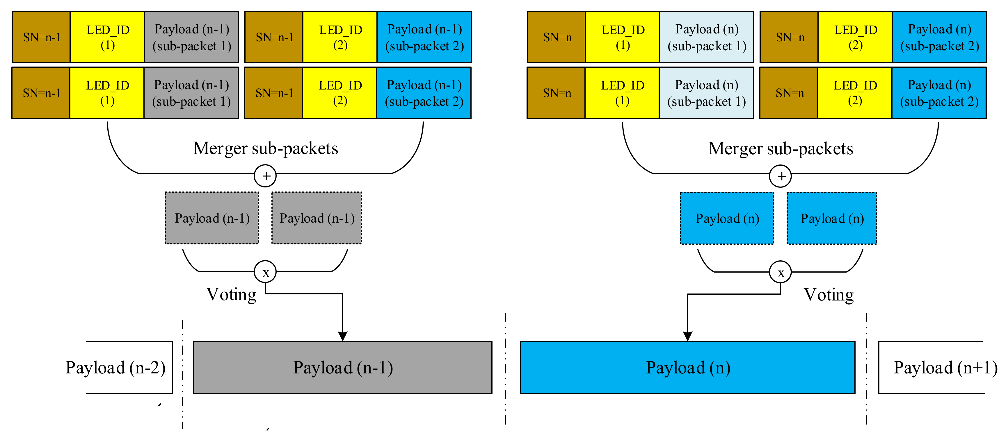
- Data merger algorithm: in our experiment, we proposed this algorithm for each data sequence by compacting the packages into it in the exact order. In this scheme, we used the SN to combine the data packets such as the Ab bit.
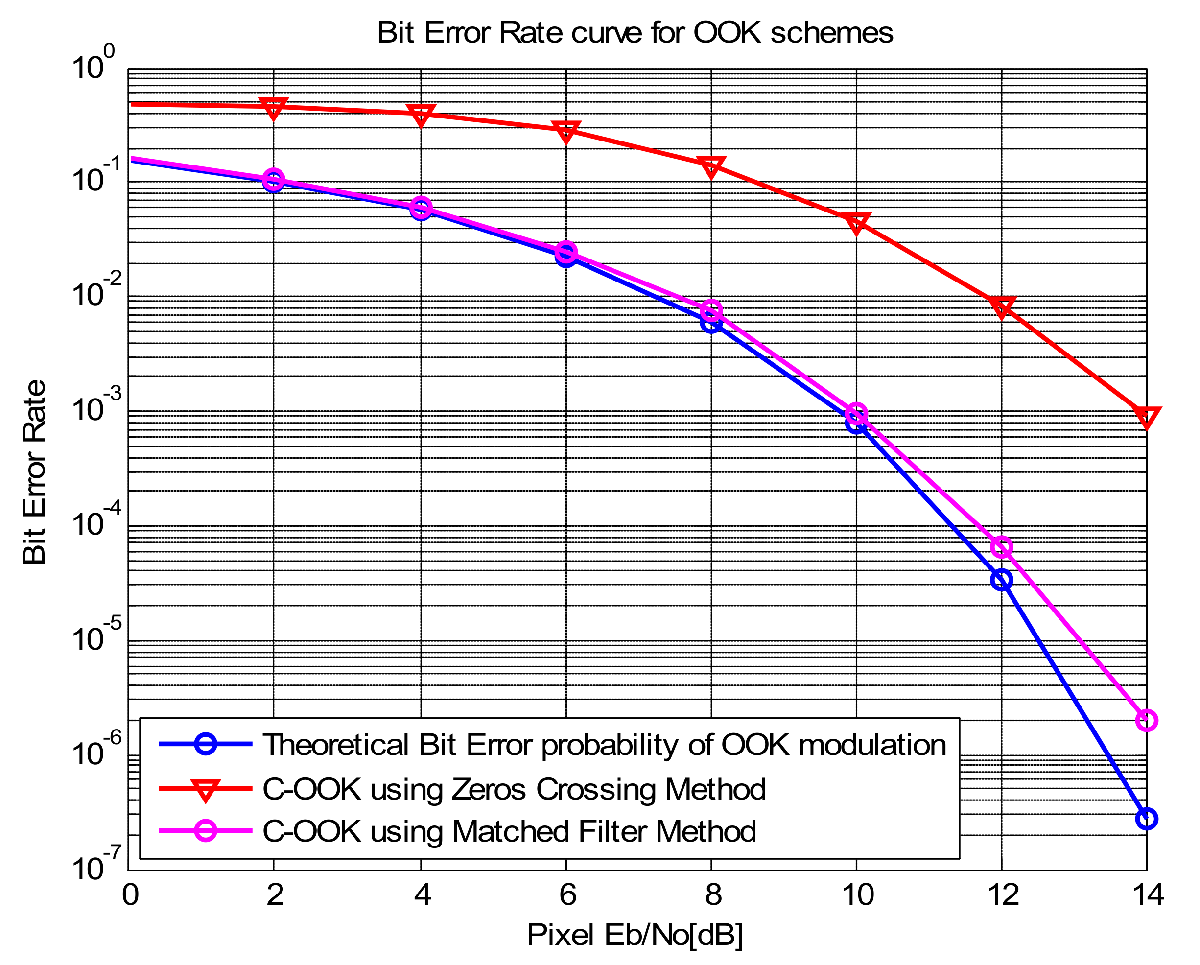
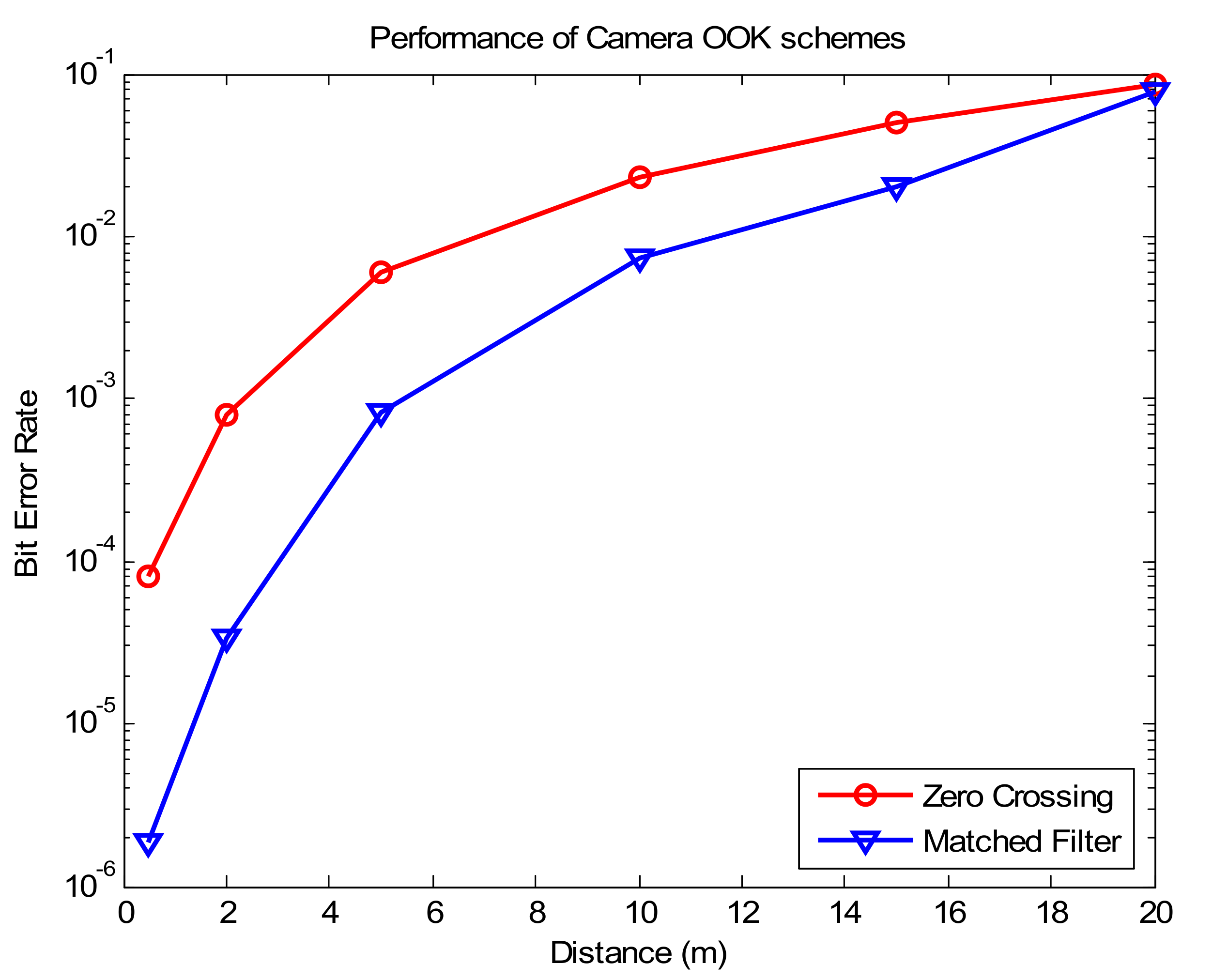
- Improve system performance as compared with the conventional COOK: a matched filter is the optimal linear filter for maximizing the SNR. For determining the on/off thresholds in images, the matched filter is superior to the conventional zero-crossing filter. The SNR is maximized; therefore, the communication distance also is increased, and we can achieve the desired BER. This will be shown in Section 3.3.
- Improved data rate: using multi-LEDs, the data rate will be increased as compared with the conventional COOK. Multi-LEDs are used to transmit data; therefore, RoI signaling is chosen to detect quickly the light sources in images corresponding to each LED.
- Improve the communication distance: by using the matched filter to detect the start of frame and decode data, the communication distance is improved than the conventional COOK (using Zero Crossing) because of its SNR improvement.
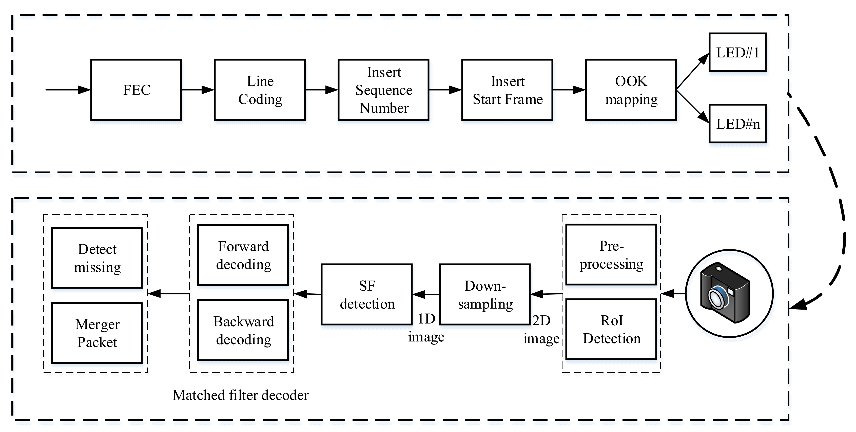
3. System Architecture
3.1. Line Coding
3.2. RoI Detection
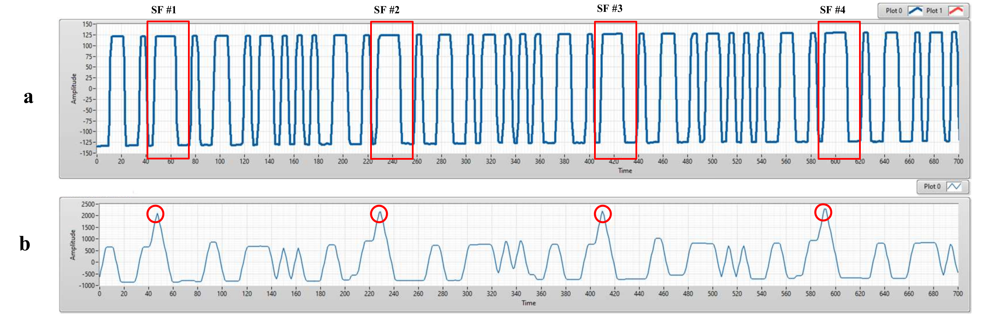
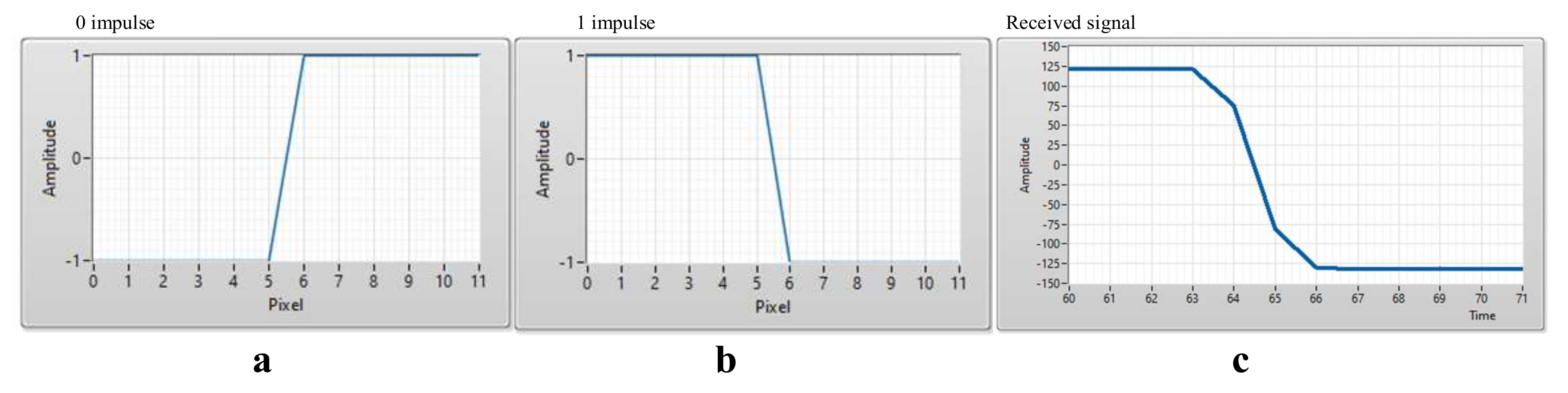
3.3. Match Filter
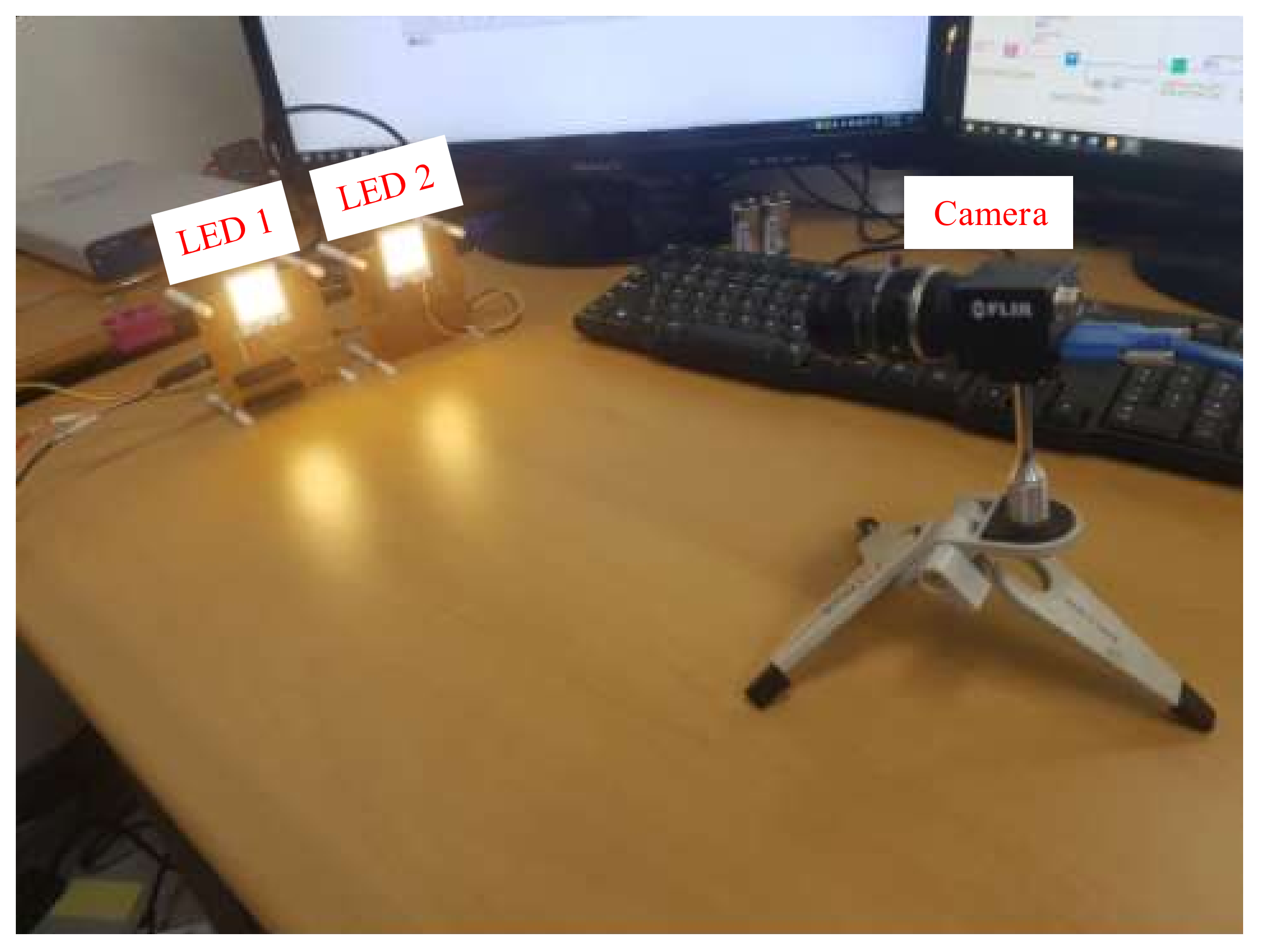
4. Implementation
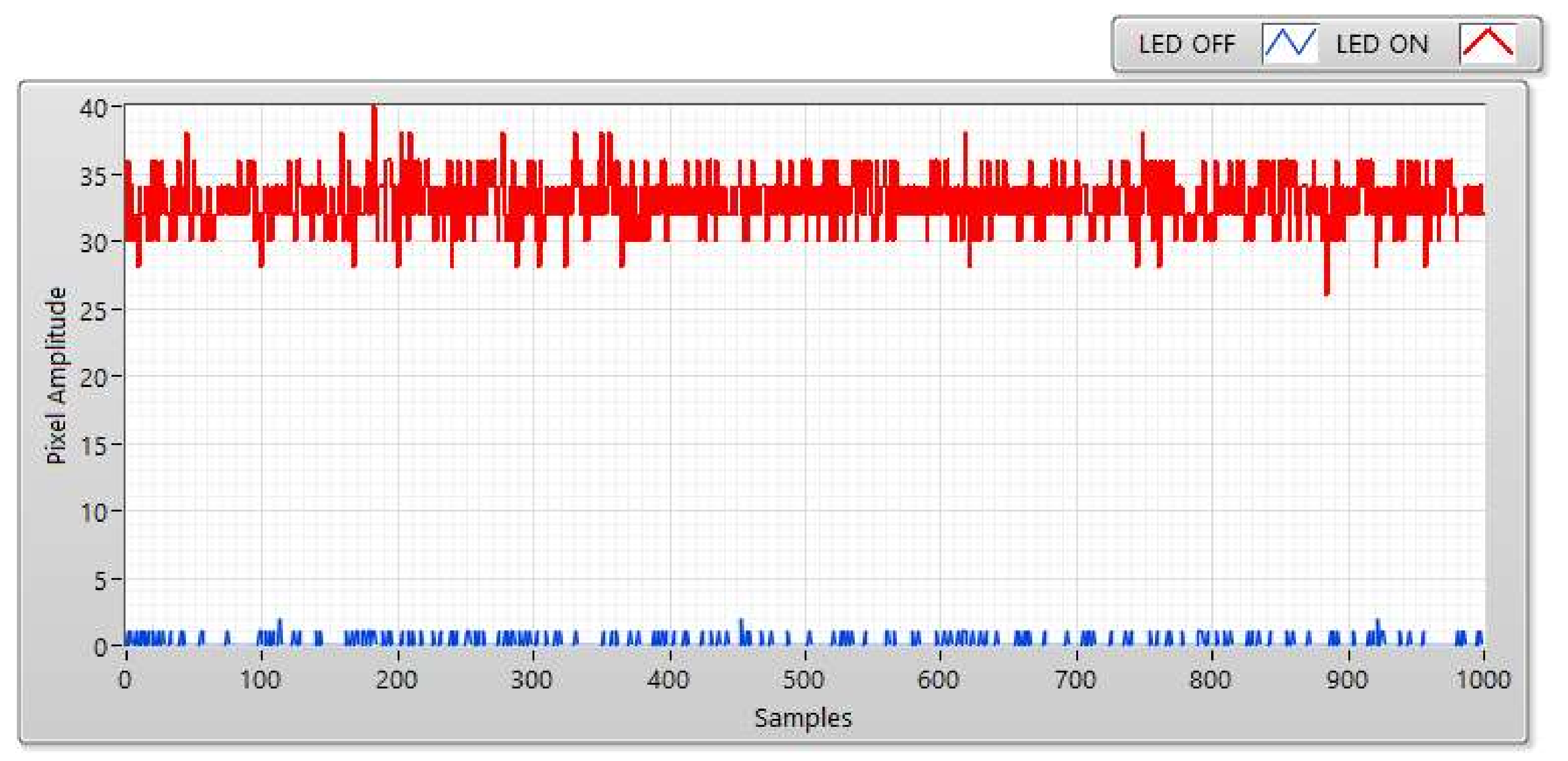
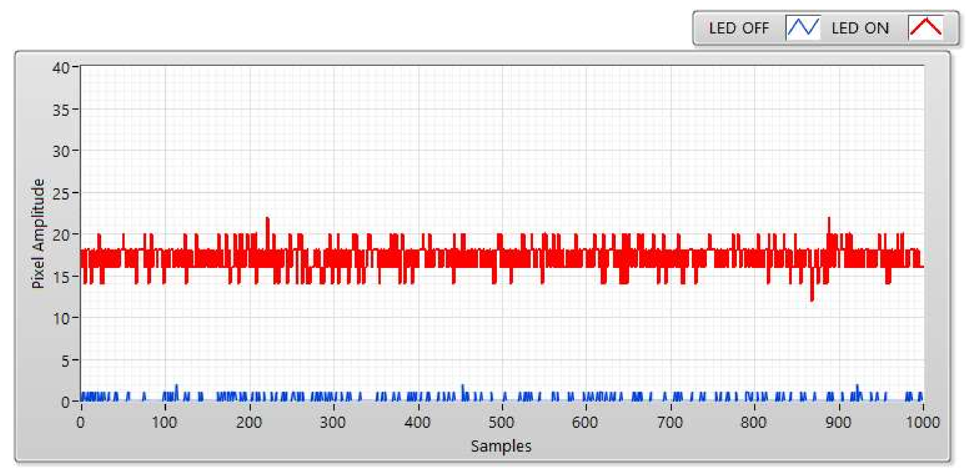
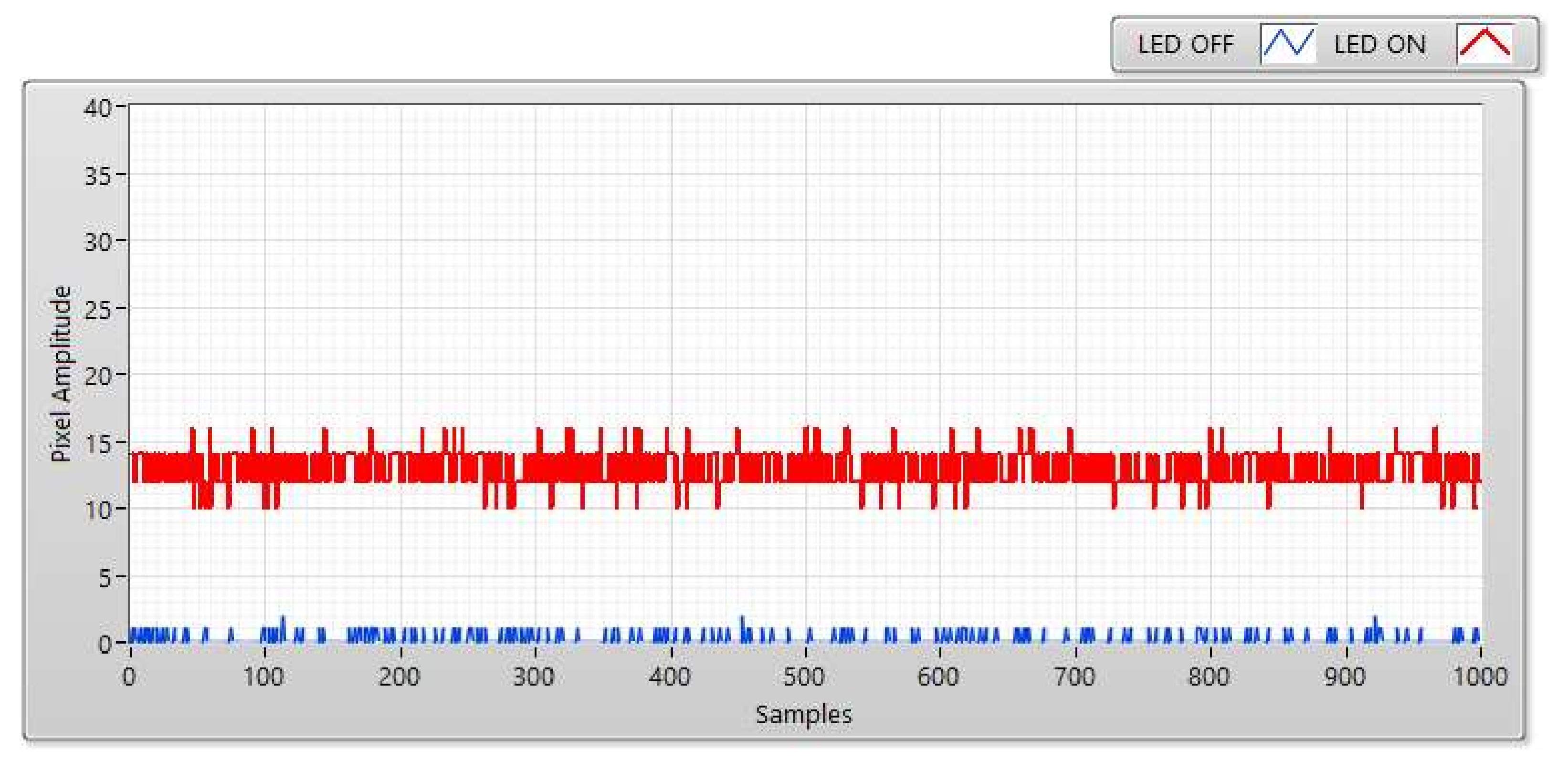
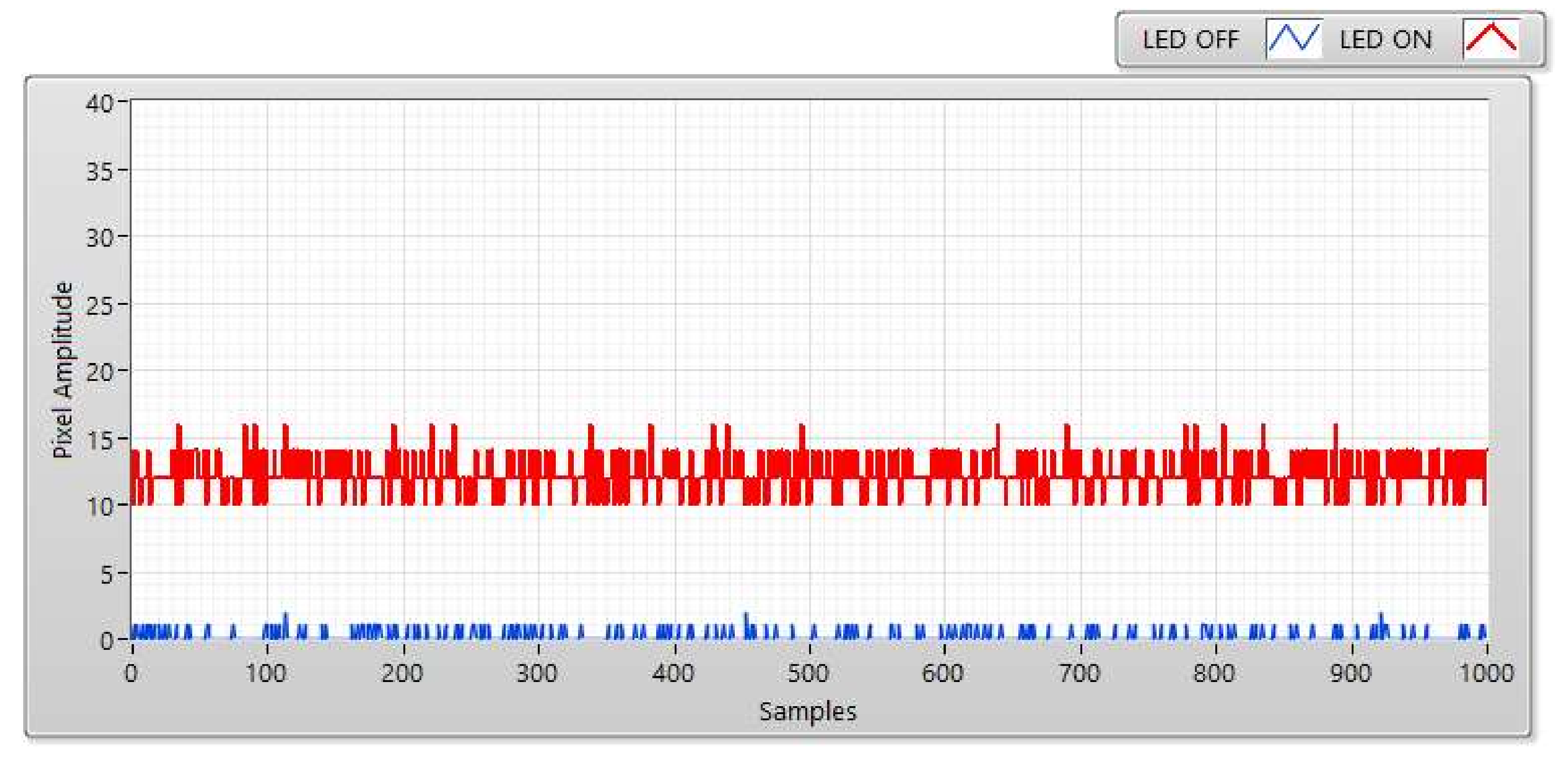
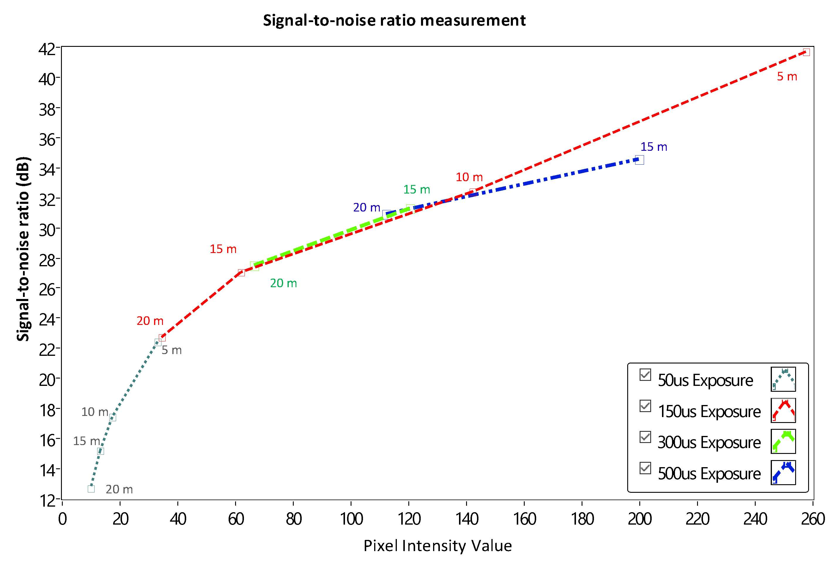
4.1. Experimental SNR Measurement
4.2. Simulation BER of COOK Scheme
4.3. Proposed Scheme
4.3.1. Oversampling
4.3.2. Undersampling
4.3.3. Maximum Length of Sub-Packet
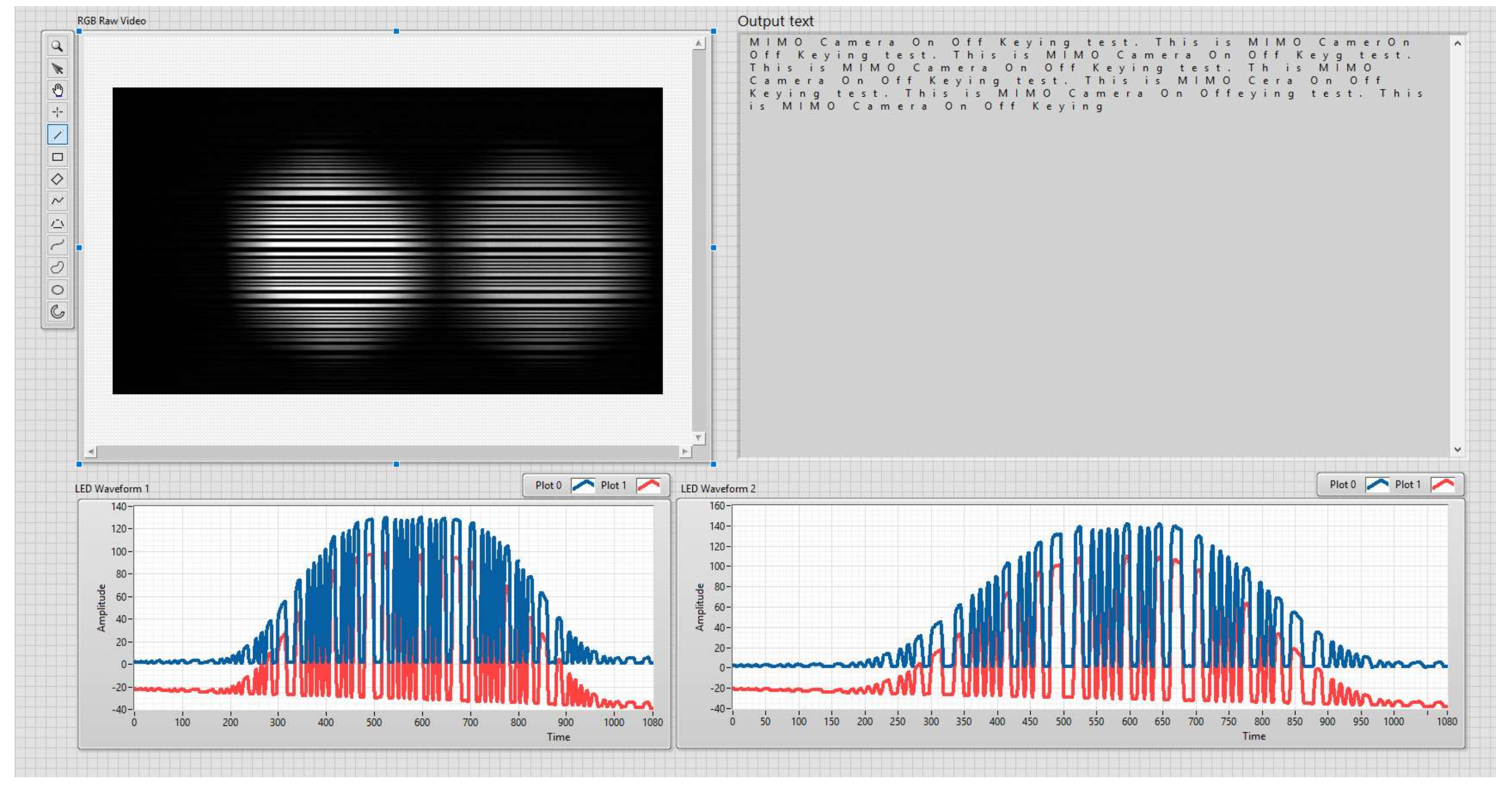
4.4. Implementation Results
5. Conclusions
Supplementary Materials
Author Contributions
Funding
Acknowledgments
Conflicts of Interest
References
- Kim, J.H.; Lee, J.K.; Kim, H.G.; Kim, K.B.; Kim, H.R. Possible Effects of Radiofrequency Electromagnetic Field Exposure on Central Nerve System. Biomol. Ther. 2019, 27, 265–275. [Google Scholar] [CrossRef] [PubMed]
- Haas, H.; Yin, L.; Chen, C.; Videv, S.; Parol, D.; Poves, E.; Alshaer, H.; Islim, M.S. Introduction to indoor networking concepts and challenges in LiFi. J. Opt. Commun. Netw. 2020, 12, A190–A203. [Google Scholar] [CrossRef]
- Chowdhury, M.Z.; Hossan, M.T.; Islam, A.; Jang, Y.M. A Comparative Survey of Optical Wireless Technologies: Architectures and Applications. IEEE Access 2018, 6, 9819–9840. [Google Scholar] [CrossRef]
- Haas, H. LiFi is paradigm-shifting 5G technology. Rev. Phys. 2018, 3, 26–31. [Google Scholar] [CrossRef]
- Rajagopal, S.; Roberts, R.D.; Lim, S.K. IEEE 802.15.7 Visible Light Communication: Modulation and Dimming Support. IEEE Commun. Mag. 2012, 50, 72–82. [Google Scholar] [CrossRef]
- Nikola, S.; Volker, J.; Yeong Min, J.; John, L.Q. An Overview on High-Speed Optical Wireless/Light Communications. Available online: https://mentor.ieee.org/802.11/dcn/17/11-17-0962-02-00lc-an-overview-on-high-speed-optical-wireless-light-communications.pdf (accessed on 1 February 2019).
- IEEE—SA. IEEE Std 802.15.7–2011–IEEE Standard for Local and Metropolitan Area Networks-Part 15.7: Short-Range Wireless Optical Communication Using Visible Light; IEEE-SA: Piscataway, NJ, USA, 2011. [Google Scholar]
- Nguyen, T.; Islam, A.; Yamazato, T.; Jang, Y.M. Technical Issues on IEEE 802.15.7m Image Sensor Communication Standardization. IEEE Commun. Mag. 2018, 56, 213–218. [Google Scholar] [CrossRef]
- Tan, K.S.; Hinberg, I.; Wadhwani, J. Electromagnetic interference in medical devices: Health Canada’s past current perspectives and activities. In Proceedings of the International Symposium on Electromagnetic Compatibility, Montreal, QC, Canada, 13–17 August 2001; pp. 1283–1288. [Google Scholar]
- Masao, T.A.K.I.; Watanabe, S. Biological and health effects of exposure to electromagnetic field from mobile communications system. IATSS Res. 2001, 25, 40–50. [Google Scholar]
- Ong, Z.; Rachim, V.P.; Chung, W.Y. Novel Electromagnetic-Interference-Free Indoor Environment Monitoring System by Mobile Camera Image Sensor based VLC. IEEE Photonics J. 2017, 9, 1–11. [Google Scholar] [CrossRef]
- Haas, H.; Yin, L.; Wang, Y.; Chen, C. What is LiFi? J. Lightwave Technol. 2015, 34, 1533–1544. [Google Scholar] [CrossRef]
- Ali, A.Y.; Zhang, Z.; Zong, B. Pulse position and shape modulation for visible light communication system. In Proceedings of the International Conference on Electromagnetics in Advanced Applications (ICEAA), Palm Beach, FL, USA, 3–8 August 2014; pp. 546–549. [Google Scholar]
- Deng, P.; Kavehrad, M. Real-time software-defined single-carrier QAM MIMO visible light communication system. In Proceedings of the Integrated Communications Navigation and Surveillance (ICNS), Herndon, VA, USA, 19–21 April 2016; pp. 5A3-1–5A3-11. [Google Scholar]
- Cai, H.B.; Zhang, J.; Zhu, Y.J.; Zhang, J.K.; Yang, X. Optimal constellation design for Indoor MIMO visible light communications. IEEE Commun. Lett. 2016, 20, 264–267. [Google Scholar] [CrossRef]
- Nguyen, T.; Nam, T.L.; Jang, Y.M. Practical Design of Screen-to-Camera based Optical Camera Communication. In Proceedings of the 2015 International Conference on Information Networking (ICOIN), Siem Reap, Cambodia, 12–14 January 2015. [Google Scholar]
- Nguyen, T.; Islam, A.; Hossan, T.; Jang, Y.M. Current Status and Performance Analysis of optical camera communication Technologies for 5G Networks. IEEE Access 2017, 5, 4574–4594. [Google Scholar] [CrossRef]
- Ayyash, M.; Elgala, H.; Khreishah, A.; Jungnickel, V.; Little, T.; Shao, S.; Rahaim, M.; Schulz, D.; Hilt, J.; Freund, R. Coexistence of WiFi and LiFi Toward 5G: Concepts, Opportunities, and Challenges. IEEE Commun. Mag. 2016, 54, 64–71. [Google Scholar] [CrossRef]
- Nguyen, T.; Islam, A.; Jang, Y.M. Region of Interest Signaling Vehicular System using optical camera communication. IEEE Photonics J. 2017, 9, 1–20. [Google Scholar] [CrossRef]
- Nguyen, H.; Thieu, M.D.; Nguyen, T.; Jang, Y.M. Rolling OFDM for Image Sensor Based Optical Wireless Communication. IEEE Photonics J. 2019, 11, 1–17. [Google Scholar] [CrossRef]
- Nguyen, T.; Thieu, M.D.; Jang, Y.M. 2D-OFDM for optical camera communication: Principle and Implementation. IEEE Access 2019, 7, 29405–29424. [Google Scholar] [CrossRef]
- Nguyen, T.; Hossain, M.A.; Jang, Y.M. Design and Implementation of a Novel Compatible Encoding Scheme in the Time Domain for Image Sensor Communication. Sensors 2016, 16, 736. [Google Scholar] [CrossRef] [PubMed]
- Yang, Y.; Hao, J.; Luo, J. CeilingTalk: Lightweight Indoor Broadcast through LED-Camera Communication. IEEE Trans. Mob. Comput. 2017, 16, 3308–3319. [Google Scholar] [CrossRef]
- Luo, P.; Zhang, M.; Ghassemlooy, Z.; Zvanovec, S.; Feng, S.; Zhang, P. Undersampled-Based Modulation Schemes for Optical Camera Communications. J. Opt. Commun. Netw. 2020, 56, 204–212. [Google Scholar] [CrossRef]
- IEEE—SA. IEEE Std 802.15.7–2018–IEEE Standard for Local and Metropolitan Area Networks—Part 15.7: Short-Range Optical Wireless Communications; IEEE-SA: Piscataway, NJ, USA, 2018. [Google Scholar]
- Barua, B. Comparision the performance of Free-Space Optical Communication with OOK and BPSK Modulation under Atmospheric Turbulence. Int. J. Comput. Eng. Sci. 2011, 3, 4391–4399. [Google Scholar]
- Lin, H.; Si, J.; Abousleman, G.P. Region-of-interest detection and its application to image segmentation and compression. In Proceedings of the International Conference on Integration of Knowledge Intensive Multi-Agent Systems, Waltham, MA, USA, 30 April–3 May 2007. [Google Scholar]
- Nguyen, H.; Thieu, M.D.; Pham, T.L.; Nguyen, H.; Jang, Y.M. The Impact of Camera Parameters on Optical Camera Communication. In Proceedings of the 2019 International Conference on Artificial Intelligence in Information and Communication (ICAIIC), Okinawa, Japan, 11–13 February 2019. [Google Scholar]


| RLL Code | Proposed Preamble (SF) |
|---|---|
| Manchester | 011100 |
| 4B6B | 0011111000 |
| 8B10B | 0000111111111100000 |
| Transmitter Side | ||||
| Clock rate | 8 kHz | 10 kHz | ||
| RLL | Manchester | 4B6B | Manchester | 4B6B |
| FEC | RS (15,11) | |||
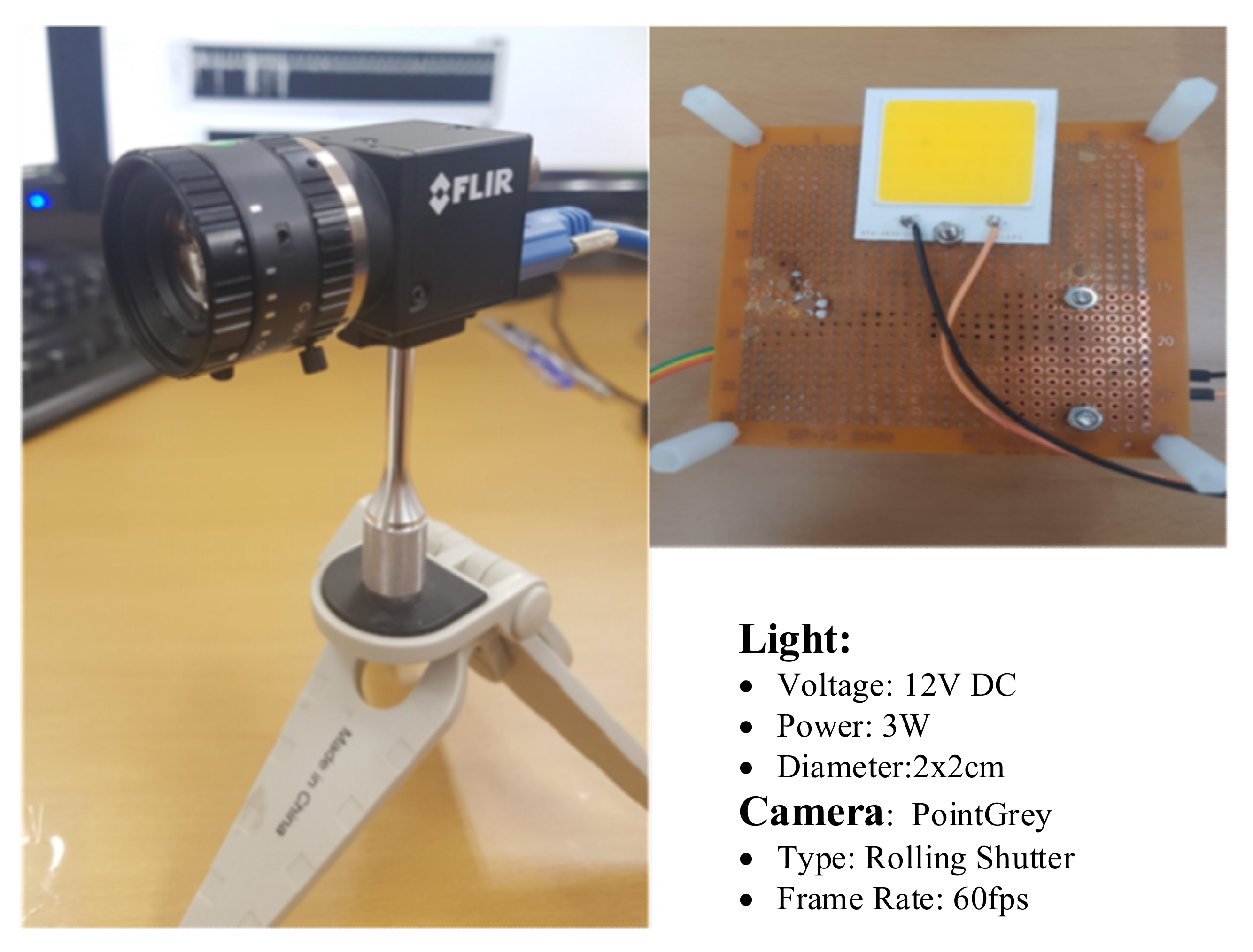
| LED type | 12 V, 3 W | |||
| Number of LEDs | 2 | |||
| Packet rate | 20 packet/s | |||
| Receiver side | ||||
| Camera | Point Gray rolling shutter camera | |||
| Camera frame rate | 60 fps | |||
| Data rate | ||||
| Uncode bit rate | 1.2 kbps | 1.8 kbps | 1.5 kbps | 2.25 kbps |
| Code bit rate | 0.88 kbps | 1.32 kbps | 1.1 kbps | 1.65 kbps |
© 2020 by the authors. Licensee MDPI, Basel, Switzerland. This article is an open access article distributed under the terms and conditions of the Creative Commons Attribution (CC BY) license (http://creativecommons.org/licenses/by/4.0/).
Share and Cite
Nguyen, V.H.; Thieu, M.D.; Nguyen, H.; Jang, Y.M. Design and Implementation of the MIMO–COOK Scheme Using an Image Sensor for Long-Range Communication. Sensors 2020, 20, 2258. https://doi.org/10.3390/s20082258
Nguyen VH, Thieu MD, Nguyen H, Jang YM. Design and Implementation of the MIMO–COOK Scheme Using an Image Sensor for Long-Range Communication. Sensors. 2020; 20(8):2258. https://doi.org/10.3390/s20082258
Chicago/Turabian StyleNguyen, Van Hoa, Minh Duc Thieu, Huy Nguyen, and Yeong Min Jang. 2020. "Design and Implementation of the MIMO–COOK Scheme Using an Image Sensor for Long-Range Communication" Sensors 20, no. 8: 2258. https://doi.org/10.3390/s20082258
APA StyleNguyen, V. H., Thieu, M. D., Nguyen, H., & Jang, Y. M. (2020). Design and Implementation of the MIMO–COOK Scheme Using an Image Sensor for Long-Range Communication. Sensors, 20(8), 2258. https://doi.org/10.3390/s20082258