Embedded Bio-Mimetic System for Functional Electrical Stimulation Controlled by Event-Driven sEMG †


Abstract
1. Introduction
2. System Architecture: Design and Development
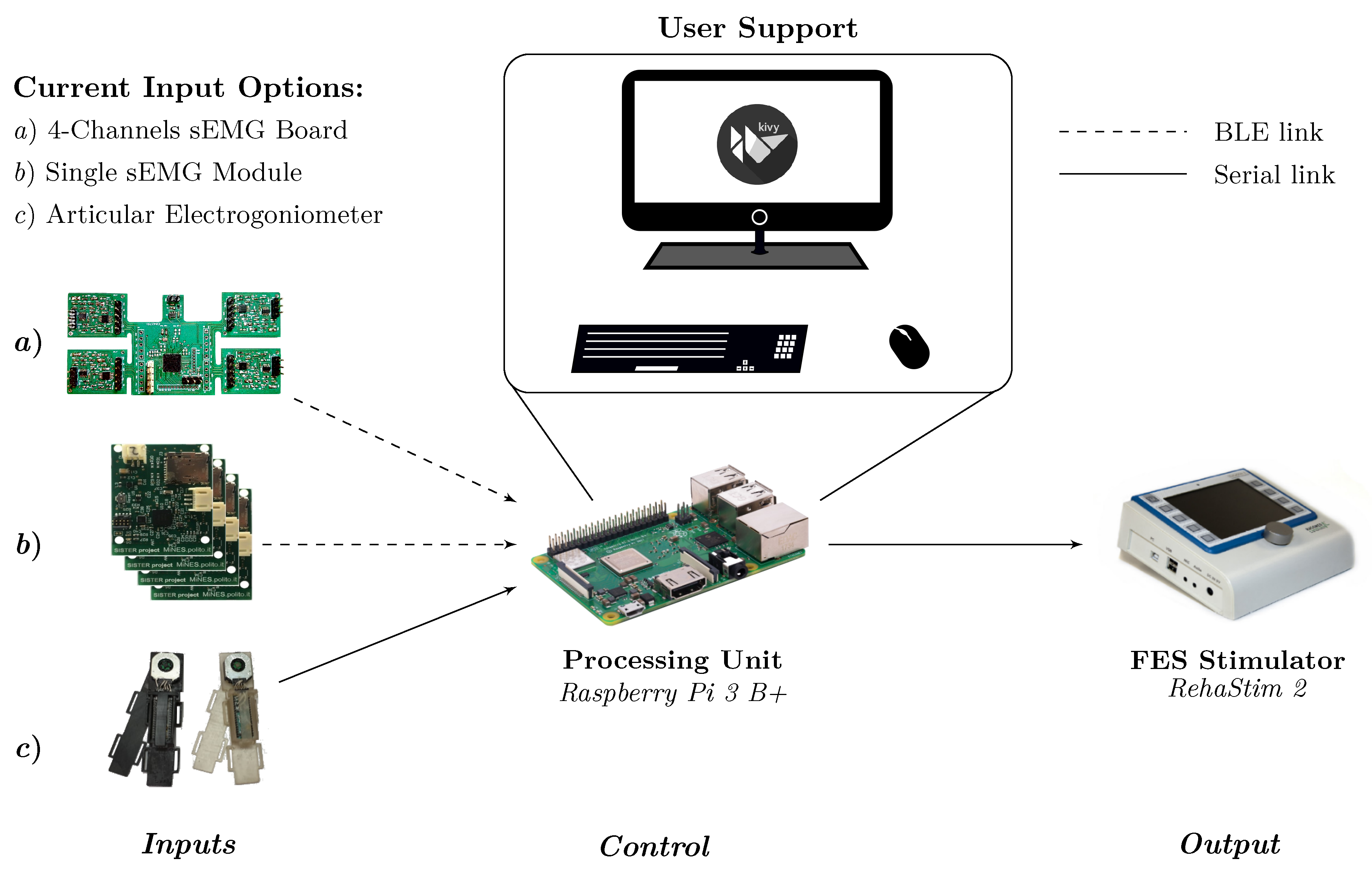
2.1. Overview
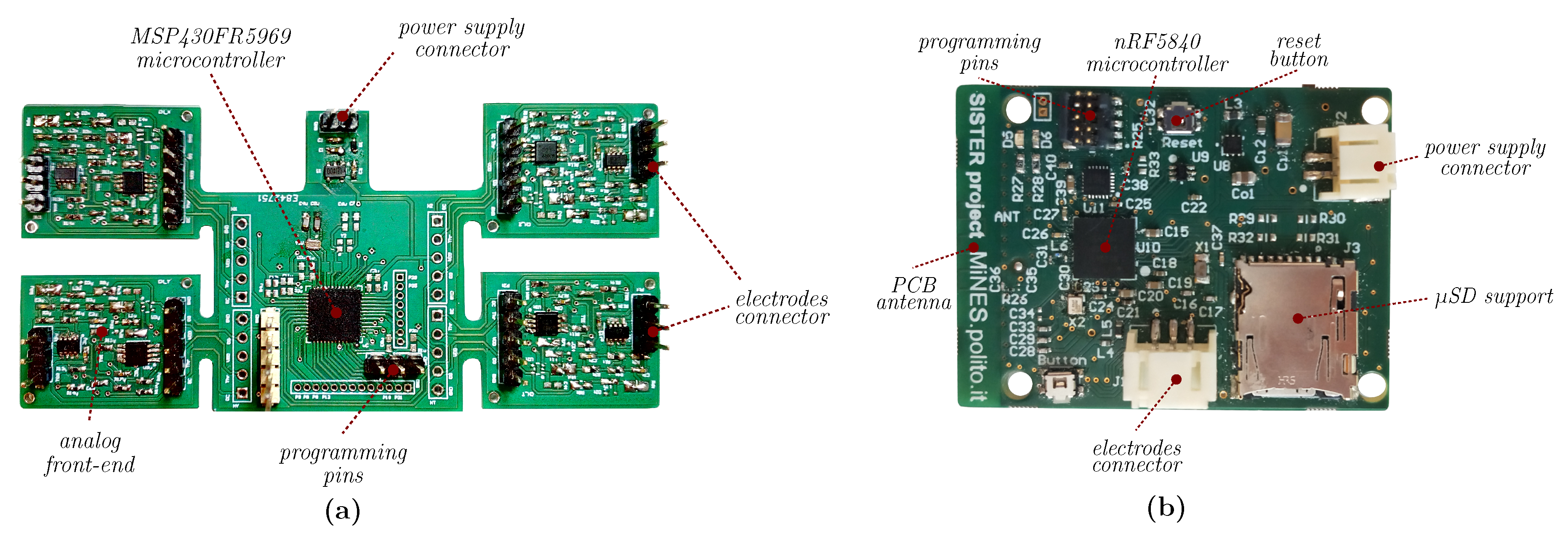
2.2. Hardware Platform
2.3. Software Overview
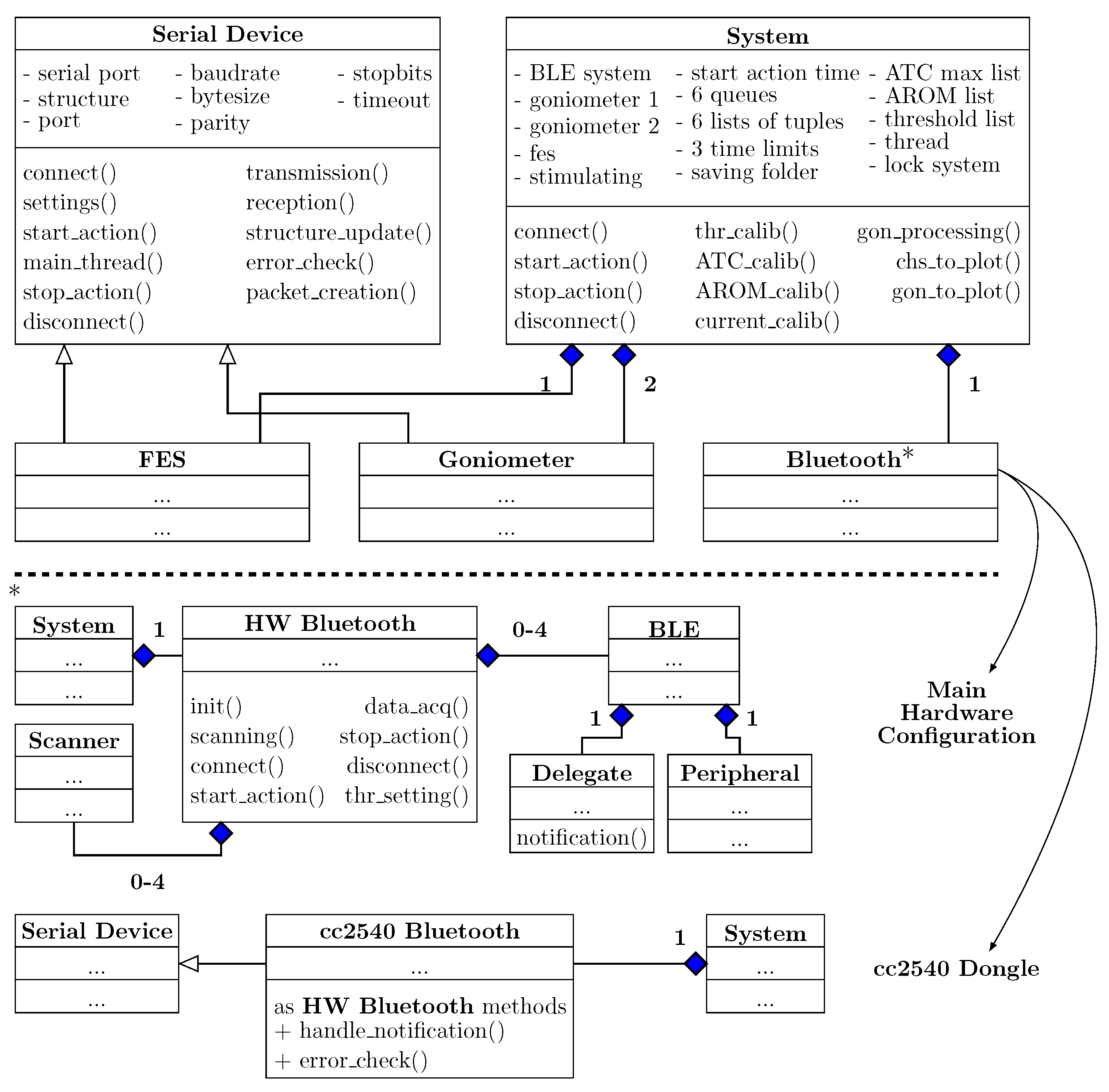
2.3.1. Classes Diagram Overview
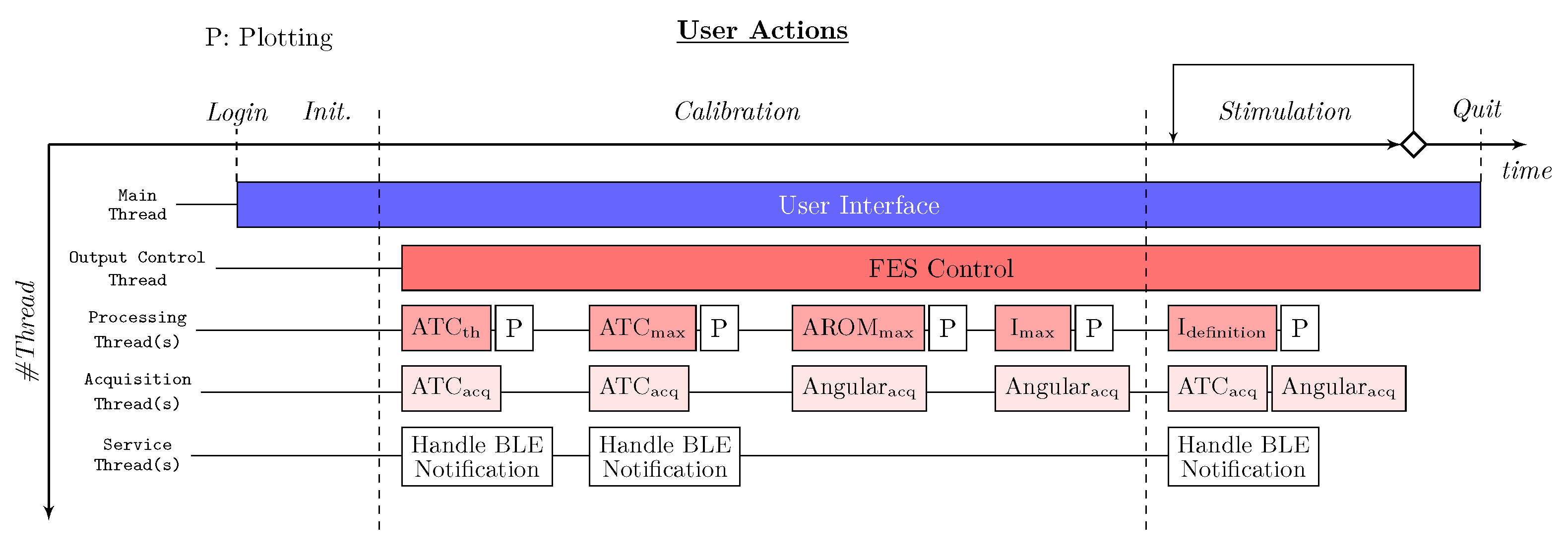
2.3.2. Multi-Threading
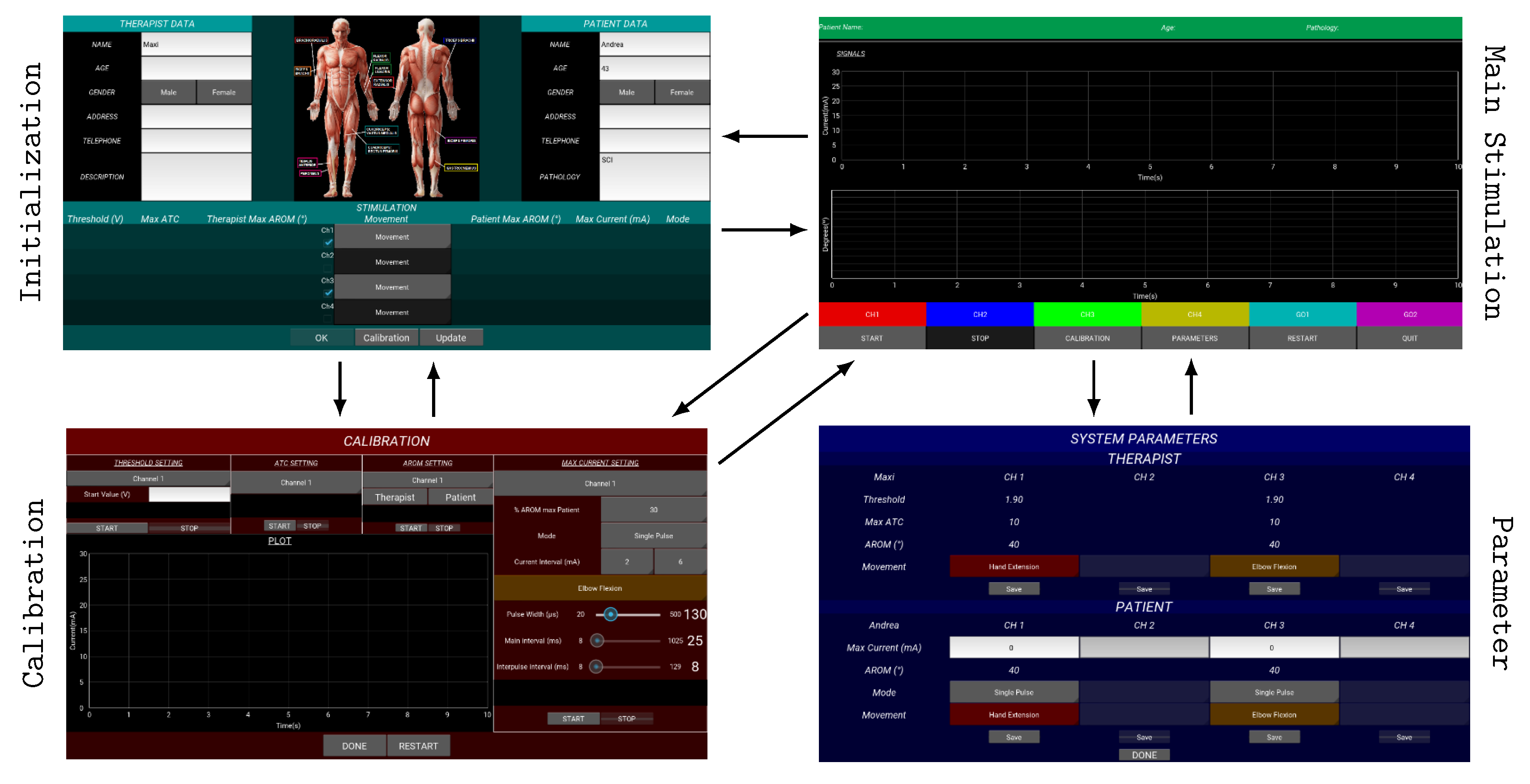
2.3.3. Graphical User Interface
2.4. ATC Dataflow: Processing and Calibration
- Threshold setting: The generation of the TC events strongly depends on the threshold value. Therefore, we tried to optimized the TCs setting the threshold just above the sEMG signal baseline in order to maximize the events with the minimal muscle effort. To accomplish this task, the therapist has to maintain a rest limb condition and, starting from an initial threshold value, we decrease it step-by-step until we find the baseline. Final threshold is set 30 above baseline reflecting voltage hysteresis comparator behavior.
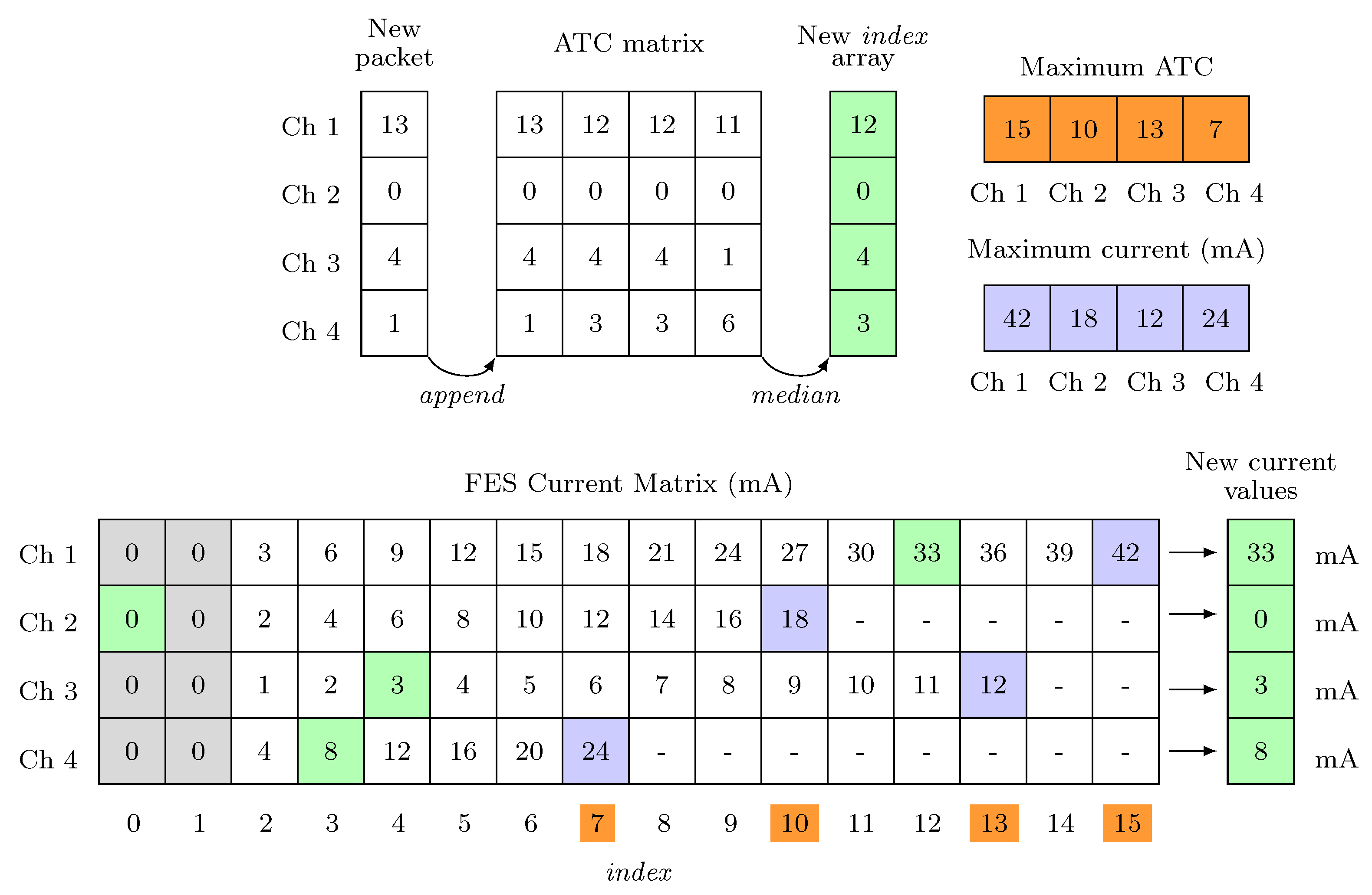
- Maximal ATC: The therapist has to repeat the movement to be calibrated at least four times. The maximal ATC value produced by the subject is calculated as the median value among the maximum of each repetition. This value limits the index dimension of the array, related to the calibrated channel, inside the FES Current Matrix, highlighted in orange in Figure 8.
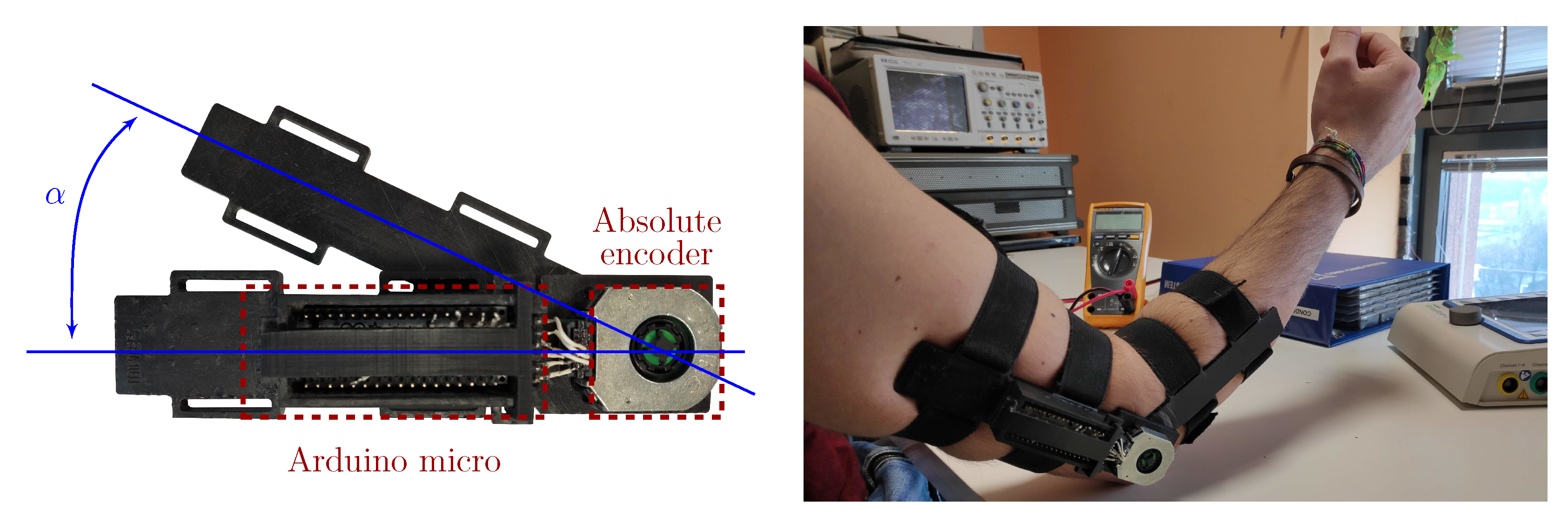
- AROM evaluation (optional): The maximal Absolute Range of Motion (AROM) of the involved articulation has been computed by processing the angular data of both therapist and patient. This measure standardizes the FES application and provides a comparison feedback between the voluntary movement and the stimulated one. We defined it as an optional step since the use of the electro-goniometers is not mandatory.
- Current limitation: We define the maximal current, useful to properly reproduce the movement, as the 110% of the current able to produce a 30% AROM variation in the stimulated subject. If the goniometer is not used, this step can be visually performed. Maximal Current values, represented in blue in Figure 8, related to the indexes defined by the Maximal ATC, define the proper stimulation values inter-step.
3. System Validation and Characterization
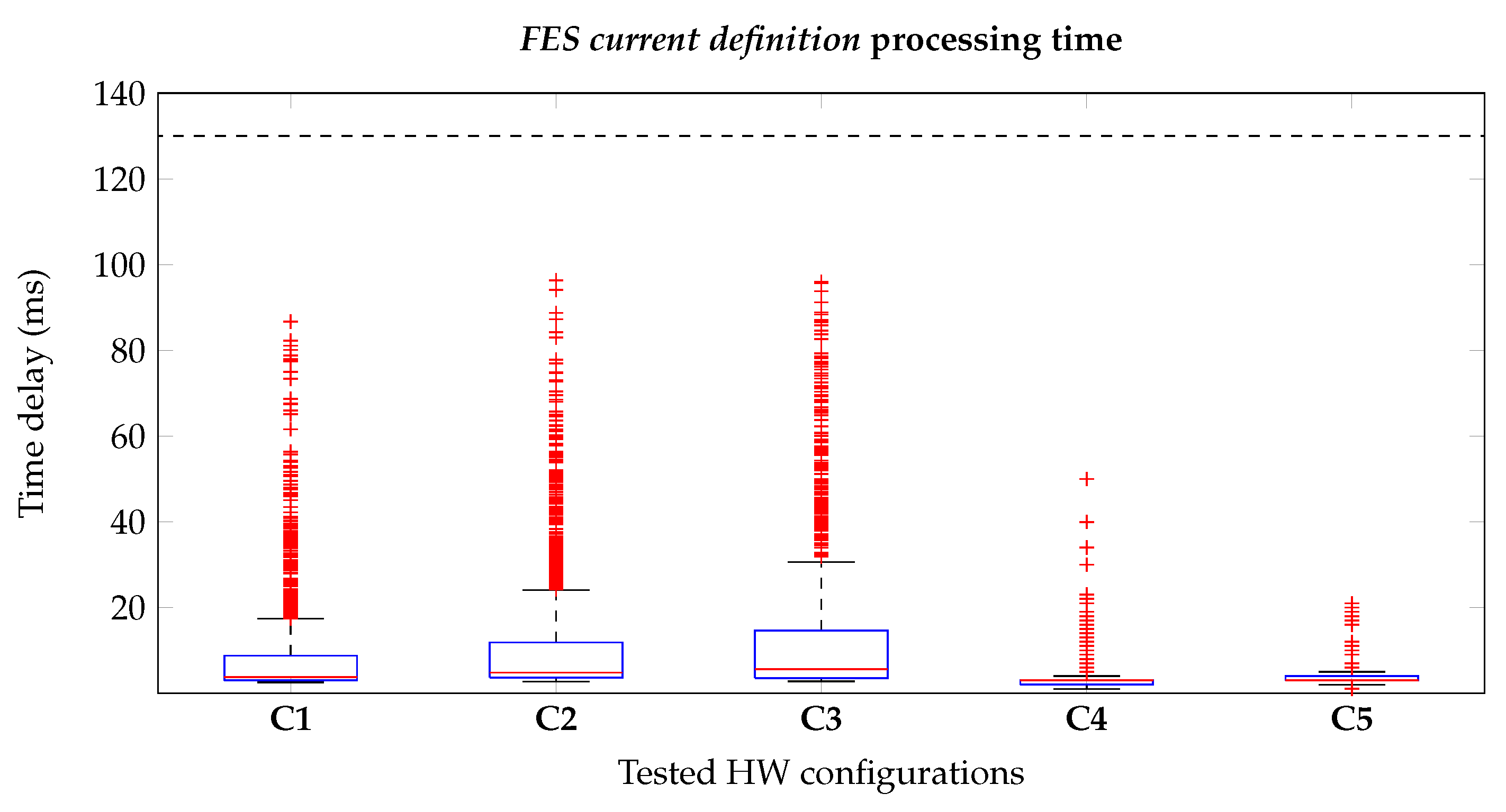
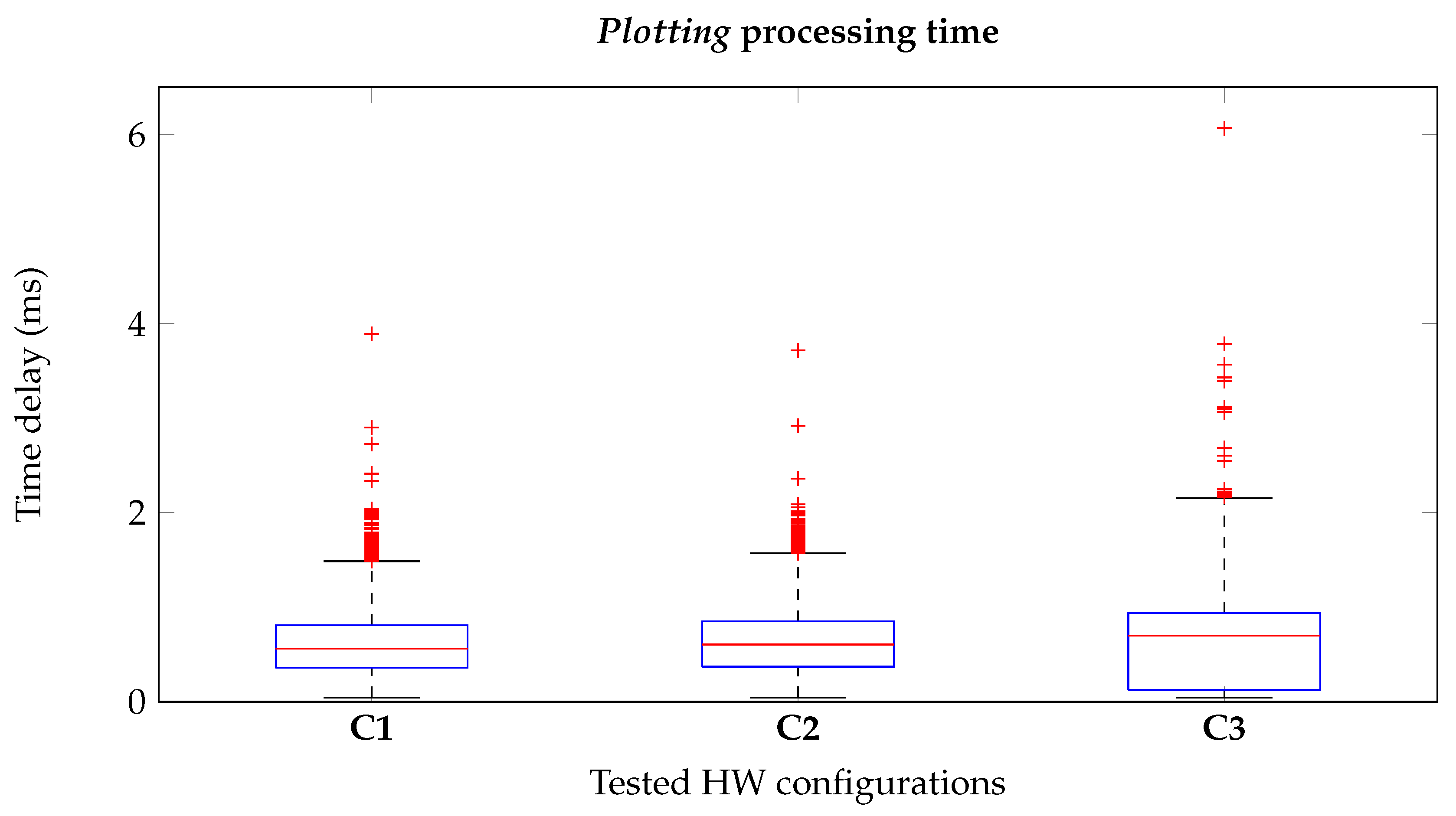
3.1. Latency Measurement
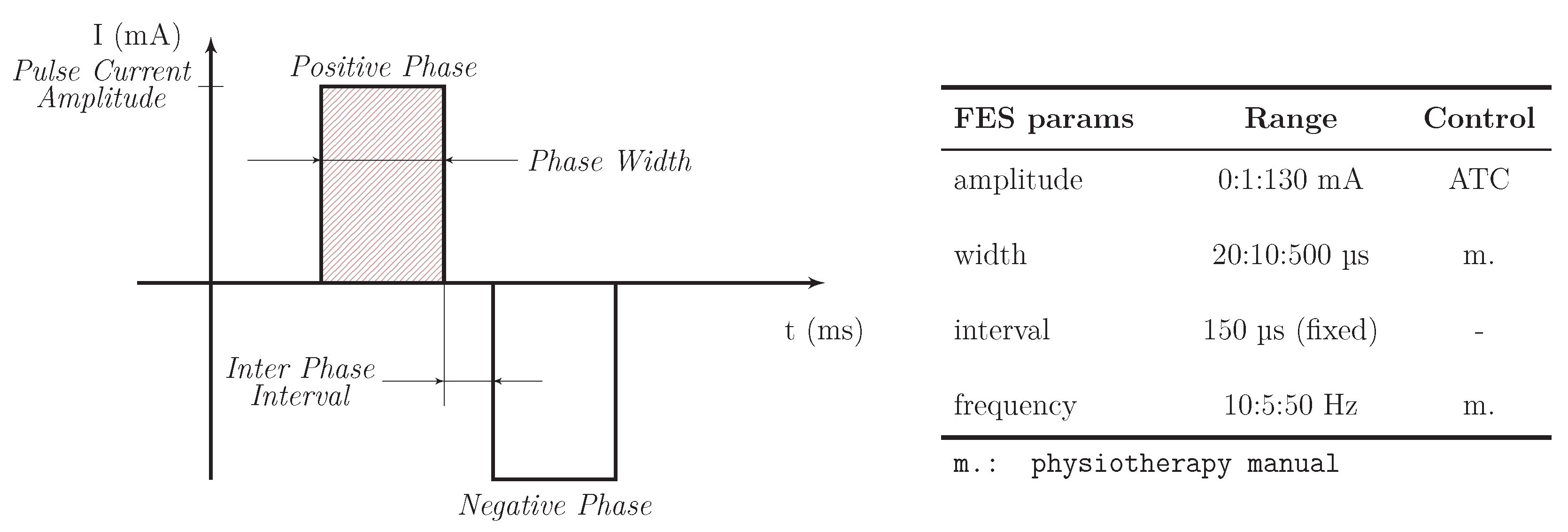
3.1.1. FES Current Definition
3.1.2. Plotting
3.2. Computational Performance
4. In Vivo Experimental Tests and Results
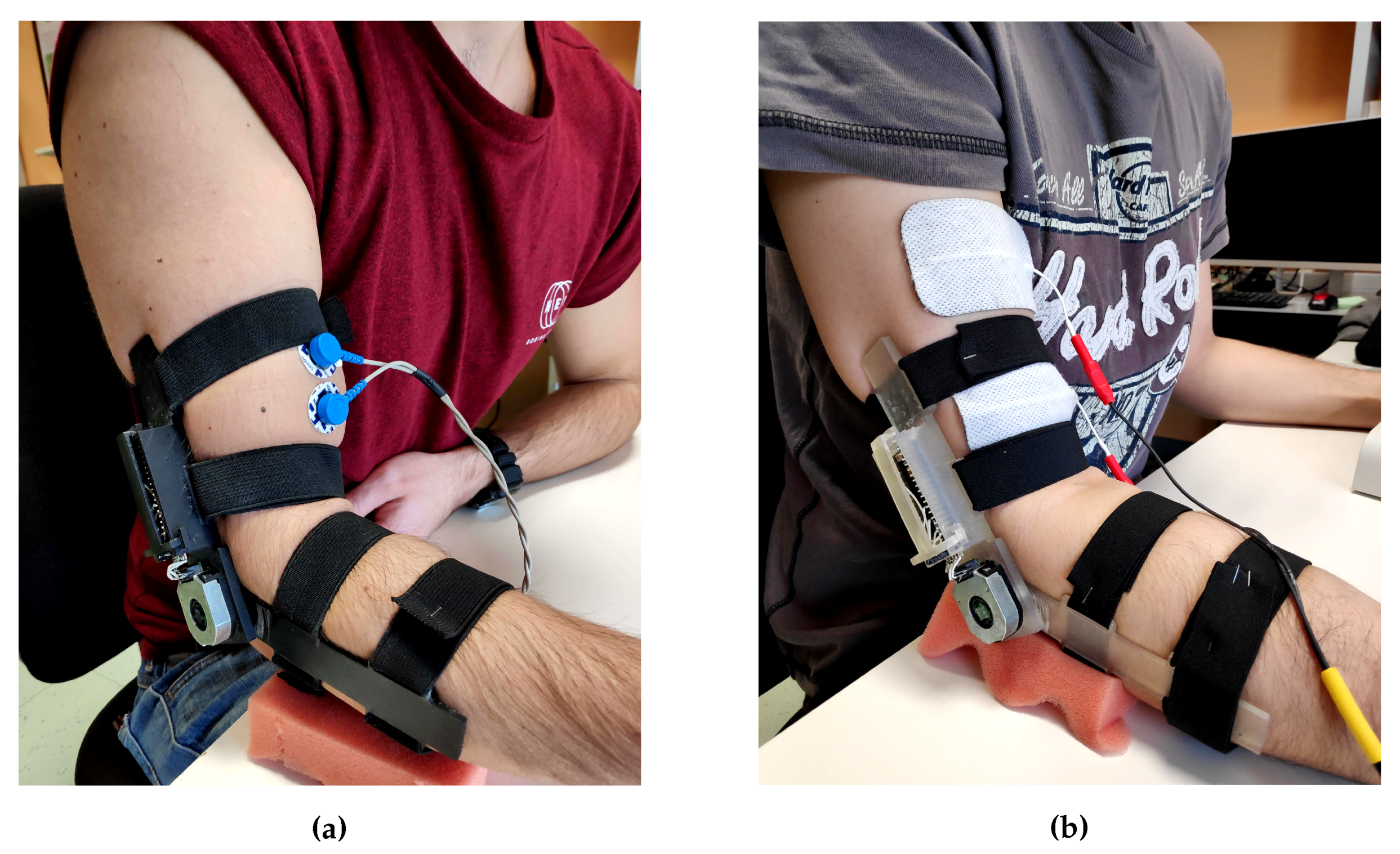
4.1. Electrodes and Skin Preparation
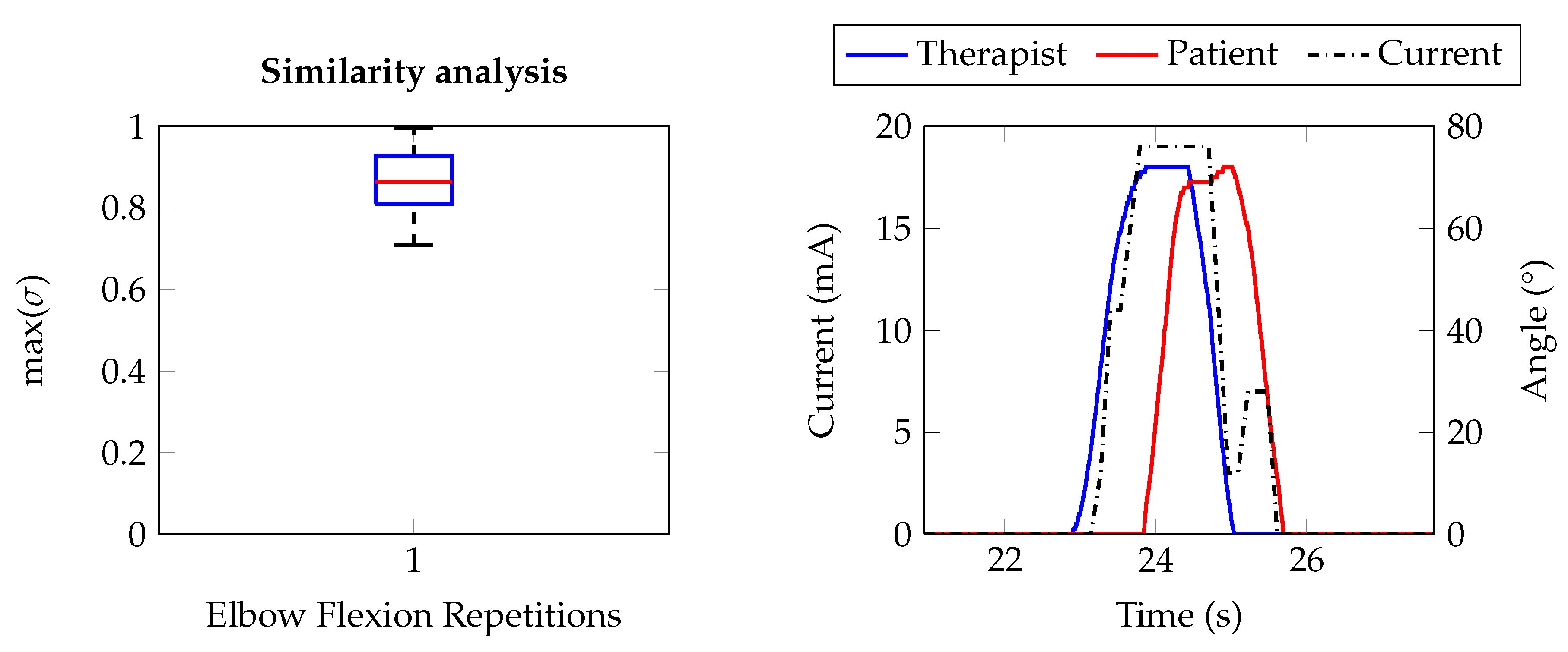
4.2. Upper Limb: Elbow Flexion
- Segmentation of the complete signals into single epochs representing one repetition.
- Baseline removal, since it could be different depending on the limb starting position.
- Signals normalization to the related AROM values.
- Computing of the maximum of the cross-correlation coefficient for each epoch.
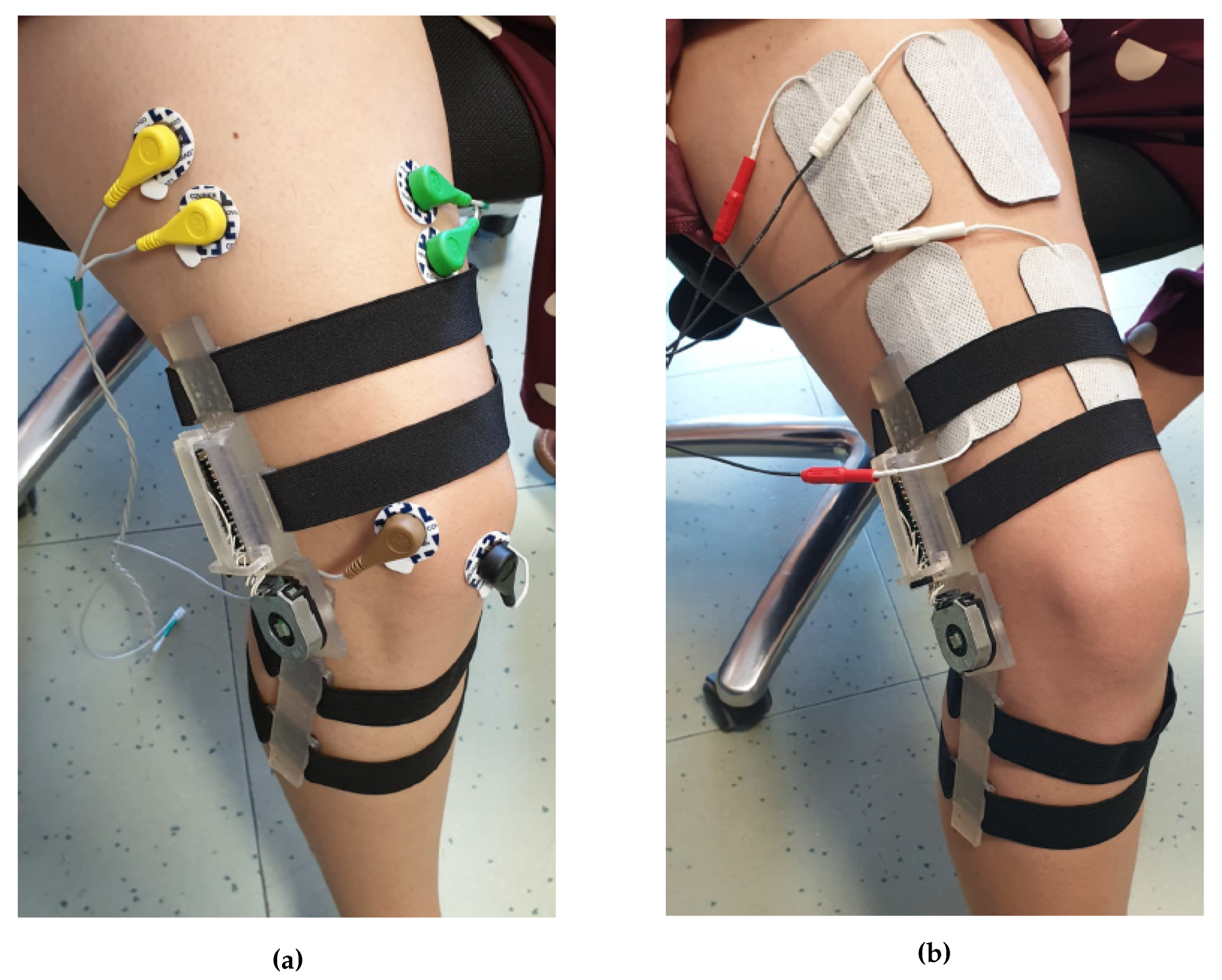
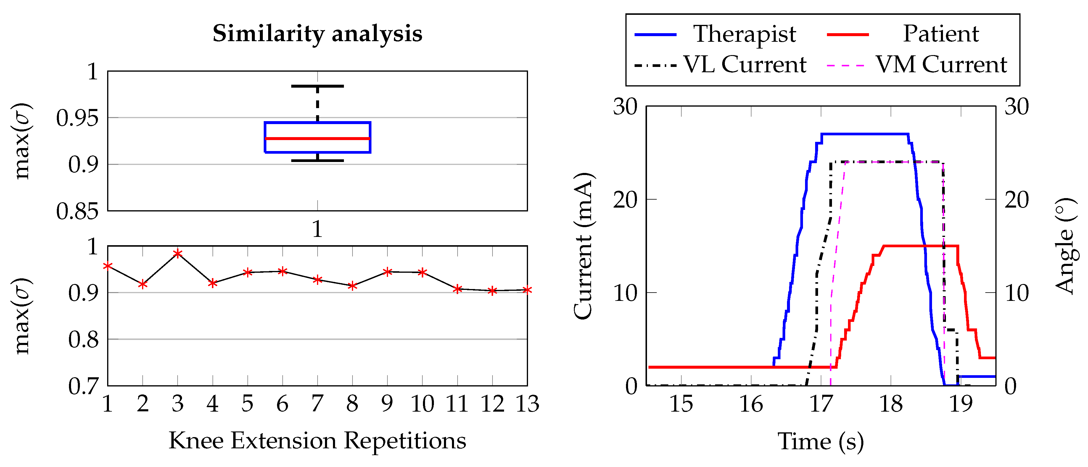
4.3. Lower Limb: Knee Extension
5. Discussion: sEMG-FES Systems Comparison
6. Conclusion and Future Perspectives
Author Contributions
Funding
Acknowledgments
Conflicts of Interest
References
- Ferrante, S.; Chia Bejarano, N.; Ambrosini, E.; Nardone, A.; Turcato, A.M.; Monticone, M.; Ferrigno, G.; Pedrocchi, A. A Personalized Multi-Channel FES Controller Based on Muscle Synergies to Support Gait Rehabilitation after Stroke. Front. Neurosci. 2016, 10, 425. [Google Scholar] [CrossRef] [PubMed]
- Perruchoud, D.; Pisotta, I.; Carda, S.; Murray, M.M.; Ionta, S. Biomimetic Rehabilitation Engineering: The Importance of Somatosensory Feedback for Brain–Machine Interfaces. J. Neural Eng. 2016, 13, 041001. [Google Scholar] [CrossRef] [PubMed]
- Reilly, J.P. Electrical Stimulation and Electropathology. In Electrical Stimulation and Electropathology, 1st ed.; Press, C.U., Ed.; Press Syndicate of the University of Cambridge: Cambridge, UK, 1992; Chapter 8: Skeletal Muscle Response to Electrical Stimulation by Sweeney, J. D. [Google Scholar]
- Toledo, C.; Martinez, J.; Mercado, J.; Isabel Martín-Vignon-Whaley, A.; Vera-Hernández, A.; Leija-Salas, L. sEMG Signal Acquisition Strategy towards Hand FES Control. J. Healthcare Eng. 2018, 2018, 1–11. [Google Scholar] [CrossRef] [PubMed]
- Li, Z.; Guiraud, D.; Andreu, D.; Benoussaad, M.; Fattal, C.; Hayashibe, M. Real-time Estimation of FES-induced Joint Torque with Evoked EMG. J. NeuroEng. Rehabil. 2016, 13, 60. [Google Scholar] [CrossRef] [PubMed]
- Shahshahani, A.; Shahshahani, M.; Motto Ros, P.; Bonanno, A.; Crepaldi, M.; Martina, M.; Demarchi, D.; Masera, G. An all-digital spike-based ultra-low-power IR-UWB dynamic average threshold crossing scheme for muscle force wireless transmission. In Proceedings of the 2015 Design, Automation & Test in Europe Conference & Exhibition (DATE), Grenoble, France, 9–13 March 2015; pp. 1479–1484. [Google Scholar]
- Crepaldi, M.; Paleari, M.; Bonanno, A.; Sanginario, A.; Ariano, P.; Tran, D.H.; Demarchi, D. A quasi-digital radio system for muscle force transmission based on event-driven IR-UWB. In Proceedings of the 2012 IEEE Biomedical Circuits and Systems Conference (BioCAS), Hsinchu, Taiwan, 28–30 November 2012; pp. 116–119. [Google Scholar] [CrossRef]
- Sapienza, S.; Crepaldi, M.; Motto Ros, P.; Bonanno, A.; Demarchi, D. On Integration and Validation of a Very Low Complexity ATC UWB System for Muscle Force Transmission. In Proceedings of the IEEE Transactions on Biomedical Circuits and Systems, Paphos, Cyprus, 31 March–2 April 2016; Volume 10, pp. 497–506. [Google Scholar] [CrossRef]
- Guzman, D.; Sapienza, S.; Sereni, B.; Motto Ros, P. Very Low Power Event-Based Surface EMG Acquisition System with Off-the-Shelf Components. In Proceedings of the 2017 IEEE Biomedical Circuits and Systems Conference (BioCAS), Turin, Italy, 19–21 October 2017. [Google Scholar]
- Rossi, F.; Motto Ros, P.; Sapienza, S.; Bonato, P.; Bizzi, E.; Demarchi, D. Wireless Low Energy System Architecture for Event-Driven Surface Electromyography. In ApplePies 2018: Applications in Electronics Pervading Industry, Environment and Society; Springer: New York, NY, USA, 2019; pp. 179–185. [Google Scholar] [CrossRef]
- Motto Ros, P.; Paleari, M.; Celadon, N.; Sanginario, A.; Bonanno, A.; Crepaldi, M.; Ariano, P.; Demarchi, D. A wireless address-event representation system for ATC-based multi-channel force wireless transmission. In Proceedings of the 5th IEEE International Workshop on Advances in Sensors and Interfaces IWASI, Bari, Italy, 13–14 June 2013; pp. 51–56. [Google Scholar] [CrossRef]
- Sapienza, S.; Motto Ros, P.; Fernandez Guzman, D.A.; Rossi, F.; Terracciano, R.; Cordedda, E.; Demarchi, D. On-Line Event-Driven Hand Gesture Recognition Based on Surface Electromyographic Signals. In Proceedings of the 2018 IEEE International Symposium on Circuits and Systems (ISCAS), Florence, Italy, 27–30 May 2018; pp. 1–5. [Google Scholar]
- Mongardi, A.; Rossi, F.; Motto Ros, P.; Sanginario, A.; Ruo Roch, M.; Martina, M.; Demarchi, D. Live Demonstration: Low Power Embedded System for Event-Driven Hand Gesture Recognition. In Proceedings of the 2019 IEEE Biomedical Circuits and Systems Conference (BioCAS), Nara, Japan, 17–19 October 2019. [Google Scholar]
- Mongardi, A.; Motto Ros, P.; Rossi, F.; Ruo Roch, M.; Martina, M.; Demarchi, D. A Low-Power Embedded System for Real-Time sEMG based Event-Driven Gesture Recognition. In Proceedings of the 2019 26th IEEE International Conference on Electronics, Circuits and Systems (ICECS), Genova, Italy, 27–29 November 2019; pp. 65–68. [Google Scholar]
- Barioul, R.; Fakhfakh, S.; Derbel, H.; Kanoun, O. Evaluation of EMG Signal Time Domain Features for Hand Gesture Distinction. In Proceedings of the 2019 16th International Multi-Conference on Systems, Signals Devices (SSD), Istanbul, Turkey, 21–24 March 2019; pp. 489–493. [Google Scholar]
- Toledo-Pérez, D.C.; Rodríguez-Reséndiz, J.; Gómez-Loenzo, R.A. A Study of Computing Zero Crossing Methods and an Improved Proposal for EMG Signals. IEEE Access 2020, 8, 8783–8790. [Google Scholar] [CrossRef]
- Rossi, F.; Motto Ros, P.; Demarchi, D. Live Demonstration: Low Power System for Event-Driven Control of Functional Electrical Stimulation. In Proceedings of the 2018 IEEE International Symposium on Circuits and Systems (ISCAS), Florence, Italy, 27–30 May 2018; p. 1. [Google Scholar]
- Rossi, F.; Motto Ros, P.; Cecchini, S.; Crema, A.; Micera, S.; Demarchi, D. An Event-Driven Closed-Loop System for Real-Time FES Control. In Proceedings of the 2019 26th IEEE International Conference on Electronics, Circuits and Systems (ICECS), Genova, Italy, 27–29 November 2019; pp. 867–870. [Google Scholar]
- Rossi, F.; Rosales, M.R.; Motto Ros, P.; Demarchi, D. Real-Time Embedded System for Event-Driven sEMG Acquisition and Functional Electrical Stimulation Control. In Proceedings of the 2019 International Conference on Application in Electronics Pervading Industry, Environment and Society, Pisa, Italy, 11–13 September 2019. [Google Scholar]
- De Luca, C.J. Surface Electromyography: Detection and Recording; DelSys Incorporated: Natick, MA, USA, 2002. [Google Scholar]
- De Luca, G. Fundamental Concepts in EMG Signal Acquisition; DelSys Incorporated: Natick, MA, USA, 2001. [Google Scholar]
- Spinelli, E.M.; Pallas-Areny, R.; Mayosky, M.A. AC-coupled front-end for biopotential measurements. IEEE Trans. Biomed. Eng. 2003, 50, 391–395. [Google Scholar] [CrossRef] [PubMed]
- Franco, S. Design with Operational Amplifiers and Analog Integrated Circuits; Mac Graw Hill: New York, NY, USA, 2002. [Google Scholar]
- (SIG), B.S.I.G. BLUETOOTH SPECIFICATION Version 4.1 - Specification of the Bluetooth® System. Available online: https://www.microchip.com/ (accessed on 3 December 2013).
- Microchip. RN4020 Bluetooth Low Energy Module DataSheet. 2015, pp. 1–28. Available online: https://www.microchip.com/ (accessed on 3 December 2013).
- Semiconductor, N. nRF52840 Dongle. Available online: https://www.nordicsemi.com/Software-and-tools/Development-Kits/nRF52840-Dongle (accessed on 9 March 2020).
- Devices, C. AMT20 Series Datasheet - Modular | Absolute | CUI Devices. 2019, pp. 1–10. Available online: https://www.cuidevices.com/ (accessed on 21 December 2019).
- Arduino Micro. Available online: https://store.arduino.cc/arduino-micro (accessed on 9 March 2020).
- Jessop, D.; Pain, M. Maximum Velocities in Flexion and Extension Actions for Sport. J. Human Kinet. 2016, 50. [Google Scholar] [CrossRef] [PubMed][Green Version]
- Formlabs. Available online: https://formlabs.com/it/3d-printers/form-2/ (accessed on 9 March 2020).
- GmbH, H. Operation Manual RehaStim 2, RehaMove 2 - User Guide. Available online: https://hasomed.de/ (accessed on 21 November 2012).
- Kuberski, B. ScienceMode2 - Description and Protocol. Available online: https://hasomed.de/ (accessed on 12 December 2012).
- Popovic, M.; Masani, K.; Micera, S. Functional Electrical Stimulation Therapy: Recovery of Function Following Spinal Cord Injury and Stroke. In Neurorehabilitation Technology; Springer: Cham, Switzerland, 2016. [Google Scholar]
- GmbH, H. RehaMove Functional Electrical Stimulation—FES Applications. 2015. Available online: https://hasomed.de/ (accessed on 9 March 2020).
- Foundation, R.P. Raspberry Pi 3 B+ Specifications. Available online: https://www.raspberrypi.org/products/raspberry-pi-3-model-b-plus/ (accessed on 9 March 2020).
- Instruments, T. CC2540 Bluetooth Low Energy USB Dongle, 5 May 2015. Available online: http://www.ti.com/lit/ug/tidu977/tidu977.pdf (accessed on 9 March 2020).
- Kivy. Kivy Home. Available online: https://kivy.org/#home (accessed on 9 March 2020).
- Philips, D. Python 3 Object-oriented Programming, 2nd ed.; Packt Publishing: Birmingham, UK, 2015. [Google Scholar]
- Lott, S. Functional Python Programming; Packt Publishing: Birmingham, UK, 2015. [Google Scholar]
- BlueZ. BlueZ: Official Linux Bluetooth protocol stack. Available online: http://www.bluez.org/about/ (accessed on 9 March 2020).
- Harvey, I. Bluepy: Python interface to Bluetooth LE on Linux. Available online: https://github.com/IanHarvey/bluepy (accessed on 9 March 2020).
- Ulloa, R. Kivy - Interactive Applications and Games in Python, 2nd ed; Puckt Publishing: Birmingham, UK, 2015. [Google Scholar]
- Stegeman, D.; Hermens, H. Standards for Suface Electromyography: The European Project Surface EMG for Non-Invasive Assessment of Muscles (SENIAM). 2007. Available online: https://www.researchgate.net/publication/228486725_Standards_for_suface_electromyography_The_European_project_Surface_EMG_for_non-invasive_assessment_of_muscles_SENIAM (accessed on 9 March 2020).
- Covidien. Kendall™ ECG Electrodes Product Data Sheet - Arbo™ H124SG. Available online: https://www.medtronic.com/ (accessed on 9 March 2020).
- FES STANDARD (5CM X 9CM) REHATRODE ELECTRODES. Available online: https://www.fescycling.com/shop/fes-rehatrode-electrodes-standard (accessed on 9 March 2020).
- Kleiber, T.; Kunz, L.; Disselhorst-Klug, C. Muscular coordination of biceps brachii and brachioradialis in elbow flexion with respect to hand position. Front. Physiol. 2015, 6, 215. [Google Scholar] [CrossRef] [PubMed]
- LTD, A.M.C. Education: Electrode Placement. Available online: https://www.axelgaard.com/Education/Elbow-Flexion (accessed on 9 March 2020).
- Bordoni, B.; Varacallo, M. Anatomy, Bony Pelvis and Lower Limb, Thigh Quadriceps Muscle. Available online: https://www.axelgaard.com/Education/Elbow-Flexion (accessed on 9 March 2020).
- Zhou, Y.; Fang, Y.; Zeng, J.; Li, K.; Liu, H. A Multi-channel EMG-Driven FES Solution for Stroke Rehabilitation. In Proceedings of the 11th International Conference Intelligent Robotics and Applications (ICIRA), Newcastle, NSW, Australia, 9–11 August 2018; pp. 235–243. [Google Scholar] [CrossRef]
- Fang, Y.; Chen, S.; Wang, X.; Leung, K.W.C.; Wang, X.; Tong, K. Real-time Electromyography-driven Functional Electrical Stimulation Cycling System for Chronic Stroke Rehabilitation. In Proceedings of the 2018 40th Annual International Conference of the IEEE Engineering in Medicine and Biology Society (EMBC), Honolulu, HI, USA, 18–21 July 2018; pp. 2515–2518. [Google Scholar] [CrossRef]
- Wang, H.P.; Bi, Z.Y.; Zhou, Y.; Zhou, Y.; Wang, Z.G.; Lv, X.Y. Real-time and wearable functional electrical stimulation system for volitional hand motor function control using the electromyography bridge method. Neural Regener. Res. 2017, 12, 133. [Google Scholar] [CrossRef]
- Shima, K.; Shimatani, K. A new approach to direct rehabilitation based on functional electrical stimulation and EMG classification. In Proceedings of the 2016 International Symposium on Micro-NanoMechatronics and Human Science (MHS), Nagoya, Japan, 28–30 November 2016; pp. 1–6. [Google Scholar] [CrossRef]
- Valtin, M.; Kociemba, K.; Behling, C.; Kuberski, B.; Becker, S.; Schauer, T. RehaMovePro: A versatile mobile stimulation system for transcutaneous FES applications. Eur. J. Transl. Myol. 2016, 26, 3. [Google Scholar] [CrossRef] [PubMed]
- Toledo Peral, C.L.; Nava, G.H.; Melía Licona, J.A.; Mercado Gutiérrez, J.A.; Aguirre Guemez, A.V.; Fresnedo, J.Q.; Hernández, A.V.; Salas, L.L.; Martínez, J.G. ON/OFF sEMG Switch for FES Activation. In Proceedings of the 2019 16th International Conference on Electrical Engineering, Computing Science and Automatic Control (CCE), Mexico City, Mexico, 11–13 September 2019; pp. 1–5. [Google Scholar] [CrossRef]
- Bi, Z.; Bao, X.; Wang, H.; Lv, X.; Wang, Z. Prototype System Design and Experimental Validation of Gait-Oriented EMG Bridge for Volitional Motion Function Rebuilding of Paralyzed Leg. In Proceedings of the 2019 IEEE 7th International Conference on Bioinformatics and Computational Biology ( ICBCB), Hangzhou, China, 21–23 March 2019; pp. 79–82. [Google Scholar] [CrossRef]


| Acquisition Device | Control Unit | BLE Module | |||
|---|---|---|---|---|---|
| Config. | Single Channel | 4-Channel Board | GNU/Linux Raspberry | Microsoft® Windows® PC | CC2540 * |
| C1 | ✓ | ✓ | |||
| C2 | ✓ | ✓ | ✓ | ||
| C3 | ✓ | ✓ | ✓ | ||
| C4 | ✓ | ✓ | ✓ | ||
| C5 | ✓ | ✓ | ✓ | ||
| Configuration | |||||
|---|---|---|---|---|---|
| Method | C1 | C2 | C3 | C4 | C5 |
| queue | 90.71% | 92.78% | 88.03% | 97.41% | 97.25% |
| append | 1.43% | 1.03% | 2.35% | - | - |
| median | 1.65% | 1.40% | 2.24% | 0.53% | 0.52% |
| FES_start | 5.11% | 3.81% | 6.04% | 1.57% | 1.63% |
| plot | 0.68% | 0.62% | 0.81% | - | - |
| 100% | 100% | 100% | 100% | 100% | |
| Configuration | |||||
|---|---|---|---|---|---|
| Method | C1 | C2 | C3 | C4 | C5 |
| get_value | 0.94% | 0.93% | 0.95% | 0.45% | 0.41% |
| sleep | 99.06% | 99.07% | 99.05% | 99.55% | 99.59% |
| 100% | 100% | 100% | 100% | 100% | |
| Stages | CPU (%) | RAM (MB) |
|---|---|---|
| Login | 20 | 84 |
| Initialization | 21 | 85 |
| Threshold calibration * | 24.1 | 88.9 |
| ATC maximum calibration * | 26 | 87 |
| AROM evaluation * | 32 | 89 |
| Maximum current calibration * | 45.7 | 89 |
| Stimulation | 73.2 | 87.8 |
| Parameters | 15 | 88.3 |
| 1 Ch. | 4 Ch. | 1 Ch. | 4 Ch. | ||
|---|---|---|---|---|---|
| Process | I/O operations | ✓ | ✓ | ✓ | ✓ |
| ATC processing | ✓ | ✓ | x | x | |
| Resources | CPU (%) | 53.8 | 73.2 | 53 | 74.4 |
| RAM (MB) | 87.7 | 87.8 | 91 | 92 |
| Work | Control Feature | FES Parameter | Processing HW | Embedded | Wireless | Modular System | #Ch | Latency (ms) |
|---|---|---|---|---|---|---|---|---|
| [49] | RMS | intensity | MCU | ✓ | Bluetooth | x | 8 | 300 |
| [50] | envelope | intensity | n.a. | x | x | n.a. | 4 | n.a. |
| [51] | threshold crossing | frequency | MCU | ✓ | 335/433 | x | 2 | 142 |
| [52] | force angle | intensity | PC | x | x | n.a. | 4 | n.a. |
| [53] | sEMG IMU | intensity width | MCU | ✓ | Bluetooth 2.1 | x | 4 | 21 |
| [54] | envelope | on/off stimuli | PC | x | x | x | 1 | 1600 |
| [55] | entropy | frequency width | MCU | ✓ | x | x | 1 | 300 1 |
| [10,18] | ATC | intensity | PC | x | Bluetooth 4.2 | ✓ | 4 | 774.5 1 932 1 |
| This | ATC | intensity | Raspberry | ✓ | Bluetooth 4.2 | ✓ | 4 | 140 |
© 2020 by the authors. Licensee MDPI, Basel, Switzerland. This article is an open access article distributed under the terms and conditions of the Creative Commons Attribution (CC BY) license (http://creativecommons.org/licenses/by/4.0/).
Share and Cite
Rossi, F.; Motto Ros, P.; Rosales, R.M.; Demarchi, D. Embedded Bio-Mimetic System for Functional Electrical Stimulation Controlled by Event-Driven sEMG. Sensors 2020, 20, 1535. https://doi.org/10.3390/s20051535
Rossi F, Motto Ros P, Rosales RM, Demarchi D. Embedded Bio-Mimetic System for Functional Electrical Stimulation Controlled by Event-Driven sEMG. Sensors. 2020; 20(5):1535. https://doi.org/10.3390/s20051535
Chicago/Turabian StyleRossi, Fabio, Paolo Motto Ros, Ricardo Maximiliano Rosales, and Danilo Demarchi. 2020. "Embedded Bio-Mimetic System for Functional Electrical Stimulation Controlled by Event-Driven sEMG" Sensors 20, no. 5: 1535. https://doi.org/10.3390/s20051535
APA StyleRossi, F., Motto Ros, P., Rosales, R. M., & Demarchi, D. (2020). Embedded Bio-Mimetic System for Functional Electrical Stimulation Controlled by Event-Driven sEMG. Sensors, 20(5), 1535. https://doi.org/10.3390/s20051535