Letter

A Novel Broadband Monopole Antenna with T-Slot, CB-CPW, Parasitic Stripe and Heart-Shaped Slice for 5G Applications

1
School of Electronic and Optical Engineering, Nanjing University of Science and Technology, Nanjing 210094, China
2
College of Information Science and Technology, Nanjing Forestry University, Nanjing 210037, China
3
State Key Laboratory of Millimeter Waves, Southeast University, Nanjing 210096, China
*
Author to whom correspondence should be addressed.
Sensors 2020, 20(24), 7002; https://doi.org/10.3390/s20247002
Submission received: 2 November 2020 / Revised: 25 November 2020 / Accepted: 1 December 2020 / Published: 8 December 2020
(This article belongs to the Section Communications)

Abstract

:
This paper presents a novel broadband monopole antenna that was equipped with a bottom semicircle ground structure, a parasitic patch, a T-shaped slot, s transmission line, a parasitic strip, heart-shaped slices and a coplanar waveguide (CPW). The simulation results revealed that the proposed design had a relatively high return loss, a wide bandwidth and high efficiency. A prototype of the proposed antenna with an overall size of 0.94 λ0 × 0.94 λ0 × 0.02 λ00 is the free-space wavelength) was fabricated and measured. The measurement results showed that the prototype had a bandwidth of 4.02 GHz (4.69–8.71 GHz) and a relative bandwidth of 60%. Besides, the maximum gain was 3.31 dBi and the maximum efficiency was 91.1% in the range of 5 to 8.5 GHz. Furthermore, it was found that the prototype almost achieved omnidirectional radiation. Its operating frequency band covered those of industrial scientific medical (ISM) (5.725–5.850 GHz), the radio frequency identification (RFID) (5.8 GHz) and the wireless local area network (WLAN) (5.15–5.25 GHz and 5.725–5.825 GHz).

1. Introduction

In recent years, modern wireless communication system [1] technology has developed rapidly. Since it was proposed, a series of wireless communication devices, such as mobile phones, computers, navigators, satellites and radar systems, have emerged, which shorten the distance between people, bring some fun and change people’s lifestyles. Antennas with a function of receiving and transmitting the required signal are an indispensable part of such technology. Communication technology has undergone a development process from 2G to 3G and 4G, and to 5G systems today. In the second and third communication technology systems, the size of traditional antennas proposed by Wang, Y. et al. were relatively large, its bandwidth were relatively narrow and its efficiency were low [2,3]. There are some limitations in the application. Its performance will affect the rectification system. However, further exploration is still required to develop more advanced technology, because the existing wireless communication technology is unable to meet the new needs of society with the progress rate of the times. From the global perspective, the rapid development of 4G has become a reality, 5G research is also growing rapidly and maturing, and 6G technology is being studied by scholars. Newer 5G and 6G antennas [4,5] are being researched. Antennas with multiple functions, multiple adaptability and multiple purposes are warranted. Research in the communication equipment field focuses on the miniaturization, broadband and polarization of antennas.
Although research on antennas is mature in the wireless communication system, we have still made some breakthroughs. Broadband is the most common index employed in antenna research. Its research value has been proven in many research papers. In this paper, indexes including broadband, polarization and gain were frequently used. A meta-surface (MTS) antenna with a broad bandwidth of 4.88 GHz fed by an aperture coupling through a coplanar waveguide (CPW) was proposed by Wang, J. et al. in [6]. Some articles discussed not only broadband, but also polarization, such as the antenna with a bandwidth of 4.65 GHz and circular polarization in [7], and the antenna with horizontal polarization and a bandwidth of 39 to 50 MHz in [8]. Antennas with high gain were also studied in [9]. Some researchers tried to minimize the size of an antenna to achieve miniaturization without affecting its performance [10,11]. Methods to improve the bandwidth of microstrip antennas have been investigated in many papers. The monopole structure in [12], T-shaped slots in [13], CPW in [14], parasitic strips in [15,16], substrate integrated waveguide (SIW) in [17] and parasitic patches in [18] were demonstrated to expand the antenna bandwidth. However, the implementation method of the above structure is relatively simple and further research is needed to combine various methods to achieve broadband function.
In practice, the frequency band of antennas should be designed according to their engineering applications. The frequency band of the novel antenna designed in this paper is applicable to IEEE (Institute of Electrical and Electronics Engineers) 802.11a [19,20], the WLAN in 5.15–5.25/5.725–5.825 GHz and IEEE 802.16 [21,22] and the WiMAX system in 2.5–2.69/3.4–3.69/5.25–5.85 GHz. Figure 1 shows the explosive decomposition structure of the designed antenna. It can be seen from this figure that the whole antenna comprises a monopole structure, a parasitic patch, a parasitic strip, a conductor-backed coplanar waveguide (CB-CPW), a T-shaped slot, heart-shaped slices and a back semicircle ground structure. The CPW structure and the semicircle ground plate on the back constitute the conductor-backed CB-CPW.
In this paper, a novel broadband monopole antenna with a geometric dimension of 38 × 38 × 1 mm2 was designed and fabricated. In order to expand the bandwidth and reduce the size of the antenna, many elements were incorporated into the structure, including a semicircle ground, a CPW, a parasitic patch, a parasitic strip, a T-shaped slot and a heart-shaped slice. Irregular gaps can produce a stronger resonance effect and wider bandwidth. Symmetrical structures are coupled with each other and resonate with each other, which can achieve good impedance matching and realize broadband function. The antenna can be used in 5G communication fields, providing a wide bandwidth for wireless communication technology. The proposed antenna achieved miniaturization, a wide band and horizontal polarization. This paper systematically describes the antenna design in this paper, which is composed of the introduction, the analysis and design of the antenna, simulation and measurement, a discussion and a conclusion. This paper, from theory to practice, finally achieves the desired effect.

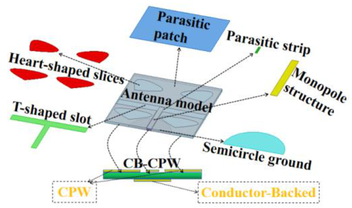
2. Analysis and Design of the Antenna

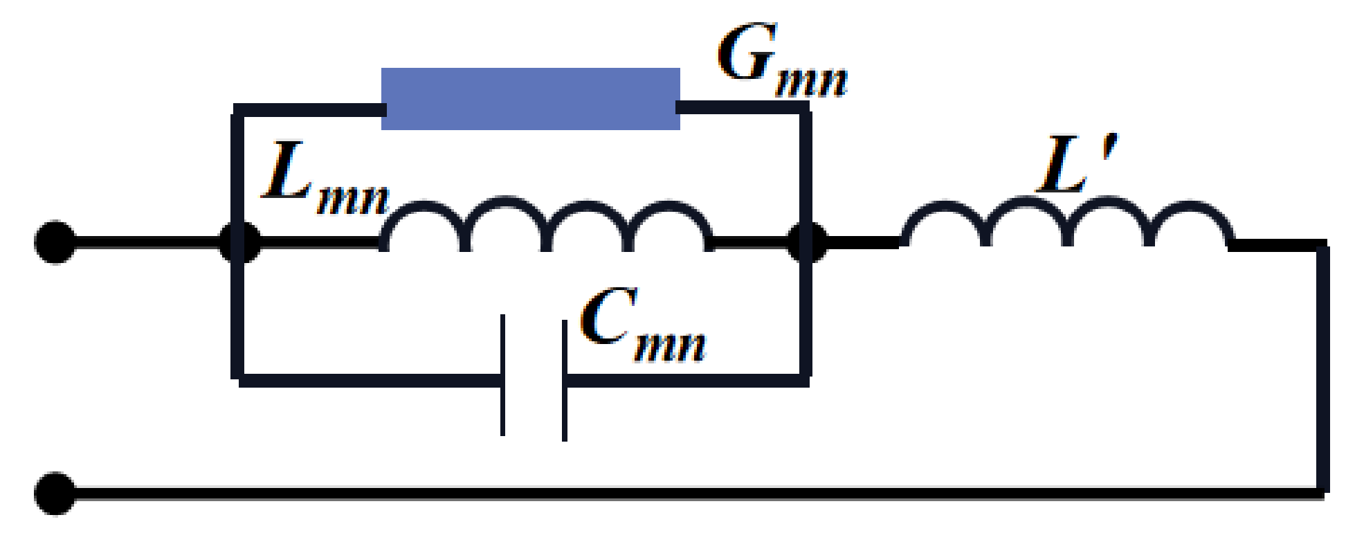
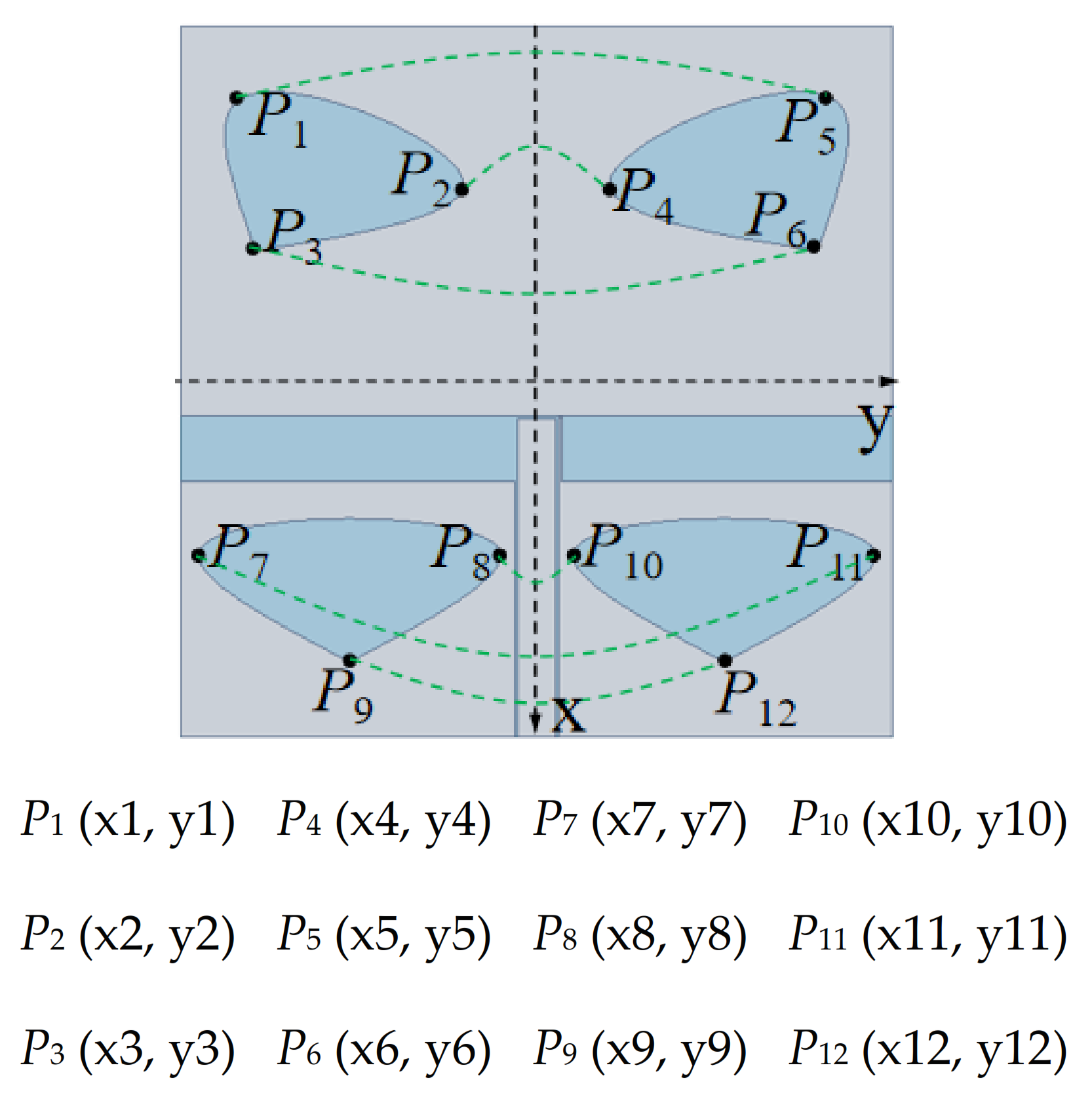
2.1. Antenna Analysis
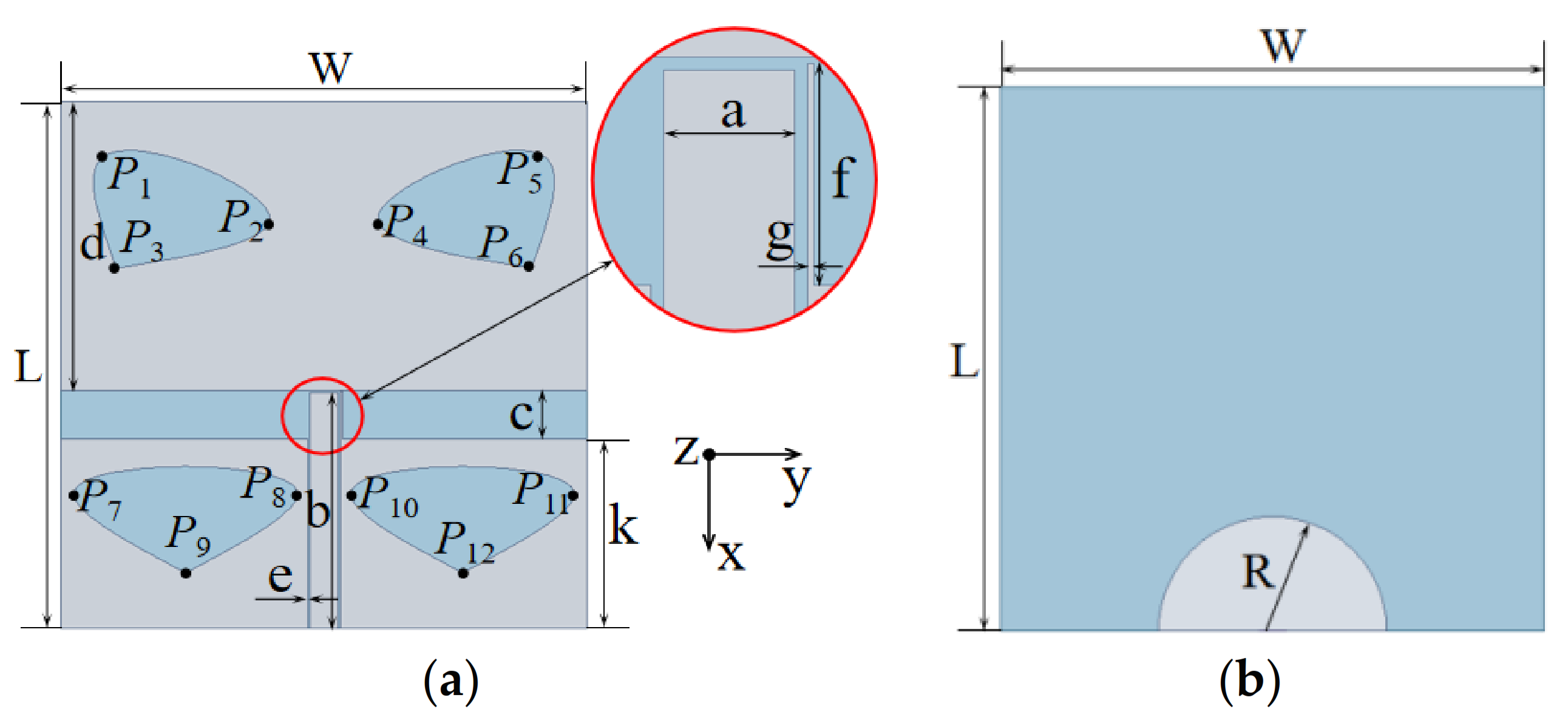
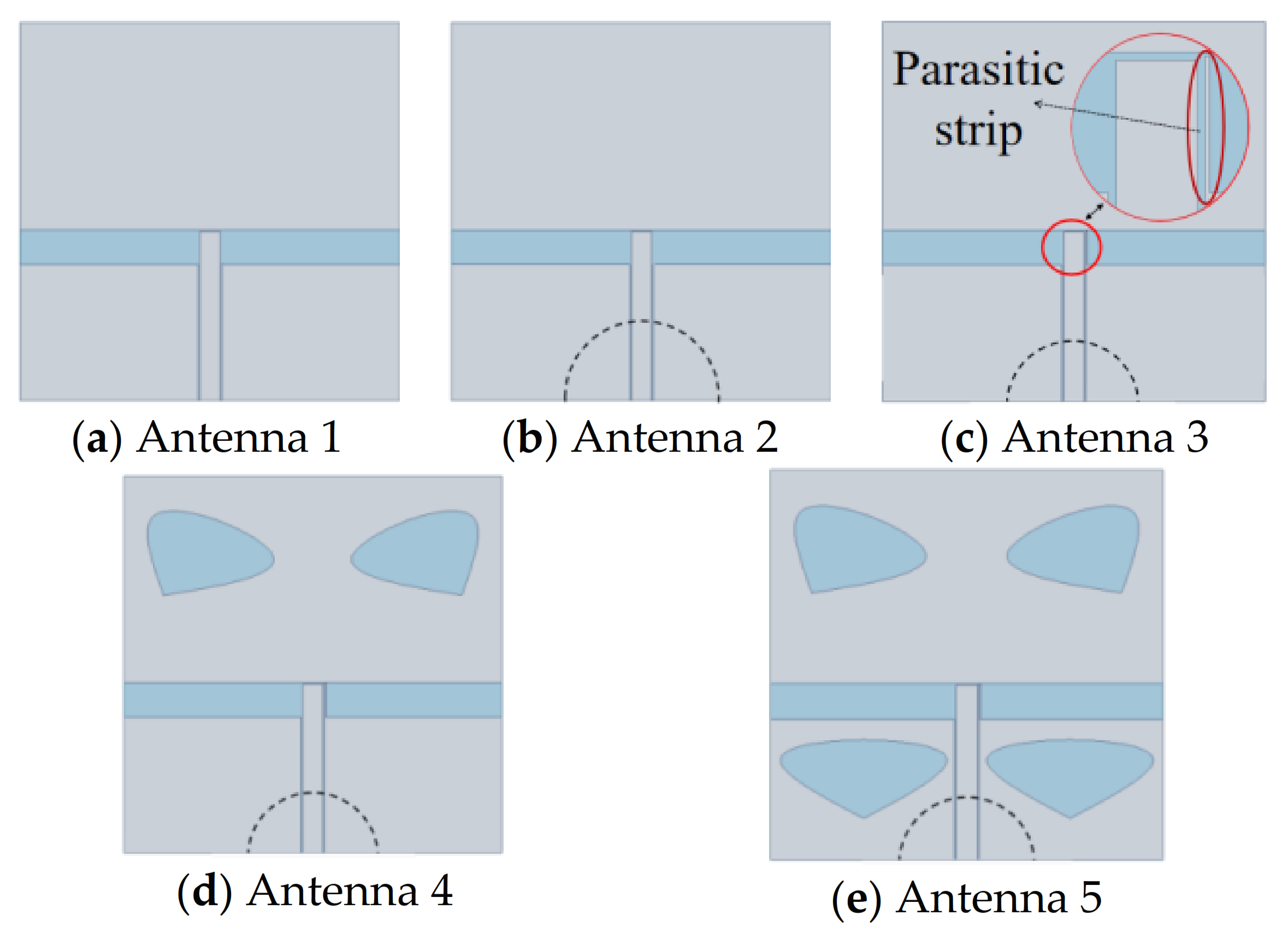
Impedance matching is important in the design of antennas. Antennas that achieve impedance matching can transmit power efficiently. However, impedance mismatching leads to the generation of various unnecessary reflection signals and recoil signals. The impedance matching quality of antennas is usually measured by voltage standing wave ratio (VSWR), reflection coefficient (S11) and other parameters. The gain, efficiency and input impedance of the antenna are also critical factors influencing the performance of antennas. During the designing process, a parasitic strip and heart-shaped slices were added to the antenna to acquire the effect of resonance.
CB-CPW is composed of semicircle ground and CPW, which belongs to parallel plate mode. The coupling of CB-CPW can lead to a sharp decrease in impedance and an increase in reflection coefficient—that is, an increase in bandwidth. It has good heat dissipation effect and high mechanical strength.
The resonant frequency of the CB-CPW structure in [23] can be expressed as:
f m n = c 2 ε r m / w g 2 + n / l g 2 0.5
where εr is the relative permittivity of the material, c is the speed of light, wg and lg are the width and length of the ground plane at both ends of the CB-CPW, respectively, and m and n are factors of the resonant mode.
Figure 2 shows the simplified equivalent circuit model, where L 0 . The input impedance of the TMmn mode is:
Z i n 1 G m n + j [ ω C m n 1 / ( ω L m n ) ]
Equation (2) may also be rewritten as:
Z i n = 1 1 + j Q [ f / f m n f m n / f ] = R m n 1 + j Q S
S = f f m n f m n f = ± ρ 1 Q ρ
where ρ denotes the voltage standing wave ratio (VSWR).
The relative bandwidth is:
B W = f H f L f m n × 100 % = ρ 1 Q ρ × 100 %
D = P ( θ , φ ) max 1 4 π P ( θ , φ ) d Ω
G = η D
where fH is the highest frequency point and fL is the lowest frequency point of 10 dB.
The resonant frequency of the equivalent circuit is:
f o = 1 2 π L m n C m n
The directivity coefficient D is the ratio of the peak energy to the average energy at a specific angle. Considering the loss of the antenna, the gain G is equal to the directivity coefficient multiplied by the antenna efficiency. The antenna efficiency is also the ratio of antenna radiation power to input power. If the loss of the feeder system is included, the antenna gain is called the actual gain.

2.2. Antenna Design

The geometry and dimensions of the proposed novel broadband monopole antenna are shown in Figure 3. The antenna was designed on a single-layer FR4 (Epoxy glass cloth laminate) substrate with a dielectric constant of 4.4 and a loss tangent of 0.02. Other units of the antenna were made of copper. This design was analyzed and studied by high frequency structure simulator (HFSS) software, and some size parameters of the antenna were optimized and compared. In the main mode, the lumped port was used to excite the transmission line and a 50-Ω load was introduced into the design.
Figure 4 shows five kinds of antennas. Antenna 1 is a common monopole T-slot antenna. Antenna 2 is prepared by adding a semicircular ground plane to Antenna 1. Antenna 3 is made by embedding a parasitic strip into Antenna 2. The structures of Antenna 4 and Antenna 5 are obtained by cutting heart-shaped slices off from Antenna 3. It can be seen from Figure 5 that after adding the parasitic strip to the CPW of Antenna 3, a bandwidth of 10 dB was achieved, and the bandwidth of Antenna 5 is larger than that of Antenna 3, indicating that heart-shaped slices could greatly enlarge the bandwidth. Parallel strip is very important to bandwidth expansion. The reason why antennas with irregular slots have a wider bandwidth is because they have stronger resonance effects. The symmetrical slots on the patch also resonated with each other. Symmetrical slots on two sides of the feed line are impedance-matched when they are coupled with the feed line, thus improving the S11.
According to Figure 5, the bandwidth of Antenna 5 is the largest, and its simulation bandwidth is 3.42 GHz (4.87–8.29 GHz). The two peak points of its bandwidth are 10.826 and 10.632 dB, which are all greater than 10 dB. Therefore, Antenna 5 excites TM10, TM20 and TM30 modes and realizes three resonant points.
To facilitate the cutting, three pairs of X-axis-symmetrical P points were located to make a single heart-shaped slice, as shown in Figure 6, where P of each heart shape corresponds to the values of x and y (x1 = −20, x2 = −16, x3 = −12, x7 = 4, x8 = 4, x9 = 10, y1 = −16, y2 = −4, y3 = −15, y7 = −18, y8 = −2, y9 = −10; unit: mm).
Figure 7 optimizes the parameters of the transmission line length, b, and the T-slot width, c, of the antenna. When b = 17.1 mm and c = 3.5 mm, the antenna had the widest broadband. Figure 8 modifies the radius, R, of the back circle of the antenna as well as the length, f, and width, g, of the parasitic strip. When R = 9.1 mm, f = 3.4 mm and g = 0.1 mm, the antenna achieved the optimal broadband function. The simulation results showed that the center frequency was 6.58 GHz and the maximum return loss was 39.29 dB at 5.1 GHz. When S11 ≤ −10 dB, fH = 8.29 GHz and fL = 4.87 GHz, the absolute bandwidth, B, and the relative bandwidth, Br, were fHfL = 3.42 GHz and 52%, respectively.
As indicated by Figure 9, the current of the proposed antenna at three different frequencies was mostly distributed on the monopole transmission line and the feed line but rarely at the edge of the slot. There was no strong current distribution on the semicircle ground.

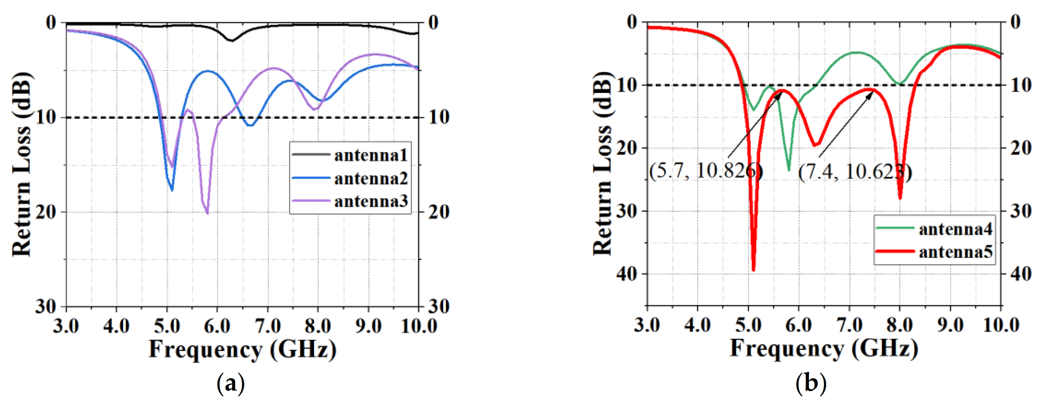
3. Simulation and Measurement
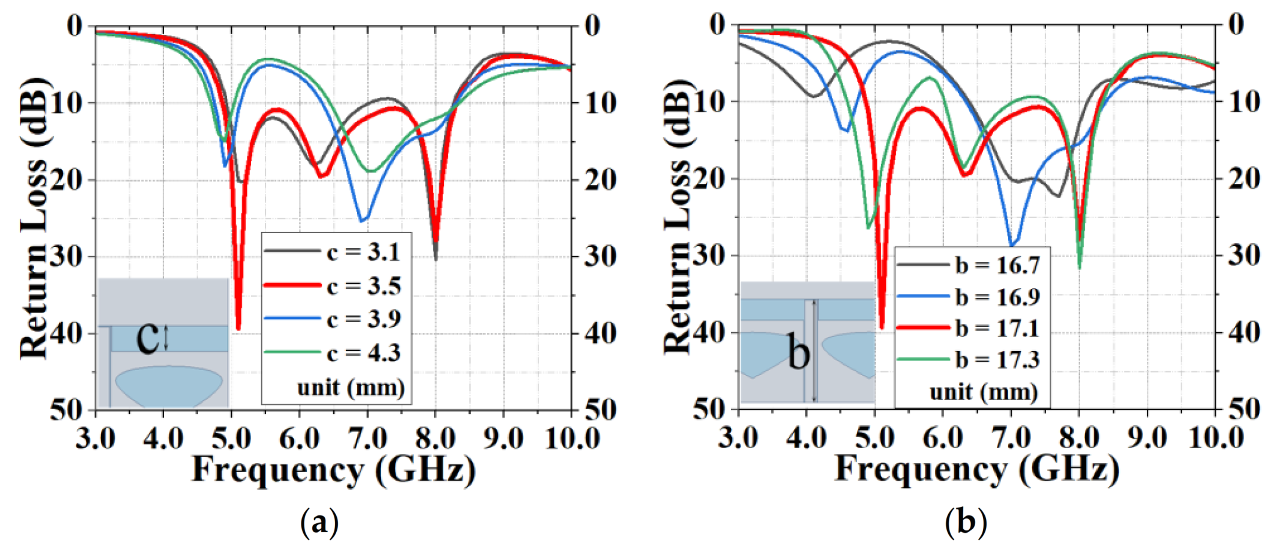
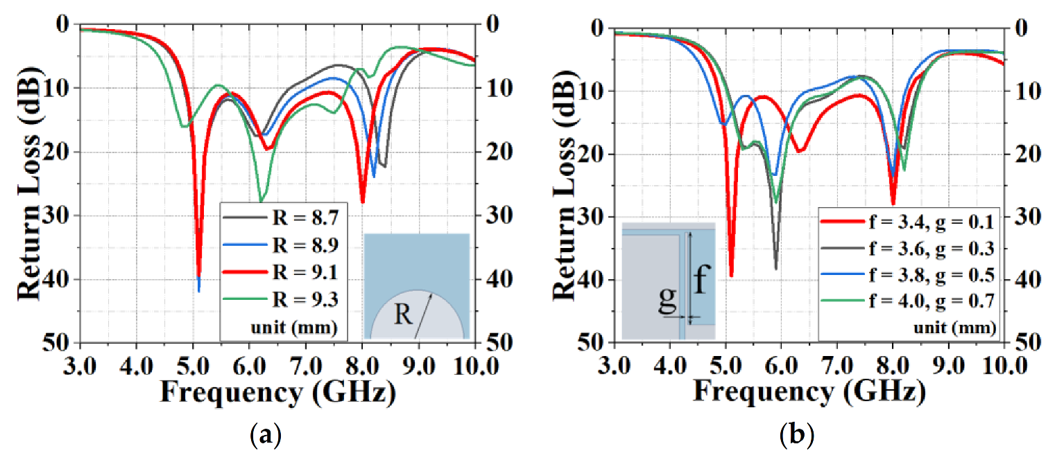
The antenna was processed and measured precisely to verify its feasibility. In the measurement process, the antenna was calibrated and the cable loss was reduced. Figure 10 illustrates the fabricated prototype with photos. The center frequency of the antenna was 6.7 GHz, the maximum call return loss was 39.89 dB at 8.33 GHz, the bandwidth was 10 dB at 4.02 GHz (Figure 11a), the VSWR was less than 2 at 5–6 GHz (Figure 11b), the gain was 0.01–3.31 dBi at 5–6 GHz (Figure 12a) and the efficiency was 79.01–90.9% at 5–6 GHz (Figure 12b). The measurement result of the standing wave was excellent and its flatness was within 1.5. The measured antenna bandwidth was larger than the simulated antenna bandwidth, and the measurement effect was obvious. It shows that the measurement and simulation (theoretical and practical) have a certain error, but the impact is small, and the measured data and simulation data of the antenna are basically consistent.
Figure 13a–f present the 2D radiation patterns (E- and H-plane) simulated and measured at 5.8, 5.5 and 5.2 GHz, respectively. According to those figures, the antenna almost achieved omnidirectional radiation. The measurement and simulation results of the designed antenna were basically consistent.
Table 1 compares several antennas, each of which has its own advantages and innovations. According to the measurement results, the antenna has a bandwidth of 4.02 GHz (4.69–8.71 GHz), a relative bandwidth of 60%, a maximum gain of 3.31 dBi and a maximum efficiency of 91.1%. The performance of the ultra-wideband (UWB) is realized with high efficiency and suitable gain. The antenna proposed in this paper had a smaller size and a wider bandwidth.

4. Discussion

The results of this study suggest that a miniaturized patch antenna with extended bandwidth can be realized after parameter optimization by ANSYS HFSS (Ver. 15). This paper analyzed the return loss of the antenna to observe its bandwidth. It can be seen from the design part that when a T-slot and parasitic patch are inserted, the broadband effect is not ideal. When a parasitic strip is added, the antenna has a bandwidth of about 1 GHz. Furthermore, cutting into two heart-shaped slots does not change, and cutting into four heart-shaped slots has a broadband effect, achieving ultra-wideband performance. This kind of antenna is also based on CPW structure. Many kinds of structure combinations excite the resonance effect to obtain the required broadband antenna.
Compared with Table 1, the bandwidths of the antennas in references [24,29] are wider than that in this paper, but their gain and efficiency are lower. Similarly, the gain of the antenna in reference [25] is lower than that in this paper, and the efficiency of the antenna in reference [32] is lower than the proposed antenna. The antenna size of this paper is the smallest compared with the references in Table 1. From Figure 12, it can be seen that the gain of the antenna is relatively smooth and the antenna has strong stability. For the cross-polarized pattern, the E-plane can radiate in all directions. Generally speaking, the design of the antenna unit in this paper is in accordance with the theoretical results. If necessary, at a later stage, the antenna in this paper can continue to be expanded in this theory, and this paper can be extended to the broadband array structure in the future.
There were minor errors between the measurement and simulation (theoretical and practical) data, and the impact was small, which may be caused by several reasons. First, the resonance frequency of the processed antenna may be higher, and frequency offset leads to this kind of error. Second, the reason may be related to the HFSS software, such as the establishment of the model and the way of feeding. Third, the test cable loss, the accuracy of antenna processing, the feed welding during the test and the antenna test environment also possibly resulted in the difference between the measured and the simulated data.

5. Conclusions

A novel broadband monopole antenna is presented in this paper. Its VSWR bandwidth is measured to be 4.02 GHz (4.69 to 8.71 GHz), its efficiency is 73.8% to 91.1% at 5–8.5 GHz and its peak gain is 3.31 dBi. This broadband and miniaturized antenna is easy to process and assemble, with fast heat-dissipating speed, a low cost, small radiation loss, high mechanical strength and a beautiful appearance. Therefore, it has broad application prospects. It can operate in the frequency bands of ISM (5.725–5.850 GHz), RFID (5.8 GHz) and WLAN (5.15–5.25 GHz and 5.725–5.825 GHz).

Author Contributions

Study design and writing, Z.D.; methodology, H.W.; project administration, S.T.; conceptualization, D.Z.; data curation, C.M.; investigation, Y.Z. All authors have read and agreed to the published version of the manuscript.

Funding

This research was funded by the National Natural Science Foundation of China, grant numbers 31170668 and 61701240, and State Key Laboratory of Millimeter Waves of China, grant number K201920.

Acknowledgments

The authors would like to thank the National Natural Science Foundation of China and Professor Chunping Chen of Kanagawa University in Japan for financially supporting this research.

Conflicts of Interest

The authors declare no conflict of interest.

References

  1. Gui, G.; Liu, F.; Sun, J.; Yang, J.; Zhou, Z.; Zhao, D. Flight Delay Prediction Based on Aviation Big Data and Machine Learning. IEEE Trans. Veh. Technol. 2020, 69, 140–150. [Google Scholar] [CrossRef]
  2. Wang, Y.; Du, Z. A Printed Dual-Antenna System Operating in the GSM1800/GSM1900/UMTS/LTE2300/LTE2500/ 2.4-GHz WLAN Bands for Mobile Terminals. IEEE Antennas Wirel. Propag. Lett. 2014, 13, 233–236. [Google Scholar] [CrossRef]
  3. Cui, Y.; Li, R.; Wang, P. A Novel Broadband Planar Antenna for 2G/3G/LTE Base Stations. IEEE Trans. Antennas Propag. 2013, 61, 2767–2774. [Google Scholar] [CrossRef]
  4. Fang, X.; Wen, G.; Inserra, D.; Huang, Y.; Li, J. Compact Wideband CPW-Fed Meandered-Slot Antenna with Slotted Y-Shaped Central Element for Wi-Fi, WiMAX, and 5G Applications. IEEE Trans. Antennas Propagat. 2018, 66, 7395–7399. [Google Scholar] [CrossRef]
  5. Basar, E. Reconfigurable Intelligent Surface-Based Index Modulation: A New Beyond MIMO Paradigm for 6G. IEEE Trans. Commun. 2020, 68, 3187–3196. [Google Scholar] [CrossRef] [Green Version]
  6. Wang, J.; Wong, H.; Ji, Z.; Wu, Y. Broadband CPW-Fed Aperture Coupled Metasurface Antenna. IEEE Antennas Wirel. Propagat. Lett. 2019, 18, 517–520. [Google Scholar] [CrossRef]
  7. Alsariera, H.; Zakaria, Z.; Isa, A.A.M. A Broadband P-Shaped Circularly Polarized Monopole Antenna with a Single Parasitic Strip. IEEE Antennas Wirel. Propagat. Lett. 2019, 18, 2194–2198. [Google Scholar] [CrossRef]
  8. Zhang, Z.; Zhao, Y.; Zuo, S.; Yang, L.; Ji, L.; Fu, G. A Broadband Horizontally Polarized Omnidirectional Antenna for VHF Application. IEEE Trans. Antennas Propagat. 2018, 66, 2229–2235. [Google Scholar] [CrossRef]
  9. Cao, Y.; Cai, Y.; Cao, W.; Xi, B.; Qian, Z.; Wu, T.; Zhu, L. Broadband and High-Gain Microstrip Patch Antenna Loaded with Parasitic Mushroom-Type Structure. IEEE Antennas Wirel. Propag. Lett. 2019, 18, 1405–1409. [Google Scholar] [CrossRef]
  10. Lu, J.; Zhang, H.C.; He, P.H.; Zhang, L.P.; Cui, T.J. Design of Miniaturized Antenna Using Corrugated Microstrip. IEEE Trans. Antennas Propagat. 2020, 68, 1918–1924. [Google Scholar] [CrossRef]
  11. Wang, M.; Zhu, X.; Guo, Y.; Wu, W. Miniaturized Dual-Band Circularly Polarized Quadruple Inverted-F Antenna for GPS Applications. IEEE Antennas Wirel. Propagat. Lett. 2018, 17, 1109–1113. [Google Scholar] [CrossRef]
  12. Gyasi, K.O.; Wen, G.; Inserra, D.; Huang, Y.; Li, J.; Ampoma, A.E.; Zhang, H. A Compact Broadband Cross-Shaped Circularly Polarized Planar Monopole Antenna with a Ground Plane Extension. IEEE Antennas Wirel. Propag. Lett. 2018, 17, 335–338. [Google Scholar] [CrossRef]
  13. Tang, Z.; He, Y. Broadband microstrip antenna with U and T slots for 2.45/2.41 GHz RFID tag. Electron. Lett. 2009, 45, 926–928. [Google Scholar] [CrossRef]
  14. Chen, S.; Wang, D.; Tu, W. Dual-Band/Tri-Band/Broadband CPW-Fed Stepped-Impedance Slot Dipole Antennas. IEEE Trans. Antennas Propagat. 2014, 62, 485–490. [Google Scholar] [CrossRef]
  15. Zhang, H.; Zhang, F.; Zhang, F.; Li, T.; Li, C. Bandwidth Enhancement of a Horizontally Polarized Omnidirectional Antenna by Adding Parasitic Strips. IEEE Antennas Wirel. Propagat. Lett. 2017, 16, 880–883. [Google Scholar] [CrossRef]
  16. Dong, Y.; Choi, J.; Itoh, T. Folded Strip/Slot Antenna with Extended Bandwidth for WLAN Application. IEEE Antennas Wirel. Propagat. Lett. 2017, 16, 673–676. [Google Scholar] [CrossRef]
  17. Cheng, T.; Jiang, W.; Gong, S.; Yu, Y. Broadband SIW Cavity-Backed Modified Dumbbell-Shaped Slot Antenna. IEEE Antennas Wirel. Propagat. Lett. 2019, 18, 936–940. [Google Scholar] [CrossRef]
  18. Xu, K.D.; Xu, H.; Liu, Y.; Li, J.; Liu, Q.H. Microstrip Patch Antennas with Multiple Parasitic Patches and Shorting Vias for Bandwidth Enhancement. IEEE Access 2018, 6, 11624–11633. [Google Scholar] [CrossRef]
  19. Chakraborty, U.; Kundu, A.; Chowdhury, S.K.; Bhattacharjee, A.K. Compact Dual-Band Microstrip Antenna for IEEE 802.11a WLAN Application. IEEE Antennas Wirel. Propagat. Lett. 2014, 13, 407–410. [Google Scholar] [CrossRef]
  20. Han, D.; Kim, J.; Park, S. A Dual Band CMOS Receiver with Hybrid Down Conversion Mixer for IEEE 802.11a/b/g/n WLAN Applications. IEEE Microw. Wirel. Compon. Lett. 2010, 20, 235–237. [Google Scholar] [CrossRef]
  21. Lu, J.; Lee, Y. Planar compact triple-band monopole antenna for IEEE 802.16 m worldwide interoperability for microwave access system. IET Microw. Antennas Propagat. 2013, 7, 1045–1054. [Google Scholar] [CrossRef]
  22. Jeng, S.; Chen, J.; Tsung, C.; Lu, Y. Coverage probability analysis of IEEE 802.16 system with smart antenna system over stanford university interim fading channels. IET Commun. 2010, 4, 91–101. [Google Scholar] [CrossRef]
  23. Kilani, M.B.; Nedil, M.; Kandil, N.; Yagoub, M.C.E.; Denidni, T.A. Wideband directional elliptic coupler based on CB-CPW technology. Electron. Lett. 2012, 48, 710–712. [Google Scholar] [CrossRef]
  24. Saini, R.K.; Dwari, S.; Mandal, M.K. CPW-Fed Dual-Band Dual-Sense Circularly Polarized Monopole Antenna. IEEE Antennas Wirel. Propagat. Lett. 2017, 16, 2497–2500. [Google Scholar] [CrossRef]
  25. Ding, K.; Gao, C.; Wu, Y.; Qu, D.; Zhang, B. A Broadband Circularly Polarized Printed Monopole Antenna with Parasitic Strips. IEEE Antennas Wirel. Propagat. Lett. 2017, 16, 2509–2512. [Google Scholar] [CrossRef]
  26. See, C.H.; Abd-Alhameed, R.A.; Abidin, Z.Z.; McEwan, N.J.; Excell, P.S. Wideband Printed MIMO/Diversity Monopole Antenna for WiFi/WiMAX Applications. IEEE Trans. Antennas Propagat. 2012, 60, 2028–2035. [Google Scholar] [CrossRef] [Green Version]
  27. Li, Q.; Feresidis, A.P.; Mavridou, M.; Hall, P.S. Miniaturized Double-Layer EBG Structures for Broadband Mutual Coupling Reduction between UWB Monopoles. IEEE Trans. Antennas Propagat. 2015, 63, 1168–1171. [Google Scholar] [CrossRef]
  28. Ding, Z.; Zhang, D.; Ma, C. Broadband Antenna Design with Integrated CB-CPW and Parasitic Patch Structure for WLAN, RFID, Wimax, and 5G Applications. IEEE Access 2020, 8, 42877–42883. [Google Scholar] [CrossRef]
  29. Alibakhshikenari, M.; Virdee, B.S.; See, C.H.; Abd-Alhameed, R.; Ali, A.; Falcone, F.; Limiti, E. Wideband printed monopole antenna for application in wireless communication systems. IET Microw. Antennas Propag. 2018, 12, 1222–1230. [Google Scholar] [CrossRef]
  30. Wang, C.; Chen, C. CPW-Fed Stair-Shaped Slot Antennas with Circular Polarization. IEEE Trans. Antennas Propagat. 2009, 57, 2483–2486. [Google Scholar] [CrossRef]
  31. Ying Chiou, J.; Sze, J.Y.; Wong, K.L. A broad-band CPW-fed strip-loaded square slot antenna. IEEE Trans. Antennas Propagat. 2003, 51, 719–721. [Google Scholar] [CrossRef]
  32. Jin, Z.; Yun, T. Compact Wideband Open-End Slot Antenna with Inherent Matching. IEEE Antennas Wirel. Propagat. Lett. 2014, 13, 1385–1388. [Google Scholar] [CrossRef]
Figure 1. Explosive decomposition structure.
Sensors 20 07002 g001
Figure 2. The simplified equivalent circuit model (established when wmn is isolated from all other resonant frequencies).
Sensors 20 07002 g002
Figure 3. Geometric configuration of the proposed antenna: (a) top side and (b) bottom side, where L = W = 38 mm; H = 1 mm; R = 9.1 mm; a = 2 mm; b = 17.1 mm; c = 3.5 mm; d = 20.7 mm; e = 0.1 mm; f = 3.4 mm; g = 0.1 mm; k = 13.8 mm.
Sensors 20 07002 g003
Figure 4. Geometry comparison of five types of antennas.
Sensors 20 07002 g004
Figure 5. Comparison of return losses of five antennas with different shapes.
Sensors 20 07002 g005
Figure 6. Symmetry analysis of the heart-shaped structure.
Sensors 20 07002 g006
Figure 7. Improvement of the return loss by optimizing (a) transmission line length, b, and (b) T-slot width, c.
Sensors 20 07002 g007
Figure 8. Improvement of the return loss by optimizing (a) the radius, R, of the back circle of the antenna and (b) the length, f, and width, g, of the parasitic strip.
Sensors 20 07002 g008
Figure 9. Simulated surface current distribution of the proposed novel antenna at frequencies of 5.2 (a), 5.5 (b) and 5.8 (c) GHz.
Sensors 20 07002 g009
Figure 10. Photo of the front and the back of the designed antenna.
Sensors 20 07002 g010
Figure 11. Comparison of simulated and measured (a) return loss and (b) voltage standing wave ratio (VSWR) of the designed antenna.
Sensors 20 07002 g011
Figure 12. Comparison of simulated and measured (a) gain and (b) radiation efficiency of the designed antenna.
Sensors 20 07002 g012
Figure 13. The measured and simulated 2D radiation patterns of the proposed antenna. (a) E-plane at 5.2 GHz. (b) H-plane at 5.2 GHz. (c) E-plane at 5.5 GHz. (d) H-plane at 5.5 GHz. (e) E-plane at 5.8 GHz. (f) H-plane at 5.8 GHz.
Sensors 20 07002 g013
Table 1. Comparison between the proposed Antenna 1 and previously designed antennas.
Ref.Size (mm3)Imp. Bandwidth
(GHz, %)
Max Gain
(dBi)
Max Efficiency
(%)
[24]63 × 75 × 1.61.81–1.63, 71.63%2.590%
[25]55 × 50 × 11.75–4.5, 88%2.395%
[26]90 × 40 × 0.792.4–4.2, 54.5%3/
[27]60 × 50 × 1.53.44–6.13, 56.2%/89%
[28]40 × 40 × 14.83–8.17, 55%3.87/
[29]48 × 43 × 0.80.115–2.90, 185%2.3578.85%
[30]60 × 40 × 0.82.3–3.15, 31.2%3.7/
[31]70 × 70 × 1.61.5–2.5, 50%5.8/
[32]50 × 50 × 11.71–3.66, 73.3%480%
Proposed38 × 38 × 14.69–8.71, 60%3.3191.1%
Publisher’s Note: MDPI stays neutral with regard to jurisdictional claims in published maps and institutional affiliations.

