Economical Auto Moment Limiter for Preventing Mobile Cargo Crane Overload

 , ,
, , 
Abstract
1. Introduction
2. State-of-the-Art in AML Based on Maximum Lifting Load Prediction
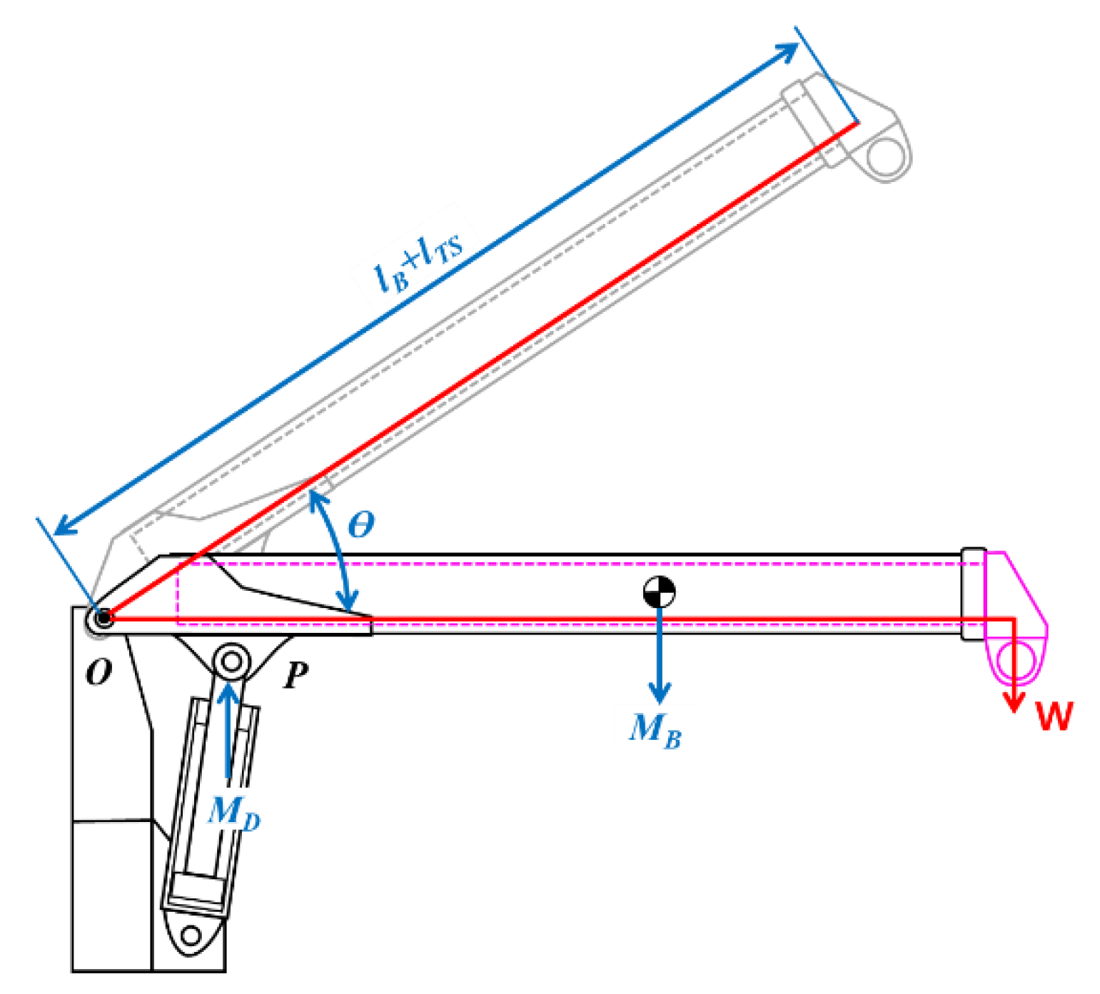
3. Computational Method of the Allowable Lifting Load Using the Pressure on the Derrick Cylinder and the Boom Angle
3.1. Formulation of the Mathematical Model of the Allowable Lifting Load
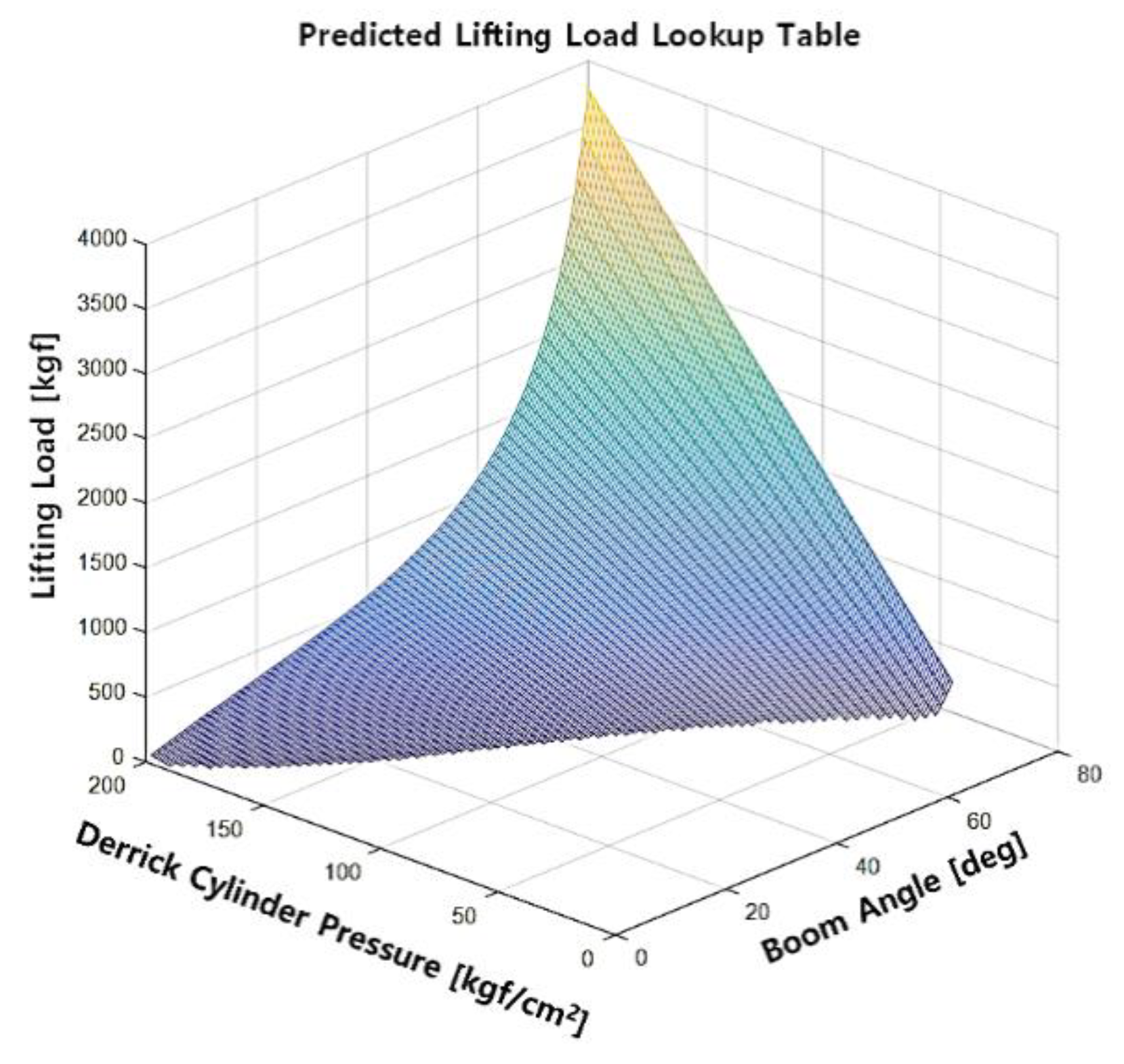
3.2. Computational Procedure for the Lifting Capacity Analysis by Considering the Pressure and Boom Angle
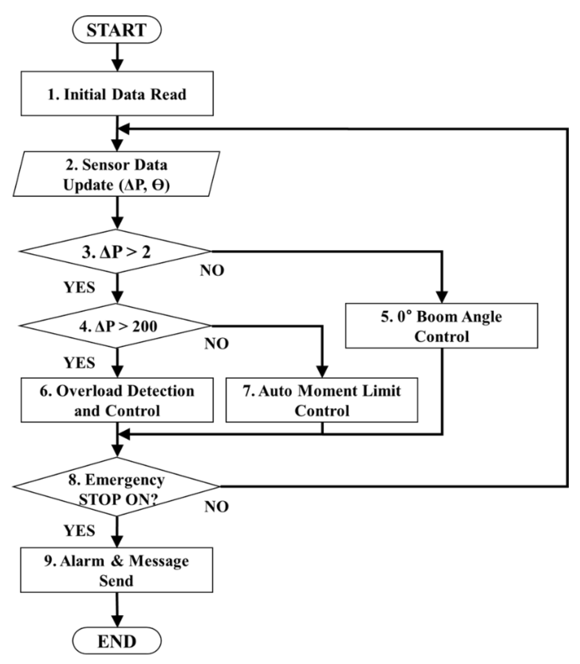
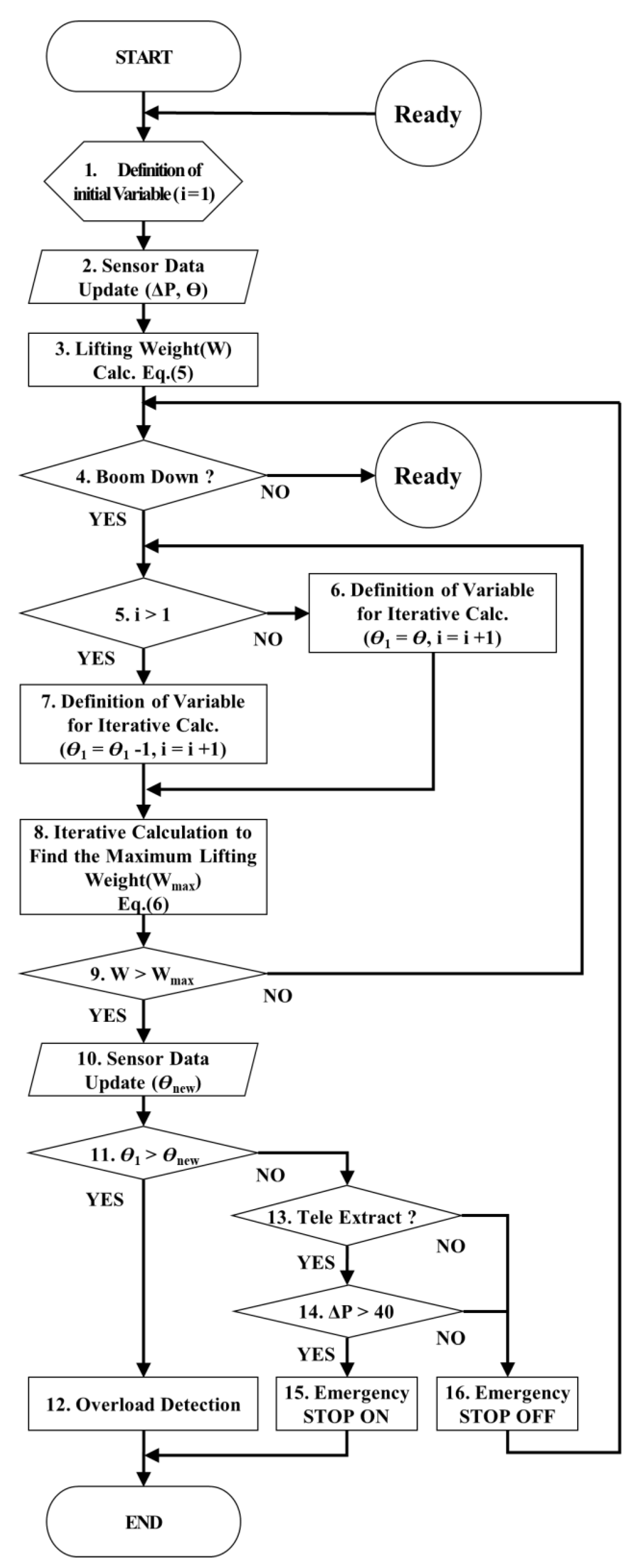
4. Algorithm Controlling the eAML
4.1. Manipulating the Boom Angle at 0°
4.2. Detecting and Controlling Overload
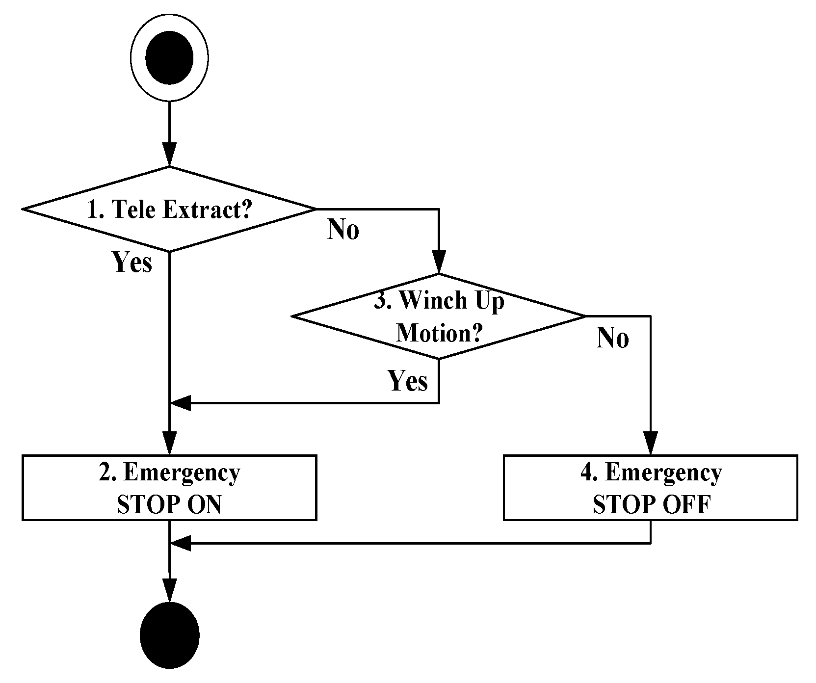
4.3. Controlling the eAML
5. Verification Experiment
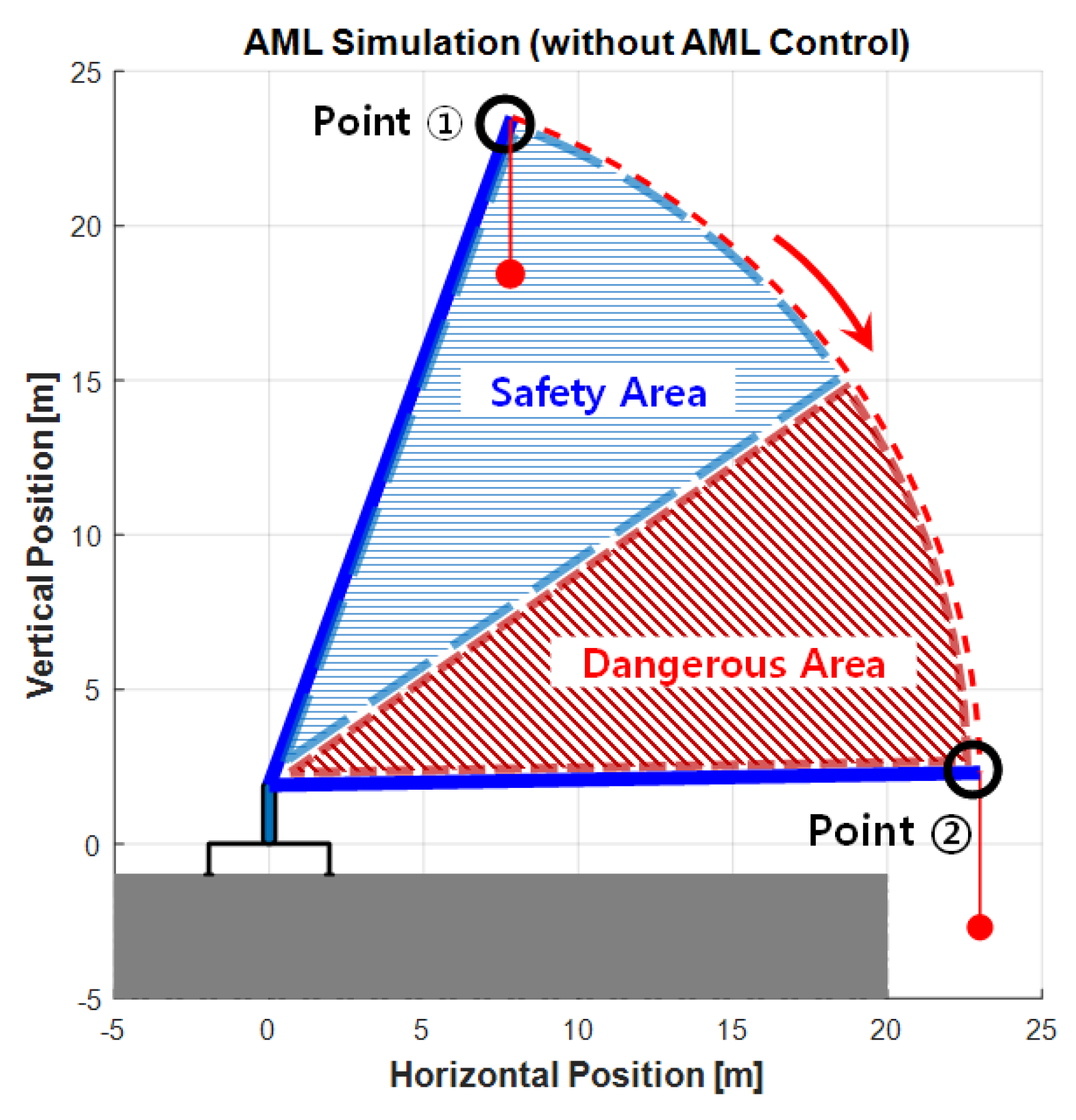
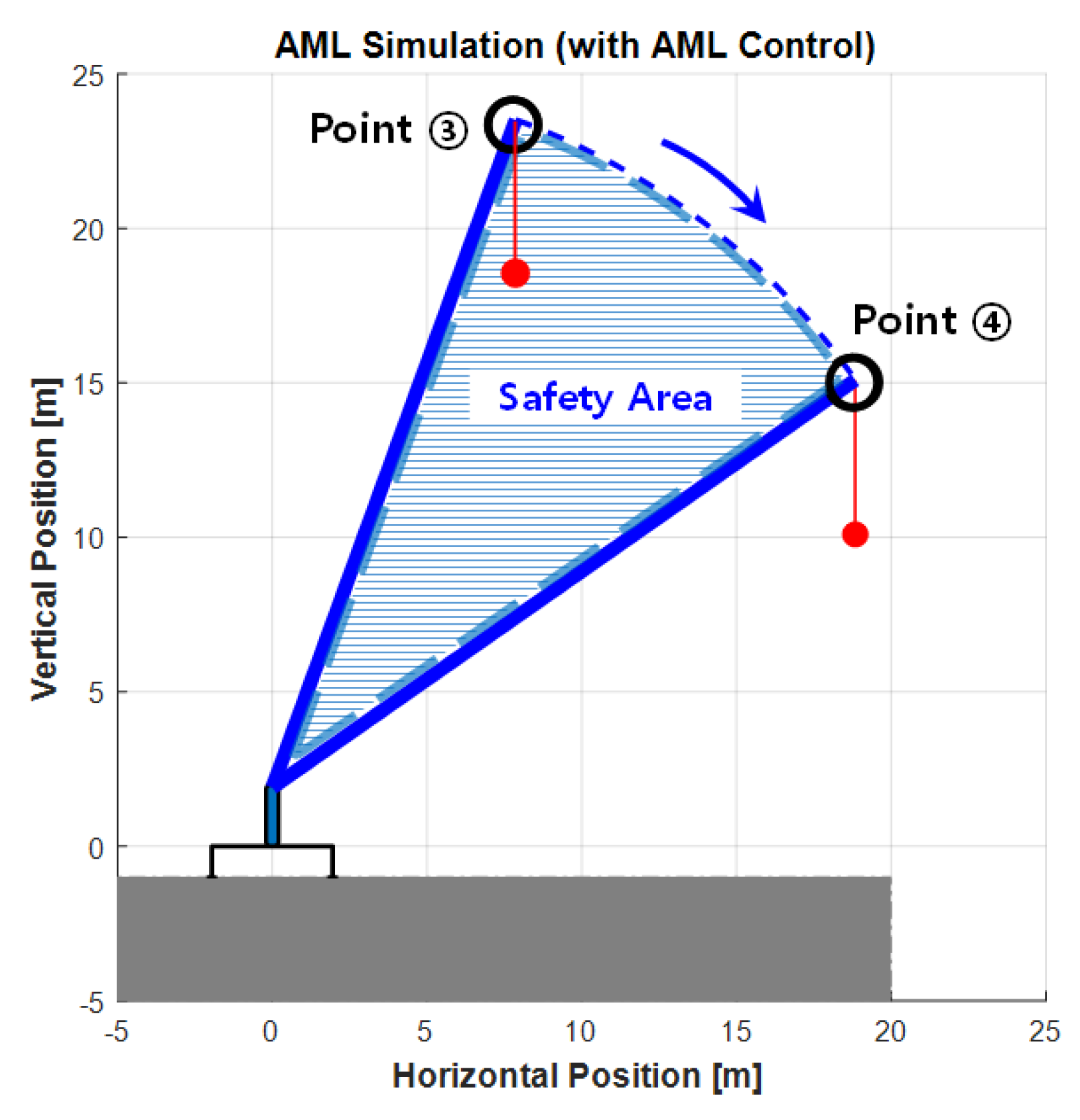
5.1. eAML Simulation Using the Maximum Lifting Load Prediction Method
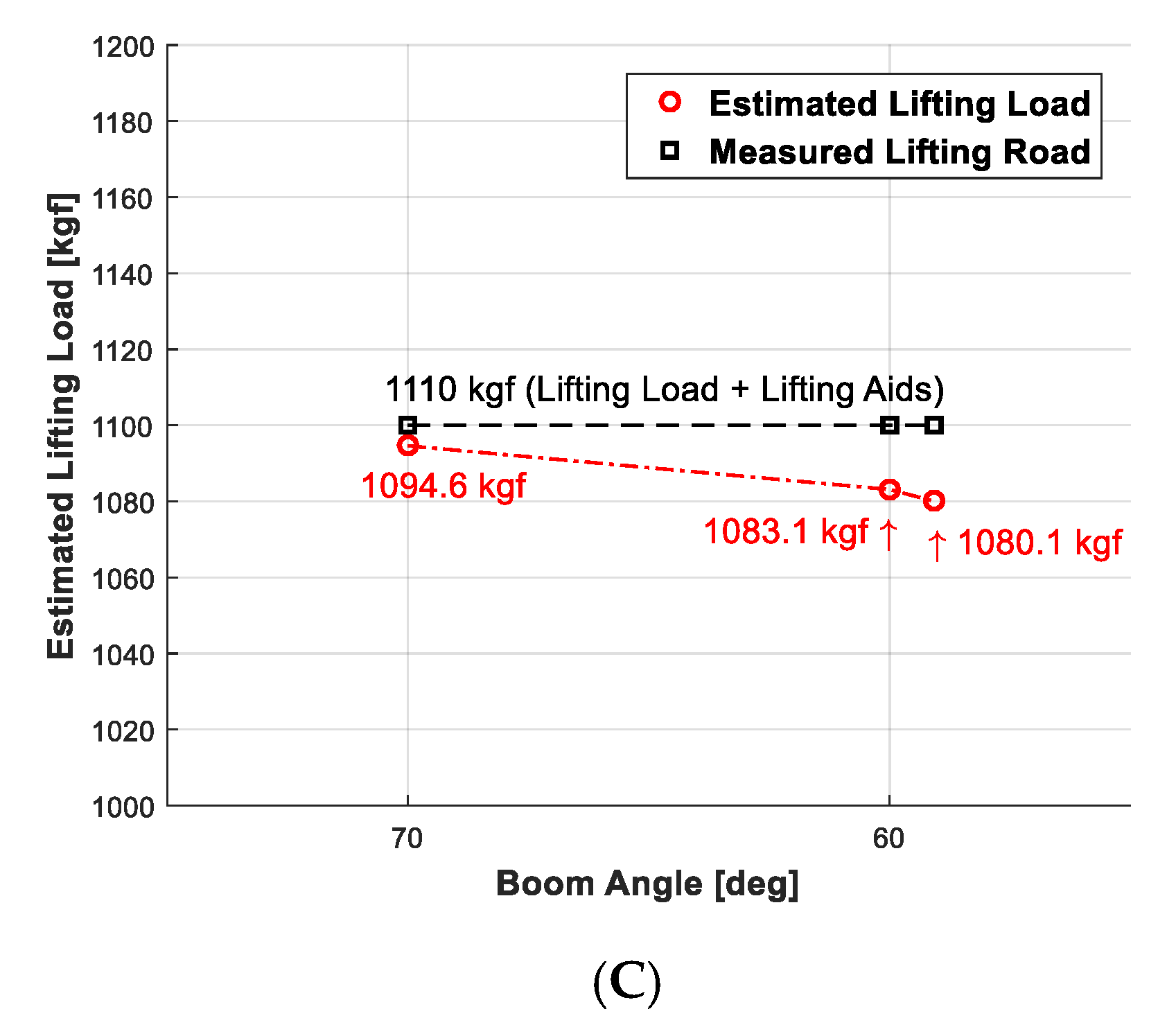
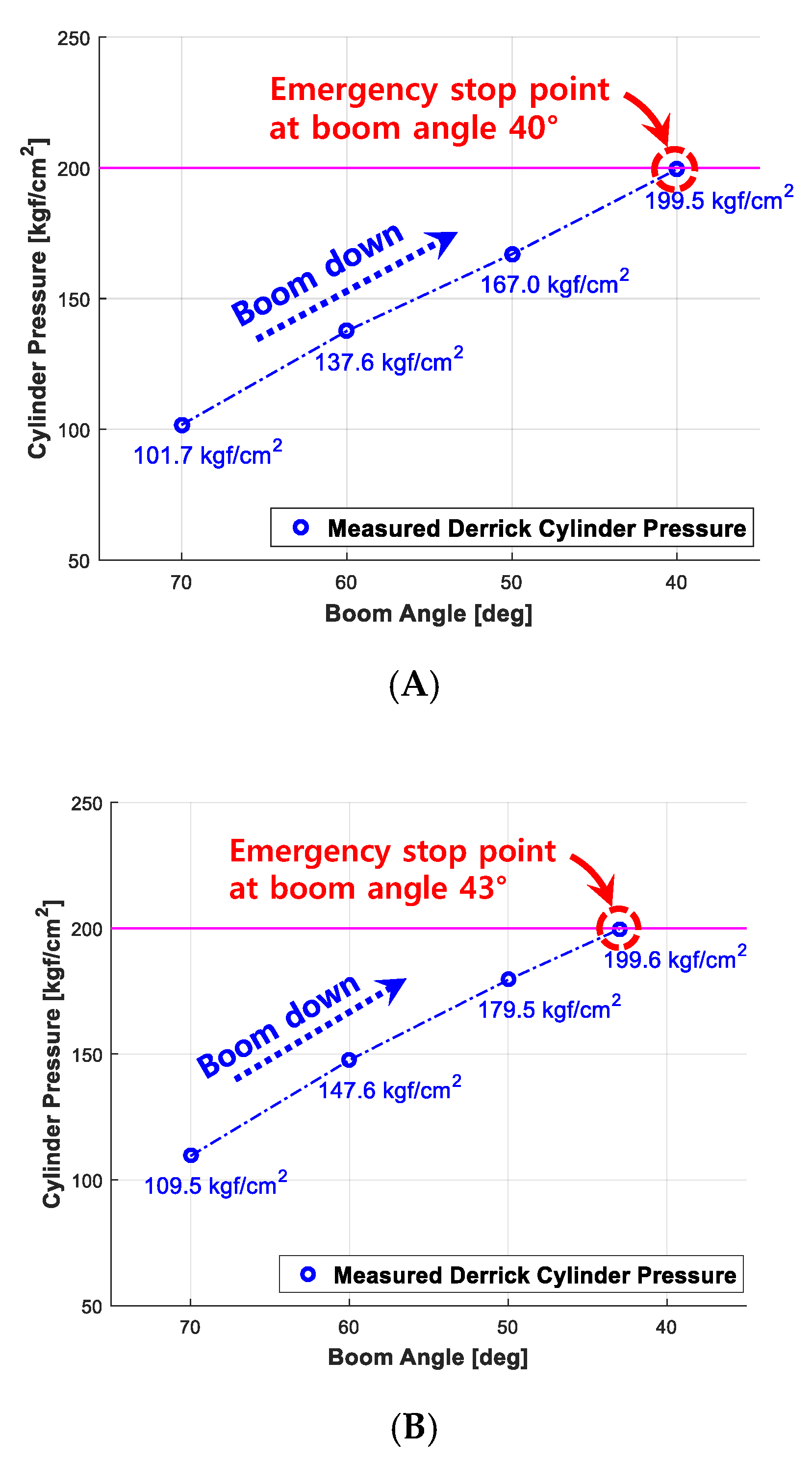
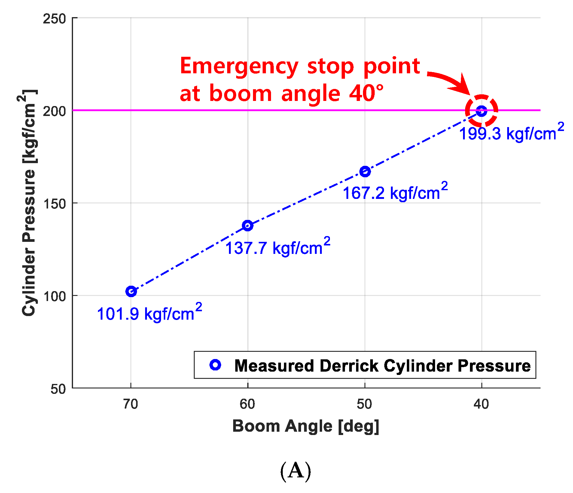
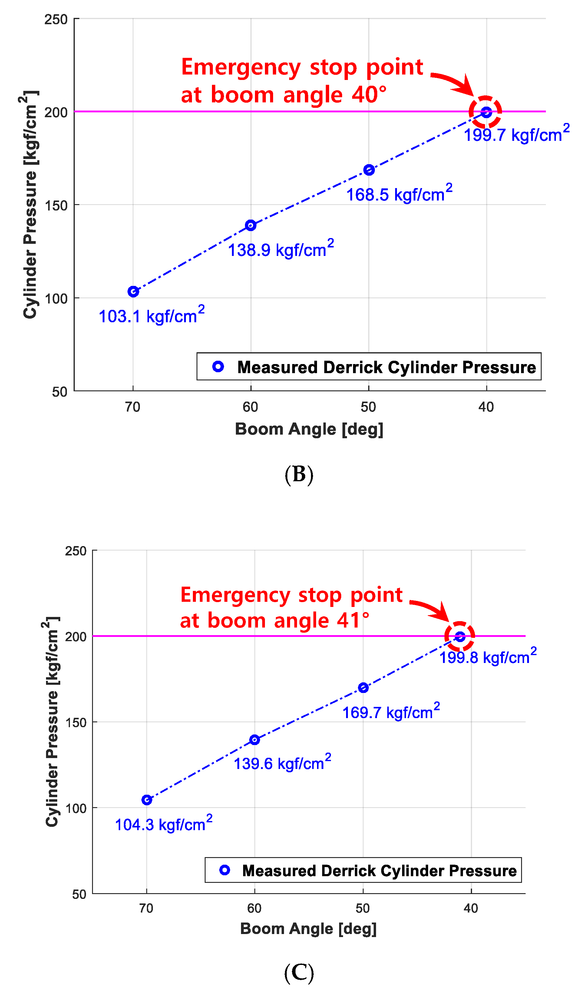
5.2. Validation of the eAML
5.2.1. Experiment Method
5.2.2. Experiment Outputs
Validation of Performance Reliability
Validation of Robustness to Wind
5.3. Predicting the Allowable Lifting Loads Using eAML Simulation Outputs
6. Conclusions
Author Contributions
Funding
Conflicts of Interest
Notation
| D | internal diameter of a derrick cylinder |
| lB | Initial length before boom extension |
| lB1 | distance from point O to the center of mass of the first boom |
| lB2 | distance from point O to the center of mass of the second boom |
| ldl | distance after the derrick cylinder extends |
| ldl_i | initial distance before the derrick cylinder extends |
| lTR | distance from point O to the center of mass of a telescopic cylinder (rod) |
| lTS | length after boom extension |
| lTT | distance from point O to the center of mass of a telescopic cylinder (tube) |
| MB | moment of force caused by the boom’s own weight |
| MD | moment of force caused by the derrick cylinder’s own weight |
| O | rotation center of the boom |
| P | center point connecting a derrick cylinder with a boom |
| R | rotational radius of a derrick cylinder |
| W | lifting load of a cargo crane |
| WB1 | weight of the first boom |
| WB2 | weight of the second boom |
| Wmax | maximum lifting load of a crane |
| Wmax_bc | best-fit curve of the maximum lifting load |
| WTR | rod weight of a telescopic cylinder |
| WTT | tube weight of a telescopic cylinder |
| α | assembly angle of a derrick cylinder |
| β | angle between the centerline of the derrick cylinder and an imaginary line connecting points o and p |
| ΔP | tube pressure of a derrick cylinder |
| θ | luffing angle of the boom |
| θ1 | luffing angle variable to find the maximum lifting weight |
| θc | luffing angle at which the boom can descend the lowest based on its current angle |
| θnew | luffing angle of the boom measured in real time |
References
- Suruda, A.; Liu, D.; Egger, M.; Lillquist, D. Fatal injuries in the United States construction industry involving cranes 1984–1994. J. Occup. Environ. Med. 1999, 41, 1052–1058. Available online: https://journals.lww.com/joem/Abstract/1999/12000/Fatal_Injuries_in_the_United_States_Construction.8.aspx (accessed on 30 October 2020). [CrossRef] [PubMed]
- Nishizaki, H.; Yonekura, K.O.; Tsuji, Y. U.S. Patent 3,971,008. 1976. Available online: https://patents.google.com/patent/US3971008A/en (accessed on 30 October 2020).
- Ho, J.K. Choosing Mobile Crane and Developing the Simulation Program of Stability Review. Rev. Archit. Build. Sci. 2007, 51, 91–95. Available online: https://www.aik.or.kr/html/page04_05.jsp (accessed on 30 October 2020).
- Pietzsch, L.; Huhne, G.; Overlach, K.; Fuchs, P. U.S. Patent 4,057,792. 1977. Available online: https://patents.google.com/patent/US4057792A/en (accessed on 30 October 2020).
- Lee, H.S.; Jo, M.G.; Cha, Y.T.; Shin, D.Y.; Choi, S.J.; Kim, J.H. Development prospect of a traveling crane. J. Drive Control 2013, 10, 41–46. Available online: http://www.koreascience.or.kr/article/JAKO201329063579731.pub (accessed on 30 October 2020).
- Park, J.S. Improvement of Overload Prevention Device Performance for Mobile Telescopic Boom Crane (No. 2018-OSHRI-895); Occupational Safety & Health Research Institute: Bucheon-si, Korea, 2018; Available online: http://oshri.kosha.or.kr/oshri/publication/researchReportSearch.do?mode=view&articleNo=408267&article.offset=0&articleLimit=10&srSearchVal=%EC%9D%B4%EB%8F%99%EC%8B%9D+%ED%81%AC%EB%A0%88%EC%9D%B8 (accessed on 30 October 2020).
- Fukagawa, R.; Muroa, T. Alarm system to prevent the overturning of truck cranes considering possible ground failure. In Automation and Robotics in Construction Xi; Elsevier: Amsterdam, The Netherlands, 1994; pp. 27–34. [Google Scholar] [CrossRef]
- Yang, J.; Qiu, L.J. AMLU truck crane torque instrument working set and analysis. Advanced Materials Research; Trans Tech Publications Ltd., 2012; Volume 424, pp. 1037–1040. Available online: https://www.scientific.net/AMR.424-425.1037 (accessed on 30 October 2020).
- Qiu, L.J.; Yang, J. Design and Control on Automobile Crane Torque Limiter. Appl. Mech. Mater. 2012, 201, 657–660. [Google Scholar] [CrossRef]
- Kuromoto, K. U.S. Patent No. 5,823,369. 1998. Available online: https://patents.google.com/patent/US5823369A/en (accessed on 30 October 2020).
- Han, D.S.; Ha, J.M.; Han, G.J. Development of many-angular pin type load cell for a overload limiter of a movable crane. Key Eng. Mater. 2009, 413, 291–298. [Google Scholar] [CrossRef]
- Garaffo, G.; Giorlando, R.; Muscarello, R. Development of a Test Bench for Calibration of Load Moment Limiter Used in Mobile Crane. 2017. Available online: http://ceur-ws.org/Vol-1852/ (accessed on 30 October 2020).
- DAS. Auto Moment Limiter System. Available online: http://www.das-co.com/product/product_view.htm?product_category=04010100&idx=6963 (accessed on 1 April 2020).
- Kilicslan, S.; Balkan, T.; Ider, S.K. Tipping loads of mobile cranes with flexible booms. J. Sound Vib. 1999, 223, 645–657. [Google Scholar] [CrossRef]
- Sun, G.; Liu, J. Dynamic responses of hydraulic crane during luffing motion. Mech. Mach. Theory 2006, 41, 1273–1288. [Google Scholar] [CrossRef]
- Posiadala, B.; Skalmierski, B.; Tomski, L. Motion of the lifted load brought by a kinematic forcing of the crane telescopic boom. Mech. Mach. Theory 1990, 25, 547–556. [Google Scholar] [CrossRef]
- Sun, G.; Kleeberger, M. Dynamic responses of hydraulic mobile crane with consideration of the drive system. Mech. Mach. Theory 2003, 38, 1489–1508. [Google Scholar] [CrossRef]
- Oguamanam, D.C.D.; Heppler, G.R. Dynamics of a three-dimensional overhead crane system. J. Sound Vib. 2001, 242, 411–426. [Google Scholar] [CrossRef]
- Towareck, Z. The dynamic stability of a crane standing on solid during the rotating of the boom. Int. J. Mech. Sci. 1998, 40, 557–574. [Google Scholar] [CrossRef]
- Jerman, B.; Podrzaj, P.; Kramar, J. An investigation of slewing-crane dynamics during slewing motion-development and verification of a mathematical model. Int. J. Mech. Sci. 2004, 46, 729–750. [Google Scholar] [CrossRef]
- Shaikh, A.A. Lifting capacity enhancement of a crawler crane by improving stability. J. Theor. Appl. Mech. 2016, 54, 219–227. [Google Scholar] [CrossRef]
- Park, S.O. The Crane Includeing the Antiover-Loading System Using Differential Pressure Switch, Kr. Patent No. 10-0736719, 2 July 2007. Available online: https://doi.org/10.8080/1020050032991 (accessed on 29 October 2020).
- Sugimoto, Y.; Seki, H.; Samo, T.; Nakamitsu, N. 4D CAD-based evaluation system for crane deployment plans in construction of nuclear power plants. Autom. Constr. 2016, 71, 87–98. [Google Scholar] [CrossRef]
- Khodabandelu, A.; Park, J.; Arteaga, C. Crane operation planning in overlapping areas through dynamic supply selection. Autom. Constr. 2020, 117, 103253. [Google Scholar] [CrossRef]
- Ji, Y.; Leite, F. Automated tower crane planning: Leveraging 4-dimensional BIM and rule-based checking. Autom. Constr. 2018, 93, 78–90. [Google Scholar] [CrossRef]
- Nadoushani, Z.S.M.; Hammad, A.W.A.; Akbarnezhad, A. Location Optimization of Tower Crane and Allocation of Material Supply Points in a Construction Site Considering Operating and Rental Costs. ASCE J. Constr. Eng. Manag. 2016, 143, 04016089. [Google Scholar] [CrossRef]
- Al Hattab, M.; Zankoul, E.; Hamzeh, F.R. Near-Real-Time Optimization of Overlapping Tower Crane Operations: A Model and Case Study. ASCE J. Comput. Civ. Eng. 2017, 31, 05017001. [Google Scholar] [CrossRef]
- Li, X.; Chi, H.L.; Wu, P.; Shen, G.Q. Smart work packaging-enabled constraint-free path re-planning for tower crane in prefabricated products assembly process. Adv. Eng. Inform. 2020, 43, 101008. [Google Scholar] [CrossRef]
- Marzouk, M.; Abubakr, A. Decision support for tower crane selection with building information models and genetic algorithms. Autom. Constr. 2015, 61, 1–15. [Google Scholar] [CrossRef]
- Younes, A.; Marzouk, M. Tower cranes layout planning using agent-based simulation considering activity conflicts. Autom. Constr. 2018, 93, 348–360. [Google Scholar] [CrossRef]
- Zhou, W.; Zhao, T.; Liu, W.; Tang, J. Tower crane safety on construction sites: A complex sociotechnical system perspective. Saf. Sci. 2018, 109, 95–108. [Google Scholar] [CrossRef]
- Sadeghi, S.; Soltanmohammadlou, N.; Rahnamayiezekavat, P. A systematic review of scholarly works addressing crane safety requirements. Saf. Sci. 2021, 133, 105002. [Google Scholar] [CrossRef]
- Fang, Y.; Choa, Y.K.; Chen, J. A framework for real-time pro-active safety assistance for mobile crane lifting operations. Autom. Constr. 2016, 72, 367–379. [Google Scholar] [CrossRef]
- Ren, W.; Wu, Z. Real-Time Anticollision System for Mobile Cranes during Lift Operations. ASCE J. Comput. Civ. Eng. 2015, 29, 04014100. [Google Scholar] [CrossRef]
- iDAS. DAS Application Technology (AML System). Available online: http://www.das-co.com/shop_contents/myboard_read.htm?load_type=&page_idx=0&tag_on=&h_search_c=0&h_search_v=&me_popup=&myboard_code=sub3&page_limit=200&idx=120596&page=1&category_idx= (accessed on 27 July 2020).


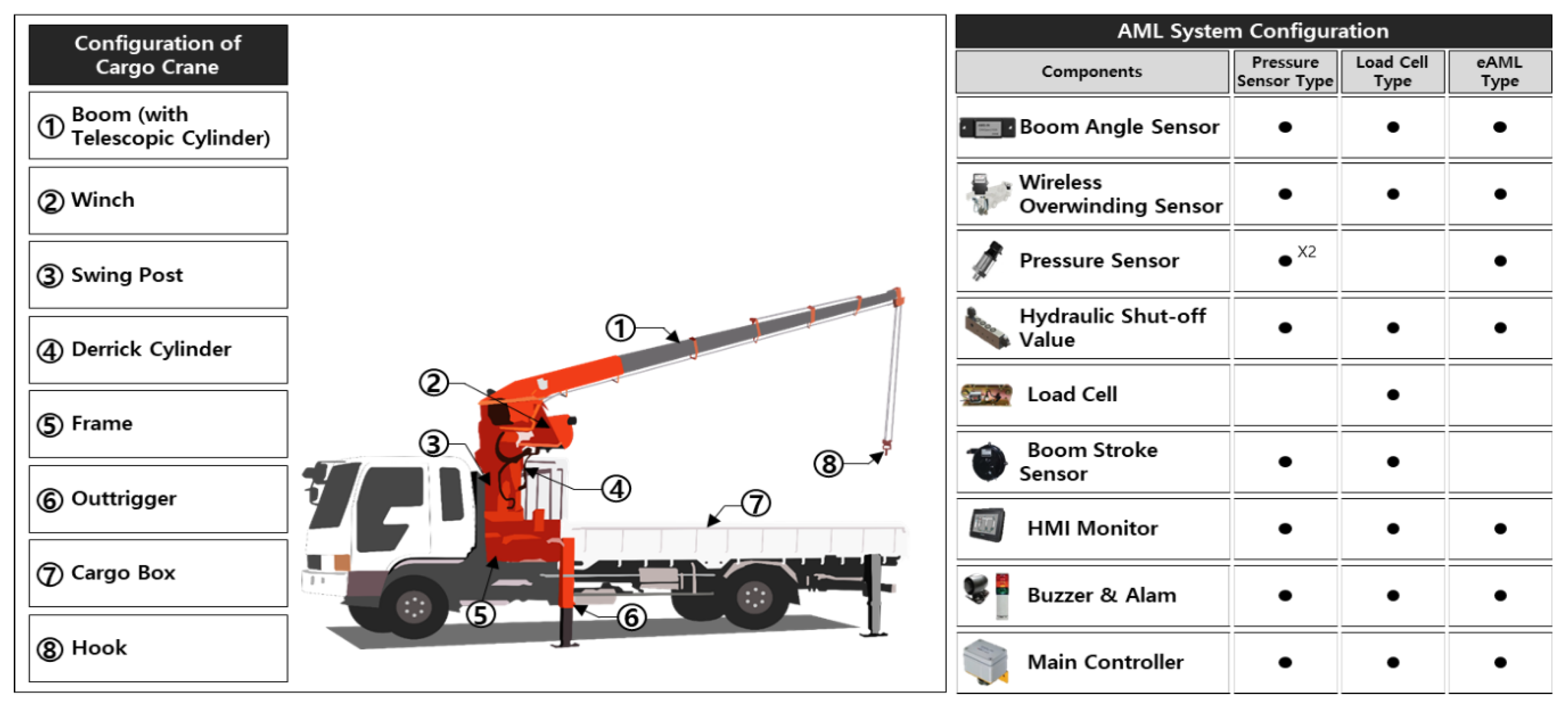
| Type | Advantages | Disadvantages | |
|---|---|---|---|
| Existing AML | Pressure-type AML | Lower price than the load cell-type AML | Undetectability of the overload pressure at 0° Poor durability |
| Load cell-type AML | Fall detection of derrick Detectability of pressure overload at 0° | Load cell sheave deformation High price Possibility of external overlap Poor durability | |
| eAML | Low-cost AML | Fall detection of derrick Detectability of pressure overload at 0° Low price | Necessity of initial calibration |
| Parameter | Notation | Value | Unit |
|---|---|---|---|
| Internal diameter (derrick cylinder) | D | 17 | cm |
| Rotational radius (derrick cylinder) | R | 588.8 | mm |
| Tube pressure (derrick cylinder) | ΔP | 0–200 | kgf/cm2 |
| Assembly angle (derrick cylinder) | α | 34 | deg |
| Luffing angle (boom) | Ɵ | 0–80 | deg |
| Initial distance (derrick cylinder) | ldl_i | 1568 | mm |
| Initial distance (boom) | lB | 19,995 | mm |
| Tele cylinder stroke | lTS | 2970 | mm |
| Weight of the first boom | WB1 | 460 | kgf |
| Distance to center of mass (first boom) | lB1 | 2650 | mm |
| Weight of the second boom | WB2 | 1200 | kgf |
| Distance to center of mass (second boom) | lB2 | 10,879 | mm |
| Rod weight (telescopic cylinder) | WTR | 80 | kgf |
| Distance to center of mass (telescopic cylinder rod) | lTR | 2246 | mm |
| Tube weight (telescopic cylinder) | WTT | 220 | kgf |
| Distance to center of mass (telescopic cylinder tube) | lTT | 7200 | mm |
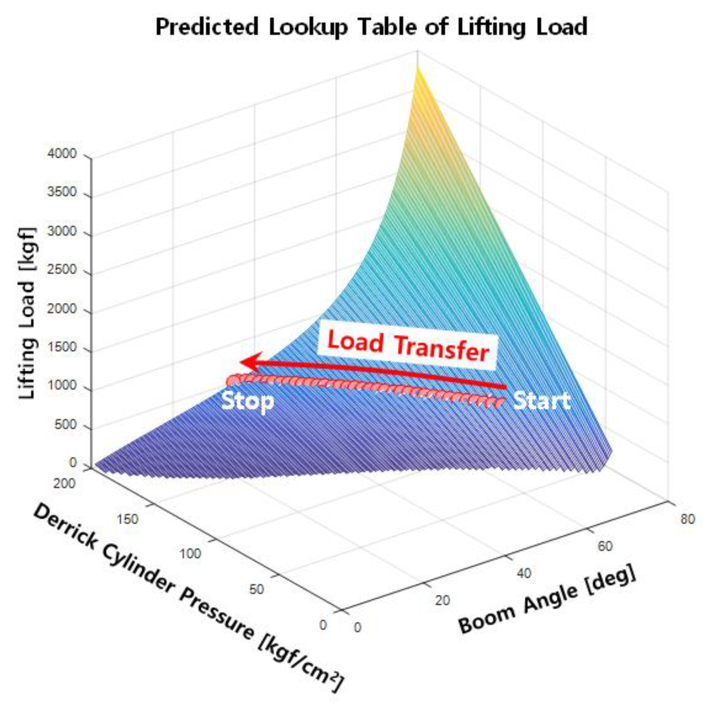
| Lifting Load W (kgf) | Boom Angle (°) θ | ||||||||
|---|---|---|---|---|---|---|---|---|---|
| 10 | 20 | 30 | 40 | 50 | 60 | 70 | 80 | ||
| Derrick cylinder pressure (kgf/cm2) ΔP | 40 | 122 | |||||||
| 45 | 237 | ||||||||
| 50 | 351 | ||||||||
| 55 | 466 | ||||||||
| 60 | 580 | ||||||||
| 65 | 46 | 695 | |||||||
| 70 | 111 | 810 | |||||||
| 75 | 175 | 925 | |||||||
| 80 | 240 | 1039 | |||||||
| 85 | 19 | 304 | 1154 | ||||||
| 90 | 67 | 369 | 1268 | ||||||
| 95 | 114 | 433 | 1383 | ||||||
| 100 | 162 | 498 | 1497 | ||||||
| 105 | 31 | 210 | 562 | 1612 | |||||
| 110 | 70 | 258 | 627 | 1726 | |||||
| 115 | 110 | 306 | 620 | 1841 | |||||
| 120 | 22 | 149 | 354 | 756 | 1956 | ||||
| 125 | 56 | 188 | 402 | 821 | 2070 | ||||
| 130 | 90 | 228 | 450 | 886 | 2185 | ||||
| 135 | 20 | 124 | 267 | 498 | 950 | 2299 | |||
| 140 | 50 | 158 | 306 | 545 | 1015 | 2414 | |||
| 145 | 81 | 192 | 346 | 593 | 1076 | 2528 | |||
| 150 | 15 | 111 | 226 | 385 | 641 | 1144 | 2642 | ||
| 155 | 42 | 141 | 260 | 424 | 688 | 1208 | 2757 | ||
| 160 | 69 | 171 | 294 | 464 | 736 | 1273 | 2872 | ||
| 165 | 96 | 201 | 328 | 503 | 784 | 1338 | 2987 | ||
| 170 | 16 | 123 | 232 | 362 | 542 | 832 | 1402 | 3101 | |
| 175 | 40 | 150 | 262 | 396 | 581 | 880 | 1467 | 3215 | |
| 180 | 64 | 177 | 292 | 430 | 621 | 928 | 1532 | 3330 | |
| 185 | 88 | 204 | 322 | 464 | 660 | 975 | 1596 | 3445 | |
| 190 | 111 | 231 | 352 | 498 | 700 | 1023 | 1661 | 3559 | |
| 195 | 135 | 257 | 382 | 532 | 739 | 1072 | 1725 | 3674 | |
| 200 | 160 | 284 | 412 | 566 | 779 | 1119 | 1790 | 3788 | |
| Experiment Items | Performance Reliability | Robustness to Wind |
|---|---|---|
| Method | Checking when the boom stops (when the maximum pressure of the derrick cylinder is 200 kgf/cm2) while lowering the angle of the boom from 70° to 0° (measured 30 times for each) with various weights. | Checking when the boom stops (when the maximum pressure of the derrick cylinder is 200 kgf/cm2) while lowering the angle of the boom from 70° to 0° (measured 30 times each) given an identical load (390 kgf) and different wind speeds. |
| Measurement attributes | , , W | , , W |
| Output variables | , , Wmax | , , Wmax |
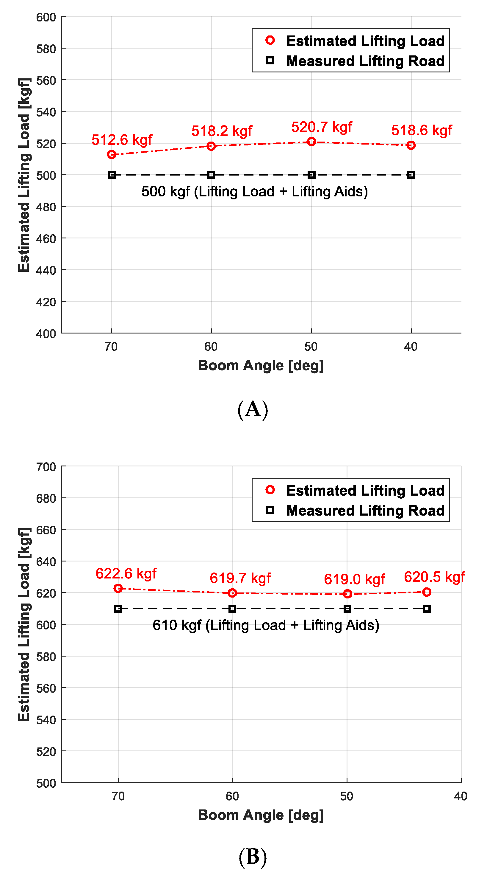
| Experiment object and environment | Loads of 390, 500, 1000 kgf; the lifting aids (i.e., hooks, auxiliary hooks, and sensors for validation) of 110 kgf. | The threshold of wind speed with a maximum 6 m/s or less. |
Publisher’s Note: MDPI stays neutral with regard to jurisdictional claims in published maps and institutional affiliations. |
© 2020 by the authors. Licensee MDPI, Basel, Switzerland. This article is an open access article distributed under the terms and conditions of the Creative Commons Attribution (CC BY) license (http://creativecommons.org/licenses/by/4.0/).
Share and Cite
Noh, S.-H.; Lee, Y.-S.; Kim, S.-H.; Cho, J.-S.; Han, C.-S.; Lee, S.-Y.; Lee, D.-E. Economical Auto Moment Limiter for Preventing Mobile Cargo Crane Overload. Sensors 2020, 20, 6355. https://doi.org/10.3390/s20216355
Noh S-H, Lee Y-S, Kim S-H, Cho J-S, Han C-S, Lee S-Y, Lee D-E. Economical Auto Moment Limiter for Preventing Mobile Cargo Crane Overload. Sensors. 2020; 20(21):6355. https://doi.org/10.3390/s20216355
Chicago/Turabian StyleNoh, Soo-Hoon, Yong-Seok Lee, Sang-Ho Kim, Jae-Sang Cho, Chang-Soo Han, Seung-Yeol Lee, and Dong-Eun Lee. 2020. "Economical Auto Moment Limiter for Preventing Mobile Cargo Crane Overload" Sensors 20, no. 21: 6355. https://doi.org/10.3390/s20216355
APA StyleNoh, S.-H., Lee, Y.-S., Kim, S.-H., Cho, J.-S., Han, C.-S., Lee, S.-Y., & Lee, D.-E. (2020). Economical Auto Moment Limiter for Preventing Mobile Cargo Crane Overload. Sensors, 20(21), 6355. https://doi.org/10.3390/s20216355