Wireless Sensing of Concrete Setting Process

 , , ,
, , ,  , and
, and
Abstract
:1. Introduction
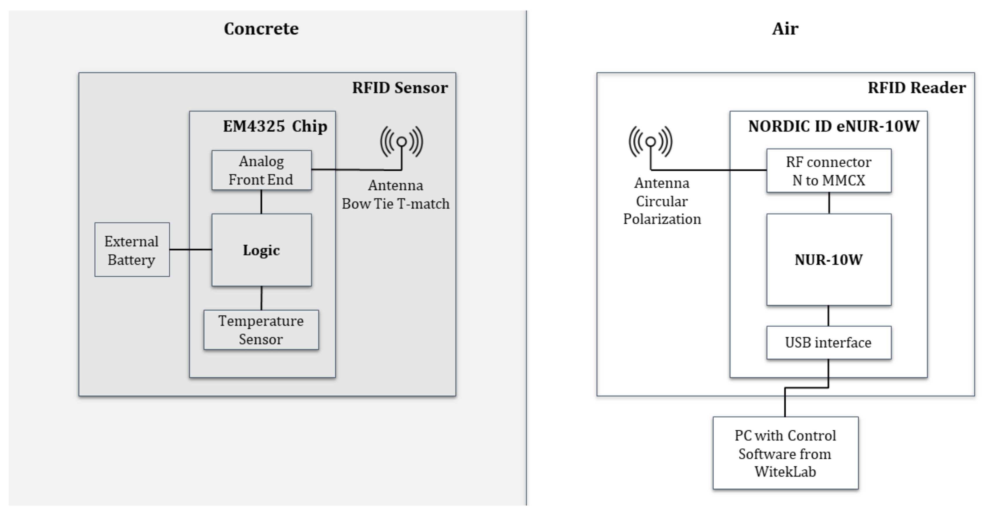
2. RFID-Based System for Wireless Temperature Monitoring
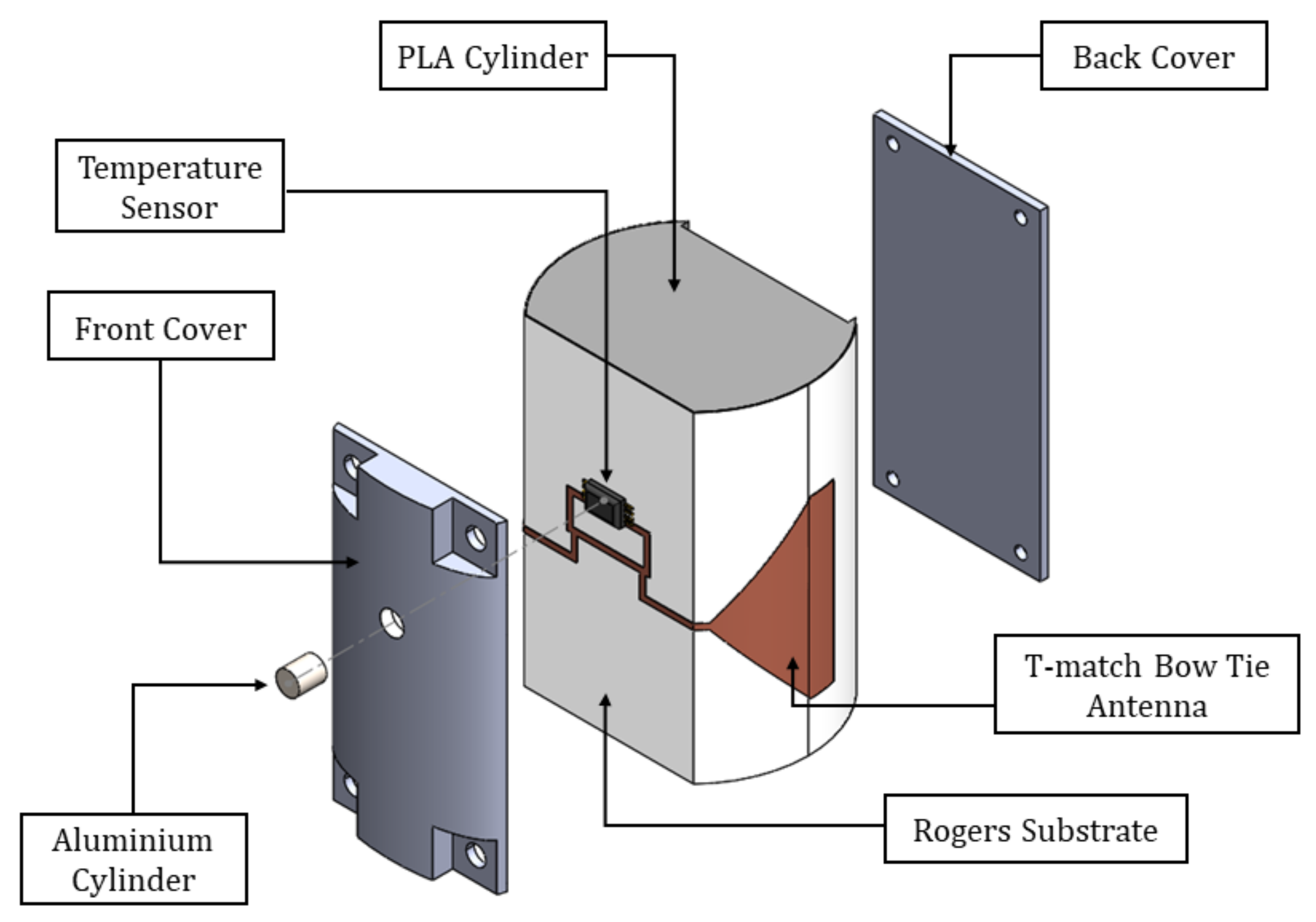
2.1. Wireless RFID Temperature Sensor
2.2. RFID Reader
2.3. Monitoring Software
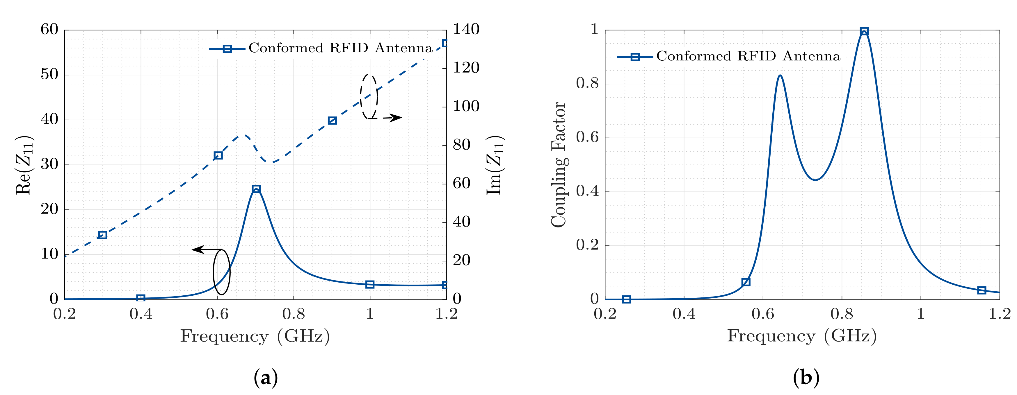
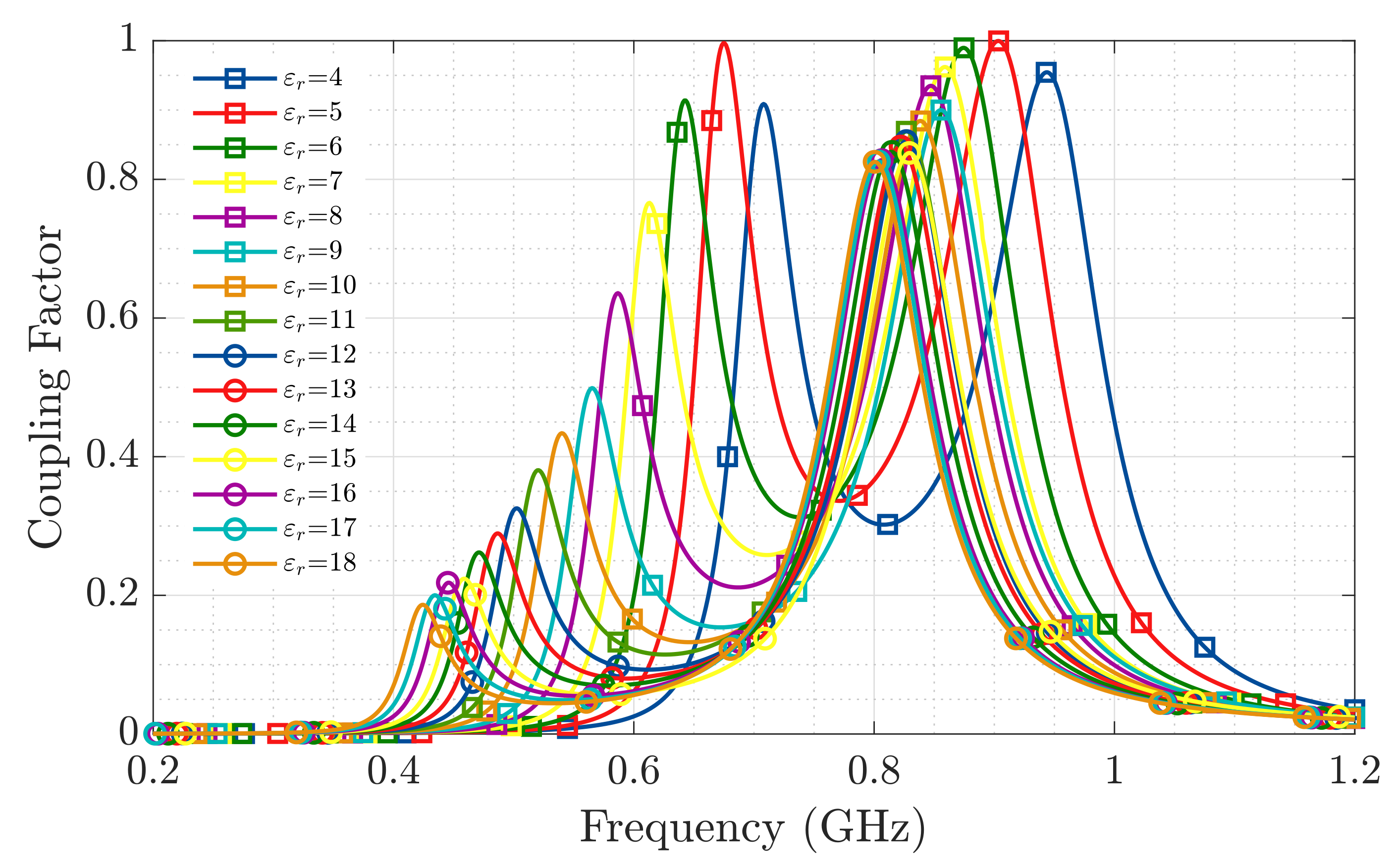
2.4. Propagation Loss between the RFID Reader and the Embedded RFID Sensor
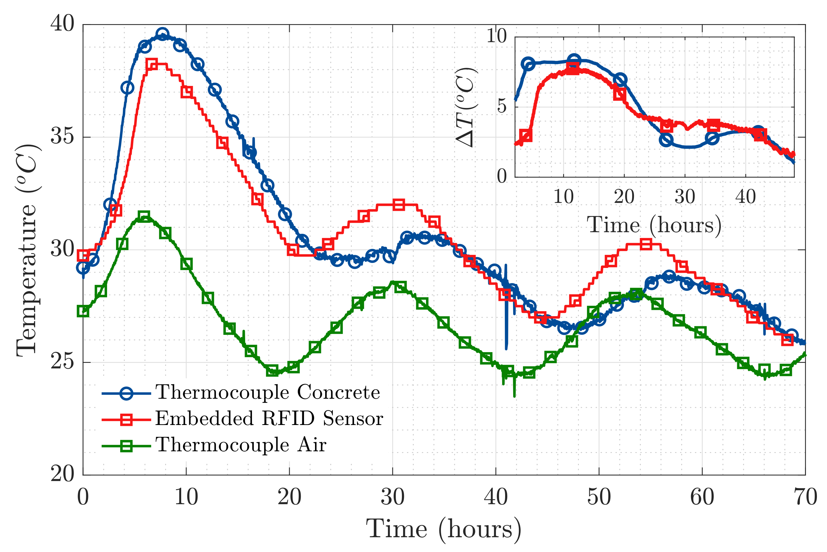
3. In-Field Measurements
4. Conclusions
5. Patents
Author Contributions
Funding
Acknowledgments
Conflicts of Interest
References
- González-López, G.; Blanch, S.; Romeu, J.; Jofre, L. Debye Frequency-Extended Waveguide Permittivity Extraction for High Complex Permittivity Materials: Concrete Setting Process Characterization. IEEE Trans. Instrum. Meas. 2019, 69, 5604–5613. [Google Scholar] [CrossRef]
- Cataldo, A.; De Benedetto, E.; Cannazza, G. Hydration Monitoring and Moisture Control of Cement-Based Samples Through Embedded Wire-Like Sensing Elements. IEEE Sens. J. 2015, 15, 1208–1215. [Google Scholar] [CrossRef]
- Zhou, S.; Sheng, W.; Deng, F.; Wu, X.; Fu, Z. A Novel Passive Wireless Sensing Method for Concrete Chloride Ion Concentration Monitoring. Sensors 2017, 17, 2817. [Google Scholar] [CrossRef] [PubMed] [Green Version]
- Zhou, S.; Deng, F.; Yu, L.; Li, B.; Wu, X.; Yin, B. A Novel Passive Wireless Sensor for Concrete Humidity Monitoring. Sensors 2016, 16, 1535. [Google Scholar] [CrossRef] [PubMed]
- Ozbey, B.; Erturk, V.B.; Demir, H.V.; Altintas, A.; Kurc, O. A Wireless Passive Sensing System for Displacement/Strain Measurement in Reinforced Concrete Members. Sensors 2016, 16, 496. [Google Scholar] [CrossRef] [PubMed] [Green Version]
- Ramos, A.; Girbau, D.; Lazaro, A.; Villarino, R. Wireless concrete mixture composition sensor based on time-coded UWB RFID. IEEE Microw. Wirel. Compon. Lett. 2015, 25, 681–683. [Google Scholar] [CrossRef]
- Jayawardana, D.; Liyanapathirana, R.; Zhu, X. RFID-Based Wireless Multi-Sensory System for Simultaneous Dynamic Acceleration and Strain Measurements of Civil Infrastructure. IEEE Sens. J. 2019, 19, 12389–12397. [Google Scholar] [CrossRef]
- Liu, Y.; Deng, F.; He, Y.; Li, B.; Liang, Z.; Zhou, S. Novel concrete temperature monitoring method based on an embedded passive RFID sensor tag. Sensors 2017, 17, 1463. [Google Scholar] [CrossRef] [PubMed] [Green Version]
- Manzari, S.; Musa, T.; Randazzo, M.; Rinaldi, Z.; Meda, A.; Marrocco, G. A passive temperature radio-sensor for concrete maturation monitoring. In Proceedings of the 2014 IEEE RFID Technology and Applications Conference (RFID-TA), Tampere, Finland, 8–9 September 2014; pp. 121–126. [Google Scholar]
- Gartner, E.; Young, J.; Damidot, D.; Jawed, I. Hydration of Portland cement. Struct. Perform. Cem. 2002, 2, 57–113. [Google Scholar]
- Narmluk, M.; Nawa, T. Effect of fly ash on the kinetics of Portland cement hydration at different curing temperatures. Cem. Concr. Res. 2011, 41, 579–589. [Google Scholar] [CrossRef] [Green Version]
- EM Microelectronic, 18000-63 Type C (Gen2) and 18000-63 Type C/18000-64 Type D (Gen2/TOTAL) RFID IC. Available online: https://www.emmicroelectronic.com/product/epc-and-uhf-ics/em4325 (accessed on 16 September 2020).
- NORDIC ID NUR-10W RFID MODULES. Available online: https://www.nordicid.com/device/modules/ (accessed on 16 September 2020).
- Balanis, C.A. Antenna Theory: Analysis and Design; John Wiley & Sons: Hoboken, NJ, USA, 2016. [Google Scholar]
- Cardama, Á.; Jofre, L.; Rius, J.M.; Romeu, J.; Blanch, S.; Ferrando, M. Antenas. Ed. UPC 2002, 8032. [Google Scholar]
- Sellés, V.; Miquel, G.L.G.; Jofre, L. Embedded Sensor Transmission Optimization with a X-Wave mini-Anechoic Chamber. In Proceedings of the 2020 XXXV Simposium Nacional de la Unión Científica Internacional de Radio (URSI Málaga, 2020), Málaga, Spain, 2–4 September 2020. [Google Scholar]
- Lin, Y.; Meng, L.; Jin, C.; Shuang, L. Design and Anti-Interference Ability Analysis of RFID Positioning System for Mine Locomotive. In Proceedings of the 2017 IEEE International Conference on Computational Intelligence and Computing Research (ICCIC), Coimbatore, India, 14–16 December 2017; pp. 1–4. [Google Scholar]
- Fu, X.; Yao, H.; Postolache, O.; Yang, Y. Message forwarding for WSN-Assisted Opportunistic Network in disaster scenarios. J. Netw. Comput. Appl. 2019, 137, 11–24. [Google Scholar] [CrossRef]
- Fu, X.; Yao, H.; Yang, Y. Cascading failures in wireless sensor networks with load redistribution of links and nodes. Ad Hoc Netw. 2019, 93, 101900. [Google Scholar] [CrossRef]
- Fu, X.; Yao, H.; Yang, Y. Modeling Cascading Failures for Wireless Sensor Networks With Node and Link Capacity. IEEE Trans. Veh. Technol. 2019, 68, 7828–7840. [Google Scholar] [CrossRef]

| Parameter | Value | Description |
|---|---|---|
| Dimensions | 41.2 mm × 30 mm | Height × Diameter of the RFID sensor. |
| Volume | 0.0172 m | Volume of the RFID sensor. |
| Weight | 23 g | Weight of the RFID sensor. |
| Temperature range | −40 C to +60 C | Temperature range of the RFID sensor. |
| Temperature Accuracy | ±1 C | Temperature accuracy of the EM4325 chip. |
| ZEM4325 | Input impedance of the EM4325 chip in BAP mode. | |
| Antenna Radiation Pattern | Dipole-like (Omnidirectional) | Shape of the Bow Tie T-match antenna radiation pattern in azimuth. |
| Device Consumption | 15.9 W | Power consumption per reading of the EM4325 RFD chip. |
| Parameter | Value | Description |
|---|---|---|
| −31 dBm | Sensitivity of the EM4325 chip. | |
| 30 dBm | Output Power of the Nordic eNUR reader. | |
| 9 dBi | Gain of the RFID Reader Antenna. | |
| 2.95 dBi | Directivity of the RFID Sensor Antenna. | |
| 0.4 | Radiation Efficiency of the RFID Sensor Antenna. | |
| 0.15 m, 0.02 m | Propagation distance inside concrete medium. | |
| 0.345 m | Wavelength in Free Space (). | |
| 3 dB | Polarization Missmatch Losses. |
| (m) | (dB/cm) | (dB) (0.15 m/0.02 m) | (dB) (0.15 m/0.02 m) | (dB) (0.15 m/0.02 m) | (dB) | ||
|---|---|---|---|---|---|---|---|
| Day 0.5 | 16.8 − j10 | 0.084 | 1.95 | 29.25/3.9 | 27.02/9.52 | 56.27/13.42 | −6.73 |
| Day 1 | 15.5 − j9.8 | 0.088 | 1.6 | 24/3.2 | 26.62/9.12 | 50.62/12.32 | −6.43 |
| Day 2 | 15 − j8.9 | 0.089 | 1.5 | 22.5/3 | 26.52/9.02 | 49.02/12.02 | −6.3 |
| Day 4 | 14.2 − j6.2 | 0.092 | 1.3 | 19.5/2.6 | 26.23/8.73 | 45.73/11.33 | −6.09 |
| Day 8 | 13.7 − j5.7 | 0.093 | 1.19 | 17.85/2.38 | 26.14/8.64 | 43.99/11.02 | −5.96 |
| (dB) @(0.15 m/0.02 m) | f = 0.43 GHz | f = 0.868 GHz | f = 2.45 GHz |
|---|---|---|---|
| Day 0.5 | 44.24/6.77 | 56.27/13.42 | 82.8/24.62 |
| Day 1 | 39.14/5.93 | 50.62/12.32 | 76.67/23.37 |
| Day 2 | 36.23/5.55 | 49.02/12.02 | 78.44/23.3 |
| Day 4 | 33.25/4.99 | 45.73/11.33 | 77.28/23 |
| Day 8 | 31.79/4.67 | 43.99/11.02 | 78.06/23.02 |
Publisher’s Note: MDPI stays neutral with regard to jurisdictional claims in published maps and institutional affiliations. |
© 2020 by the authors. Licensee MDPI, Basel, Switzerland. This article is an open access article distributed under the terms and conditions of the Creative Commons Attribution (CC BY) license (http://creativecommons.org/licenses/by/4.0/).
Share and Cite
González-López, G.; Romeu, J.; Cairó, I.; Segura, I.; Ikumi, T.; Jofre-Roca, L. Wireless Sensing of Concrete Setting Process. Sensors 2020, 20, 5965. https://doi.org/10.3390/s20205965
González-López G, Romeu J, Cairó I, Segura I, Ikumi T, Jofre-Roca L. Wireless Sensing of Concrete Setting Process. Sensors. 2020; 20(20):5965. https://doi.org/10.3390/s20205965
Chicago/Turabian StyleGonzález-López, Giselle, Jordi Romeu, Ignasi Cairó, Ignacio Segura, Tai Ikumi, and Lluis Jofre-Roca. 2020. "Wireless Sensing of Concrete Setting Process" Sensors 20, no. 20: 5965. https://doi.org/10.3390/s20205965
APA StyleGonzález-López, G., Romeu, J., Cairó, I., Segura, I., Ikumi, T., & Jofre-Roca, L. (2020). Wireless Sensing of Concrete Setting Process. Sensors, 20(20), 5965. https://doi.org/10.3390/s20205965