Ambient Backscattering-Enabled SWIPT Relaying System with a Nonlinear Energy Harvesting Model


Abstract
1. Introduction
- (i)
- We first study a wireless energy relaying system where each communication is performed in two stages: from the source to the relay and from the relay to destination. In order to deliver power and information simultaneously by the same signal, the relay is equipped with a PS mechanism to split the incoming signals in the power domain at the receiver. Besides the EH relaying, the relay also corporates with other neighboring nodes by reflecting its own information via an AmBC protocol. Motivated by the aforementioned observations, we consider two communication protocols at the relay node: the SWIPT for the primary communication and the AmBC for the secondary communication. Thus, the AmBC-enabled SWIPT relaying not only recharges the relay nodes via SWIPT, but also offers low power communication via AmBC without any extra infrastructure. We also provide details about system features along with data transmission procedures.
- (ii)
- Next, we present a nonlinear EH model that is commonly used in energy harvesting applications. This reflects the characteristics of an EH circuit in converting the input RF power to the output direct current (DC) power for use. Under this EH model, we derive upper bounds of outage probabilities in both primary and secondary communication links, where the end-to-end transmission signal-to-noise ratio (SNR) must be larger than or equal to the required SNR threshold. Moreover, since the system adopts the PS scheme at the relay, the PS ratio is dynamically adjusted according to the channel gain at a certain communication time.
- (iii)
- Finally, the performance of the system is analyzed through several simulation results. We show both outage probability and achievable throughput in terms of transmit power and transmission rate. We also derive energy efficiency of the proposed scheme with a nonlinear EH model and compare to the conventional one with a linear EH model [11].
2. Background and Motivation
2.1. Energy Harvesting Relaying
2.2. Ambient Backscatter-Enabled Relaying with SWIPT
2.3. Motivation
3. System Description
3.1. System Components
- (A1)
- R is able to dynamically collaborative data transmission and energy harvesting by the antenna selection schemes.
- (A2)
- R uses DF relaying with PS strategy with the same codebook as that of the source S, where the receiver structure for splitting information and energy at R is depicted in Figure 1b.
3.2. Cooperative Transmission Strategy
3.2.1. Phase I-Transmission
- Part of is received at the relay for information delivery. Denoting the signal is delivered to the ID circuit at R as and its corresponding SNR during the first transmission phase as , we have:
- Another part of is harvested by the relay. The amount of harvested energy during this phase is defined by:
3.2.2. Phase II-Transmission
4. Performance Analysis
4.1. Theory of Nonlinear Energy Harvesting
4.2. Adaptive PS Ratio and Distance Optimization
4.3. Outage Probability for the Primary Communication Link
4.4. Outage Probability for the Secondary Communication Link
4.4.1. On R→C Link during the First Transmission Phase
4.4.2. On C→R Link during the Second Transmission Phase
5. Simulation Results
- (i)
- In the context of the PS ratio discussed in Section 4.2, we keep a fixed transmit power and calculate the average optimal PS ratio by Equation (24) over a certain number of channel realizations. The relationship between and is graphically described in Figure 2.
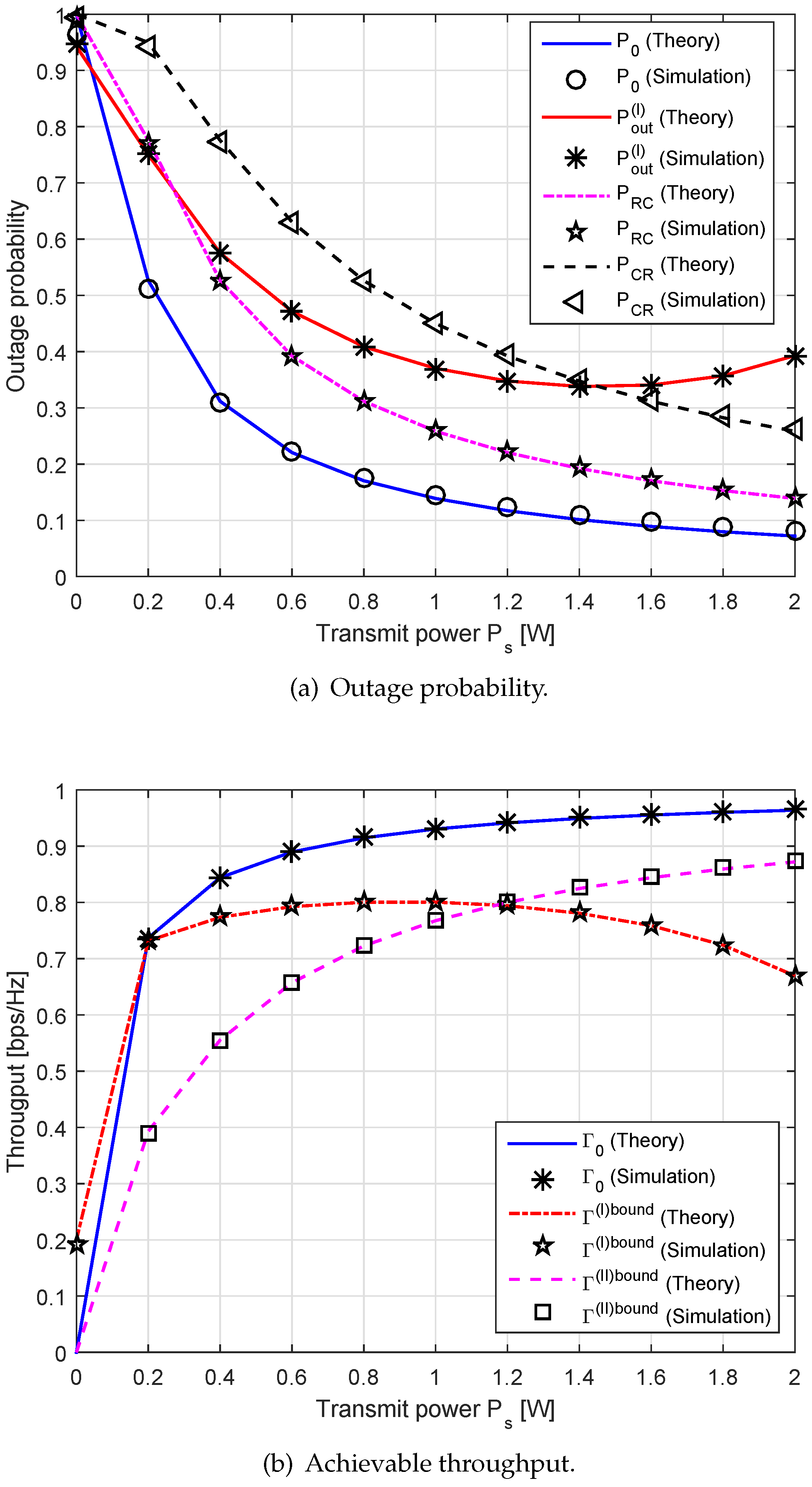
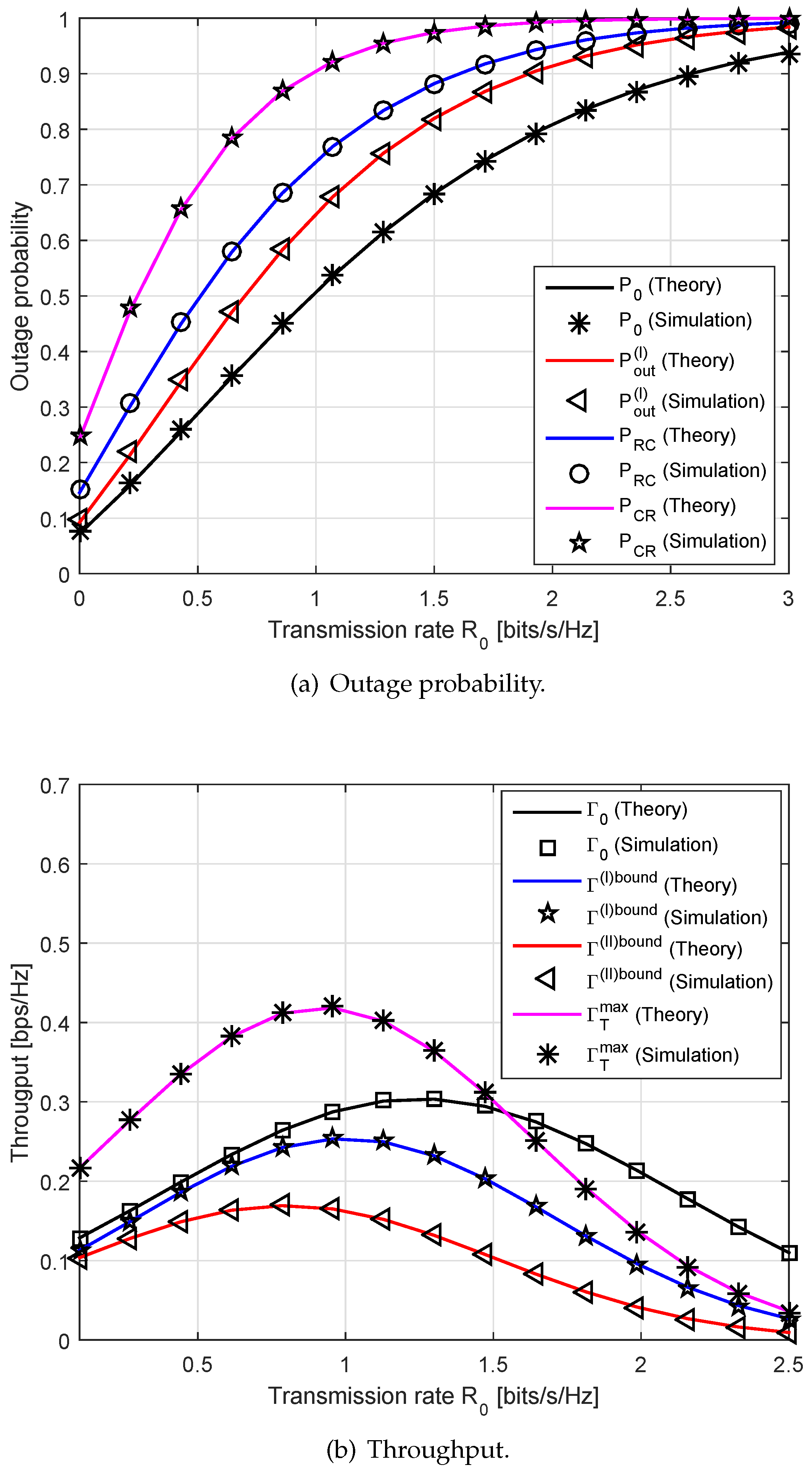
- (ii)
- Next, we investigate the impact of transmission-related parameters (e.g., transmission rates and , distance between two receivers , transmit power ) on the outage probability and the achievable throughput. In the simulations, we depict the theory and the simulation results in the same plot, where the theory is depicted by a straight line and the simulation by bullet symbols.
- (iii)
- We compare the energy efficiency of the conventional [11] and the proposed schemes. We also denote and as the energy efficiency of the system with the linear and the nonlinear EH models, respectively. For a comparison purpose, we set for the conventional scheme, while it was given as Equation (16) for our proposed scheme.
6. Conclusions
Author Contributions
Funding
Conflicts of Interest
Abbreviations
| AmBC | Ambient backscatter communication |
| AF | Amplify-and-forward |
| BC | backscatter communication |
| CDF | Cumulative distribution function |
| DC | Direct current |
| DF | Decode-and-forward |
| EH | Energy harvesting |
| ID | Information decoding |
| IoT | Internet of things |
| Probability density function | |
| PS | Power splitting |
| RF | Radio frequency |
| RFID | Radio frequency identification |
| SINR | Signal-to-interference-plus-noise ratio |
| SNR | Signal-to-noise ratio |
| SWIPT | Simultaneous information and power transfer |
| TS | Time switching |
References
- Guo, J.; Zhu, X. An improved analytical model for RF-DC conversion efficiency in microwave rectifiers. In Proceedings of the 2012 IEEE MTT-S International Microwave Symposium, Montreal, QC, Canada, 17–22 June 2012; pp. 1–3. [Google Scholar]
- Lu, X.; Wang, P.; Niyato, D.; Kim, D.I.; Han, Z. Wireless networks with RF energy harvesting: A contemporary survey. IEEE Commun. Surv. Tutor. 2015, 17, 757–789. [Google Scholar] [CrossRef]
- Valenta, C.; Durgin, G. Harvesting wireless power: Survey of energy-harvester conversion efficiency in far-field, wireless power transfer systems. IEEE Microw. Mag. 2014, 15, 108–120. [Google Scholar]
- Xu, C.; Yang, L.; Zhang, P. Practical backscatter communication system for battery-free Internet of Things: A tutorial and survey of recent research. IEEE Signal Proc. Mag. 2018, 35, 16–27. [Google Scholar] [CrossRef]
- Darsena, D.; Gelli, G.; Verde, F. Modeling and performance analysis of wireless networks with ambient backscatter devices. IEEE Trans. Commun. 2017, 65, 1797–1814. [Google Scholar] [CrossRef]
- Jia, X.; Zhou, X. Performance characterization of relaying using backscatter devices. IEEE Open J. Commun. Soc. 2020, 1, 819–834. [Google Scholar] [CrossRef]
- Ding, H.; Costa, D.B.; Ge, J. Outage analysis for cooperative ambient backscatter systems. IEEE Wirel. Commun. Lett. 2019, 9, 601–605. [Google Scholar] [CrossRef]
- Jabbar, H.; Song, Y.S.; Jeong, T.T. RF energy harvesting system and circuits for charging of mobile devices. IEEE Trans. Consum. Electron. 2010, 56, 247–253. [Google Scholar] [CrossRef]
- Krikidis, I.; Timotheou, S.; Nikolaou, S.; Zheng, G.; Ng, D.W.K.; Schober, R. Simultaneous wireless information and power transfer in modern communication systems. IEEE Commun. Mag. 2014, 52, 104–110. [Google Scholar] [CrossRef]
- Nasir, A.A.; Zhou, X.; Durrani, S.; Kennedy, R.A. Relaying protocols for wireless energy harvesting and information processing. IEEE Trans. Wirel. Commun. 2013, 12, 3622–3636. [Google Scholar] [CrossRef]
- Shah, S.T.; Choi, K.W.; Lee, T.J.; Chung, M.Y. Outage probability and throughput analysis of SWIPT enabled cognitive relay network with ambient backscatter. IEEE Internet Things 2018, 5, 3198–3207. [Google Scholar]
- Nguyen, T.L.N.; Shin, Y. Outage probability analysis for SWIPT systems with nonlinear energy harvesting model. In Proceedings of the 2019 International Conference on Information and Communication Technology Convergence (ICTC 2019), Jeju, Korea, 16–18 October 2019; pp. 196–199. [Google Scholar]
- Alevizos, P.N.; Vougioukas, G.; Bletsas, A. Nonlinear energy harvesting models in wireless information and power transfer. In Proceedings of the 19th IEEE International Workshop on Signal Processing Advances in Wireless Communications (SPAWC 2018), Kalamata, Greece, June 25–28 August 2018; pp. 1–5. [Google Scholar]
- Pinuela, M.; Mitcheson, P.D.; Lucyszyn, S. Ambient RF energy harvesting in urban and semi-urban environments. IEEE Trans. Microw. Theory Tech. 2013, 61, 2715–2726. [Google Scholar] [CrossRef]
- Hwang, D.; Hwang, K.C.; Kim, D.I.; Lee, T.-J. Self-energy recycling for RF powered multi-antenna relay channels. IEEE Trans. Wirel. Commun. 2017, 16, 812–824. [Google Scholar] [CrossRef]
- Zeng, Y.; Zhang, R. Full-duplex wireless-powered relay with self-energy recycling. IEEE Wirel. Commun. Lett. 2015, 4, 201–204. [Google Scholar] [CrossRef]
- Riihonen, T.; Werner, S.; Wichman, R. Mitigation of loop-back self-interference in full-duplex MIMO relays. IEEE Trans. Signal Proc. 2011, 59, 5983–5993. [Google Scholar] [CrossRef]
- Li, T.; Fan, P.; Letaief, K.B. Outage probability of energy harvesting relay-aided cooperative networks over Rayleigh fading channel. IEEE Trans. Veh. Technol. 2016, 65, 972–978. [Google Scholar] [CrossRef]
- Cao, H.; Fu, L.; Dai, H. Throughput analysis of the two-way relay system with network coding and energy harvesting. In Proceedings of the IEEE International Conference on Communications (ICC 2017), Paris, France, 21–25 May 2017; pp. 1–6. [Google Scholar]
- Feng, Y.; Wen, M.; Ji, F.; Leung, V.C.M. Performance analysis for BDPSK modulated SWIPT cooperative systems with nonlinear energy harvesting model. IEEE Access 2018, 6, 42373–42383. [Google Scholar] [CrossRef]
- Cheon, S.; Kang, S.Y.; Lee, M.L.; Lee, J.M.; Zyung, T.Y. Circuit-model-based analysis of a wireless energy-transfer system via coupled magnetic resonances. IEEE Trans. Ind. Electr. 2011, 58, 2906–2914. [Google Scholar] [CrossRef]
- Kiani, M.; Ghovanloo, M. The circuit theory behind coupled-mode magnetic resonance-based wireless power transmission. IEEE Trans. Circuits Syst. 2012, 59, 2065–20742. [Google Scholar] [CrossRef]
- Wang, C.-S.; Covic, G.A.; Stielau, O.H. Power transfer capability and bifurcation phenomena of loosely coupled inductive power transfer systems. IEEE Trans. Ind. Electr. 2004, 51, 148–157. [Google Scholar] [CrossRef]
- Hui, S.Y.R.; Zhong, W.; Lee, C. A critical review of recent progress in mid-range wireless power transfer. IEEE Trans. Power Electr. 2013, 29, 4500–4511. [Google Scholar] [CrossRef]
- Boshkovska, E.; Ng, D.W.K.; Zlatanov, N.; Schober, R. Practical non-linear energy harvesting model and resource allocation for SWIPT systems. IEEE Commun. Lett. 2015, 19, 2082–2085. [Google Scholar] [CrossRef]
- Nguyen, T.L.N.; Shin, Y. Performance analysis for energy harvesting based wireless relay systems. In Proceedings of the 2019 IEEE VTS Asia Pacific Wireless Communications Symposium (APWCS), Singapore, 28–30 August 2019; pp. 1–5. [Google Scholar]
- Ashraf, M.; Jang, J.; Han, J.; Lee, K.G. Capacity maximizing adaptive power splitting protocol for cooperative energy harvesting communication systems. IEEE Commun. Lett. 2018, 22, 902–905. [Google Scholar] [CrossRef]
- Gradshteyn, I.S.; Ryzhik, I.M. Table of Integrals, Series and Products, 6th ed.; Academic Press: Cambridge, MA, USA, 2000. [Google Scholar]
- Chen, Y.; Sabnis, K.T.; Abd-Alhameed, R.A. New formula for conversion efficiency of RF-EH and its wireless applications. IEEE Trans. Veh. Technol. 2016, 65, 9410–9414. [Google Scholar] [CrossRef]
- Zhang, J.; Pan, G.; Xie, Y. Secrecy analysis of wireless-powered multi-antenna relaying system with nonlinear energy harvesters and imperfect CSI. IEEE Trans. Green Commun. Netw. 2018, 2, 460–470. [Google Scholar] [CrossRef]
- Gurjar, D.S.; Nguyen, H.H.; Pattanayak, P. Performance of wireless powered cognitive radio sensor networks with nonlinear energy harvester. IEEE Sensors Lett. 2019, 3, 1–4. [Google Scholar] [CrossRef]
- Liu, H.; Kim, K.J.; Kwak, K.S.; Poor, H.V. Power splitting-based SWIPT with decode-and-forward full-duplex relaying. IEEE Trans. Wirel. Commun. 2016, 15, 7561–7577. [Google Scholar] [CrossRef]
- Ding, Z.; Perlaza, S.M.; Esnaola, I.; Poor, H.V. Power allocation strategies in energy harvesting wireless cooperative networks. IEEE Trans. Wirel. Commun. 2014, 13, 846–860. [Google Scholar] [CrossRef]


| Notation | Definition |
|---|---|
| S, D, R, C | Primary source, destination, relay, second backscatter nodes, respectively |
| Amount of harvested energy at the relay | |
| and | Mean and variance of a random variable X |
| Probability of a parameter based on a particular dataset | |
| and | PDF and CDF of a random variable X, respectively |
| Normal distribution with mean and variance | |
| Random variable X follows with the PDF | |
| Rayleigh distribution with rate parameter | |
| X follows a Rayleigh distribution with the PDF | |
| Dirac delta function |
© 2020 by the authors. Licensee MDPI, Basel, Switzerland. This article is an open access article distributed under the terms and conditions of the Creative Commons Attribution (CC BY) license (http://creativecommons.org/licenses/by/4.0/).
Share and Cite
Nguyen, T.L.N.; Kim, J.-Y.; Shin, Y. Ambient Backscattering-Enabled SWIPT Relaying System with a Nonlinear Energy Harvesting Model. Sensors 2020, 20, 4534. https://doi.org/10.3390/s20164534
Nguyen TLN, Kim J-Y, Shin Y. Ambient Backscattering-Enabled SWIPT Relaying System with a Nonlinear Energy Harvesting Model. Sensors. 2020; 20(16):4534. https://doi.org/10.3390/s20164534
Chicago/Turabian StyleNguyen, Thu L. N., Jin-Young Kim, and Yoan Shin. 2020. "Ambient Backscattering-Enabled SWIPT Relaying System with a Nonlinear Energy Harvesting Model" Sensors 20, no. 16: 4534. https://doi.org/10.3390/s20164534
APA StyleNguyen, T. L. N., Kim, J.-Y., & Shin, Y. (2020). Ambient Backscattering-Enabled SWIPT Relaying System with a Nonlinear Energy Harvesting Model. Sensors, 20(16), 4534. https://doi.org/10.3390/s20164534