Toward Accurate Position Estimation Using Learning to Prediction Algorithm in Indoor Navigation


Abstract
1. Introduction
- The main objective of the proposed system is to get an accurate position estimation by minimizing the error in IMU sensor readings using the prediction algorithm.
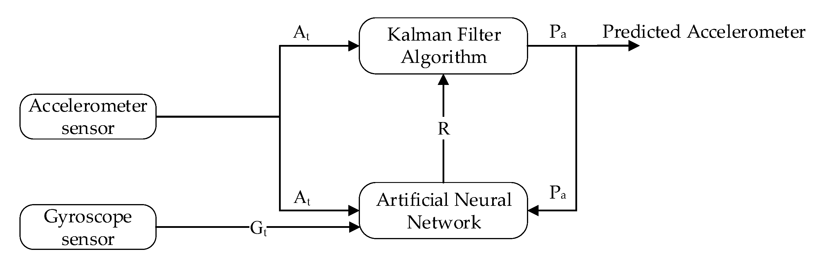
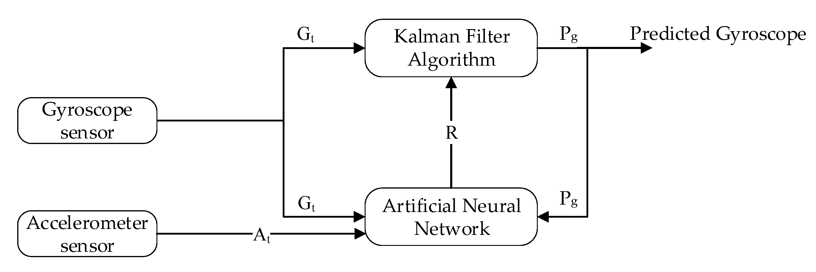
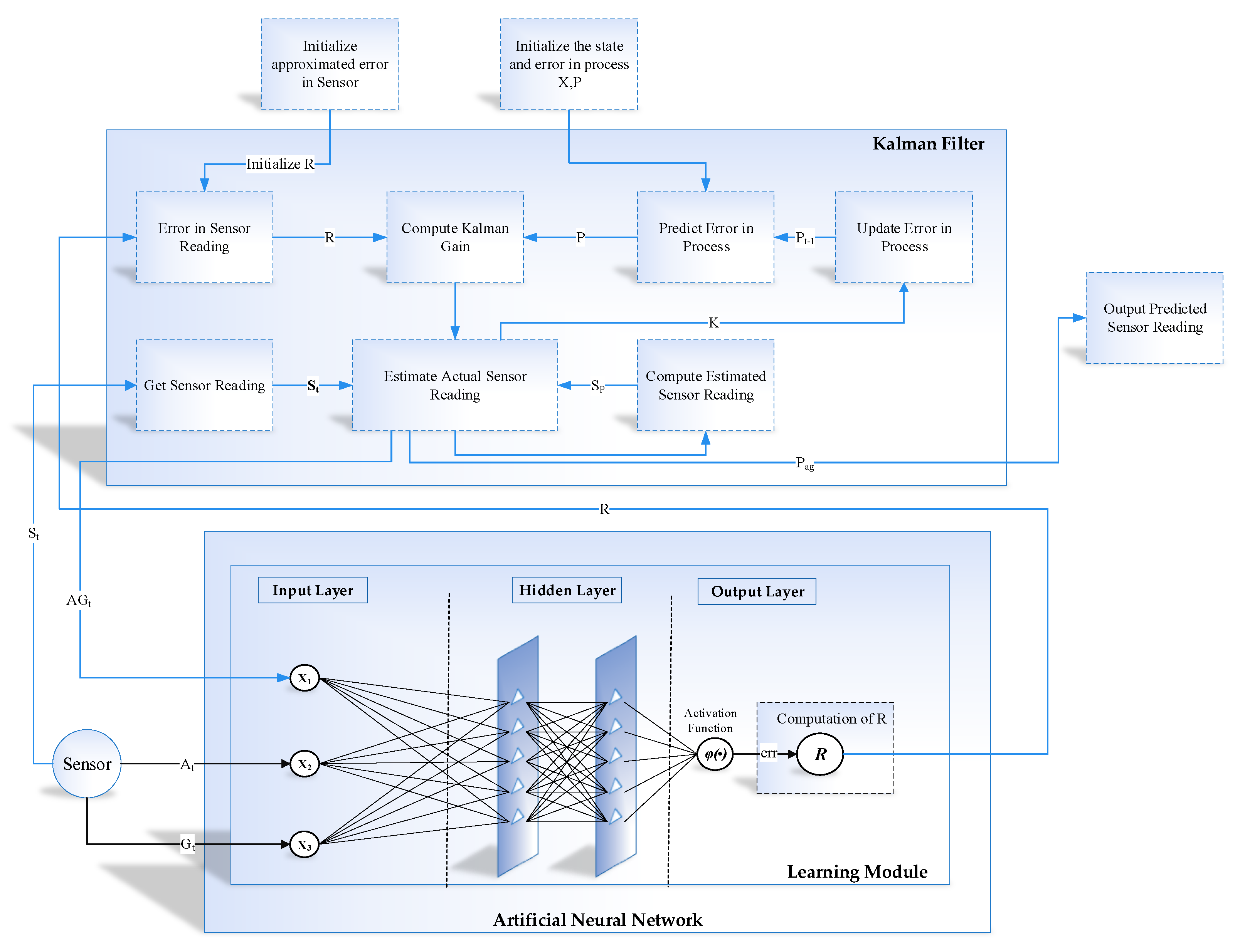
- The learning module is based on Artificial Neural Network, and Kalman filter are used as a prediction algorithm to predict the actual accelerometer and gyroscope reading from the noisy sensor reading.
- The learning module continuously controls, observes, and enhances the efficiency of the prediction algorithm by evaluating the output and taking into account the exogenous factors that may have an impact on its outcome.
- In position estimation module, the Kalman filter is used to fuse the IMU data to get noise and drift-free position in an indoor environment.
- Finally, for evaluating system performance, we analyzed the results using the well-known statistical measures such as RMSE, MAD, and MSE. Our proposed system experiments indicate that learning to prediction algorithm improves the system accuracy as compared to tradition prediction algorithm.
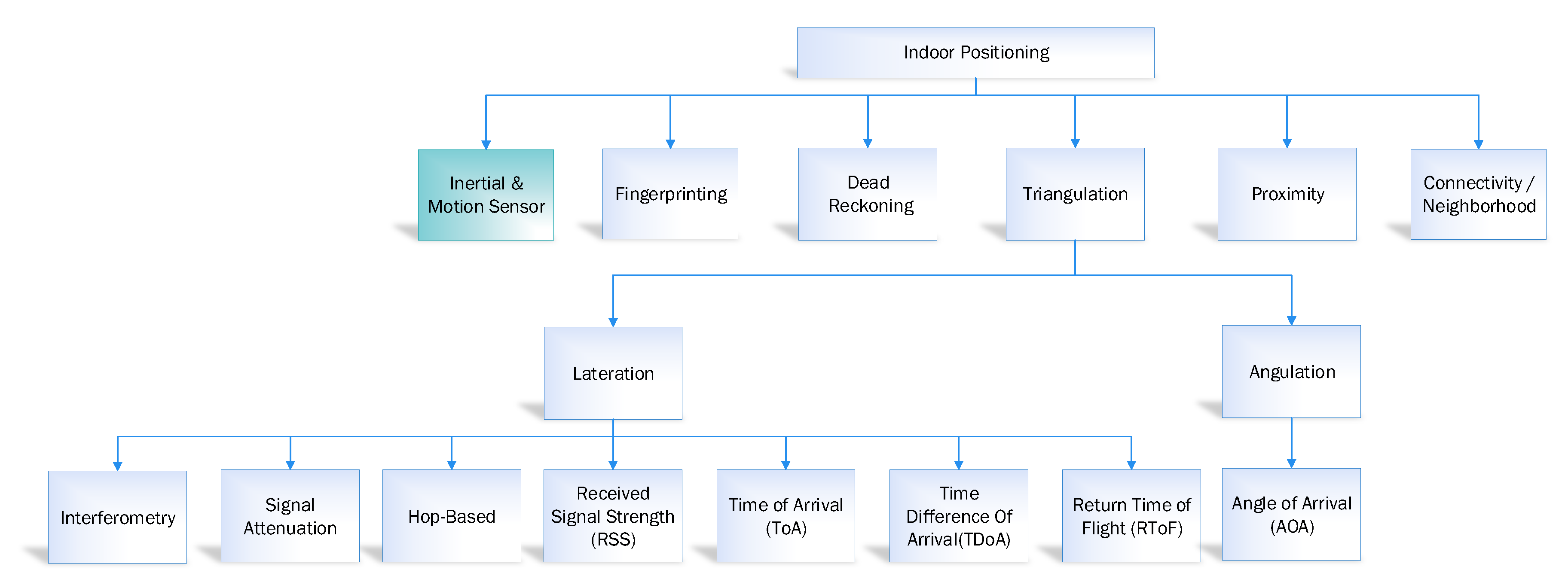
2. Related Work
2.1. Inertial and Motion Sensor
2.2. Connectivity/Neighborhood
2.3. Proximity
2.4. Triangulation
2.5. Dead Reckoning
2.6. Fingerprinting
2.7. Navigation using Machine Learning Approaches
3. Proposed Methodology
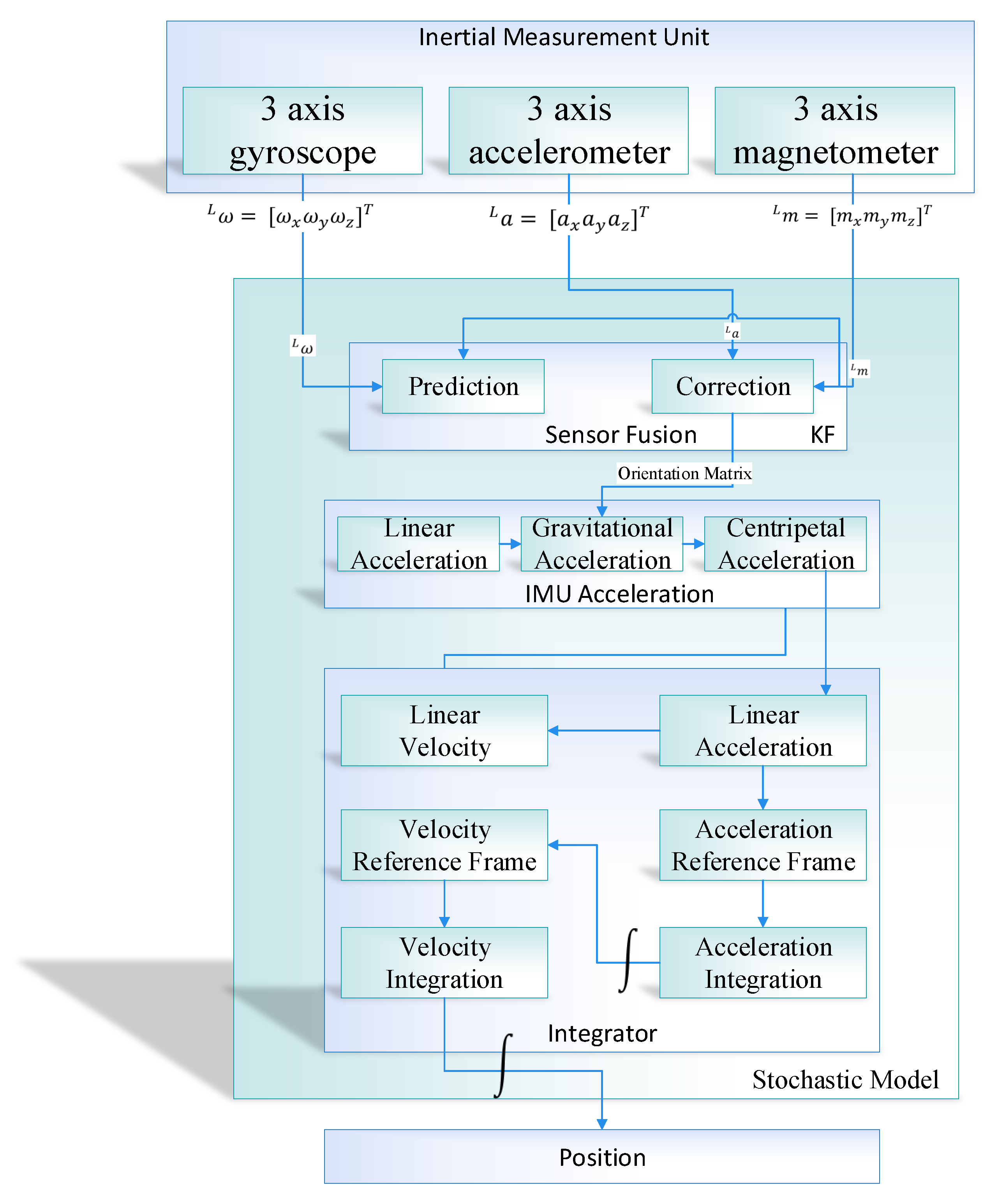
3.1. Scenario of Position Estimation in Indoor Navigation
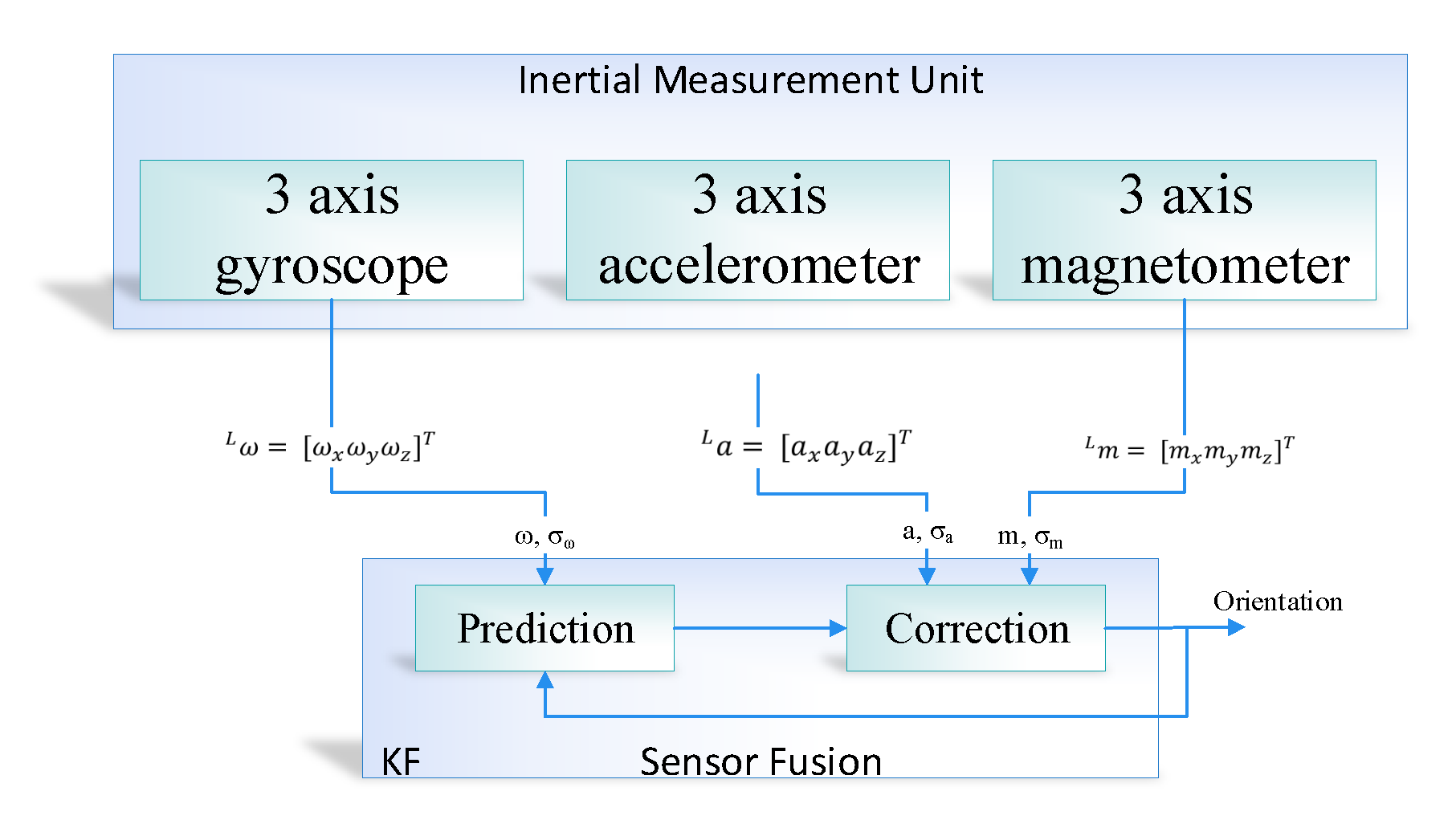
3.1.1. Sensor Fusion Using Kalman Filter
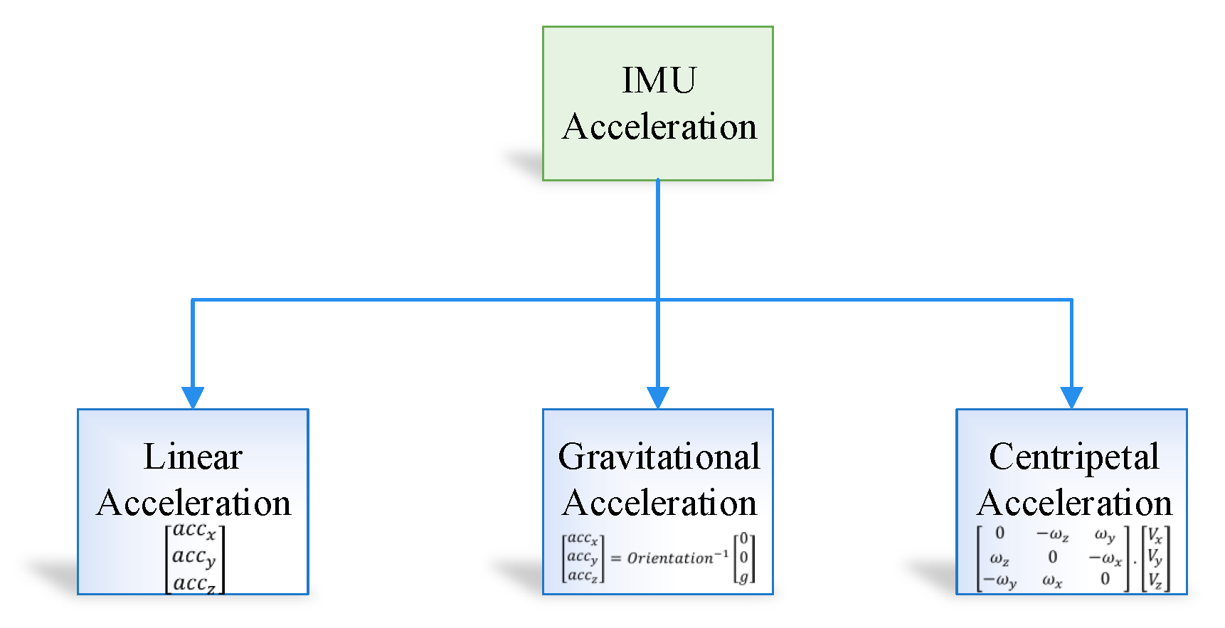
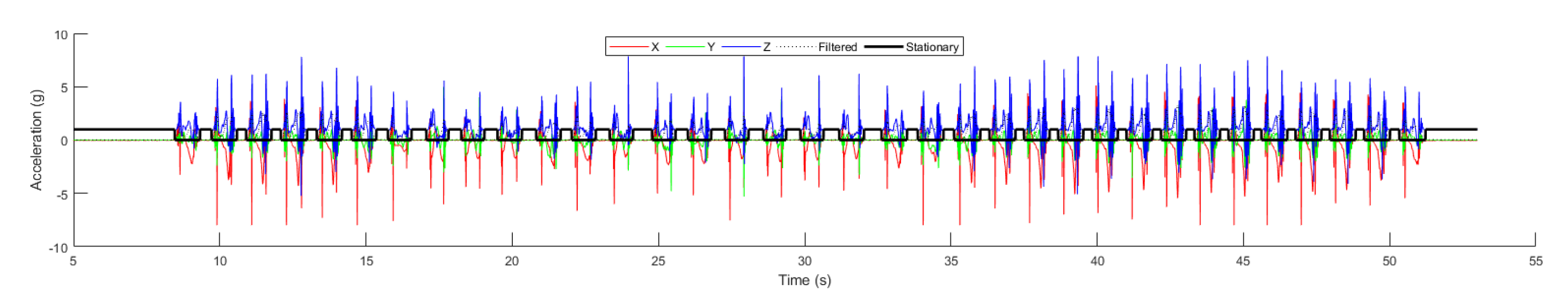
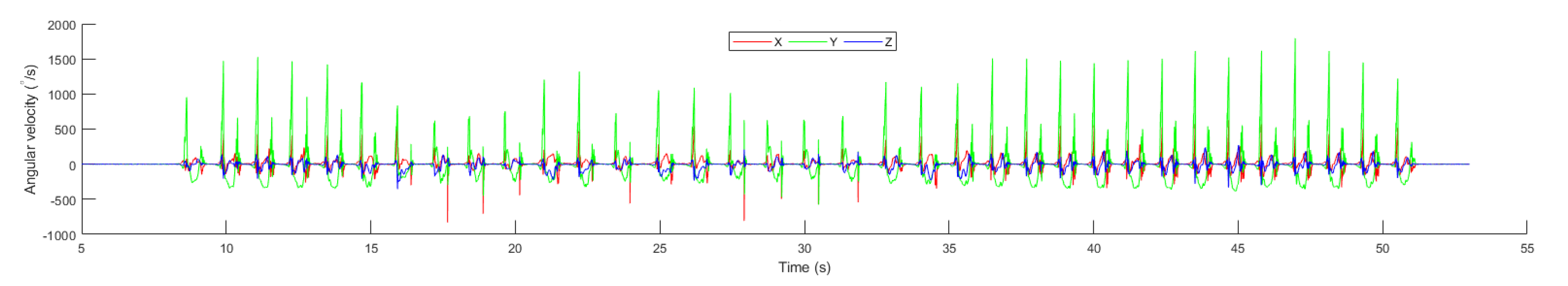
3.1.2. IMU Acceleration
3.1.3. Integrator Module
3.2. Learning to Prediction Model
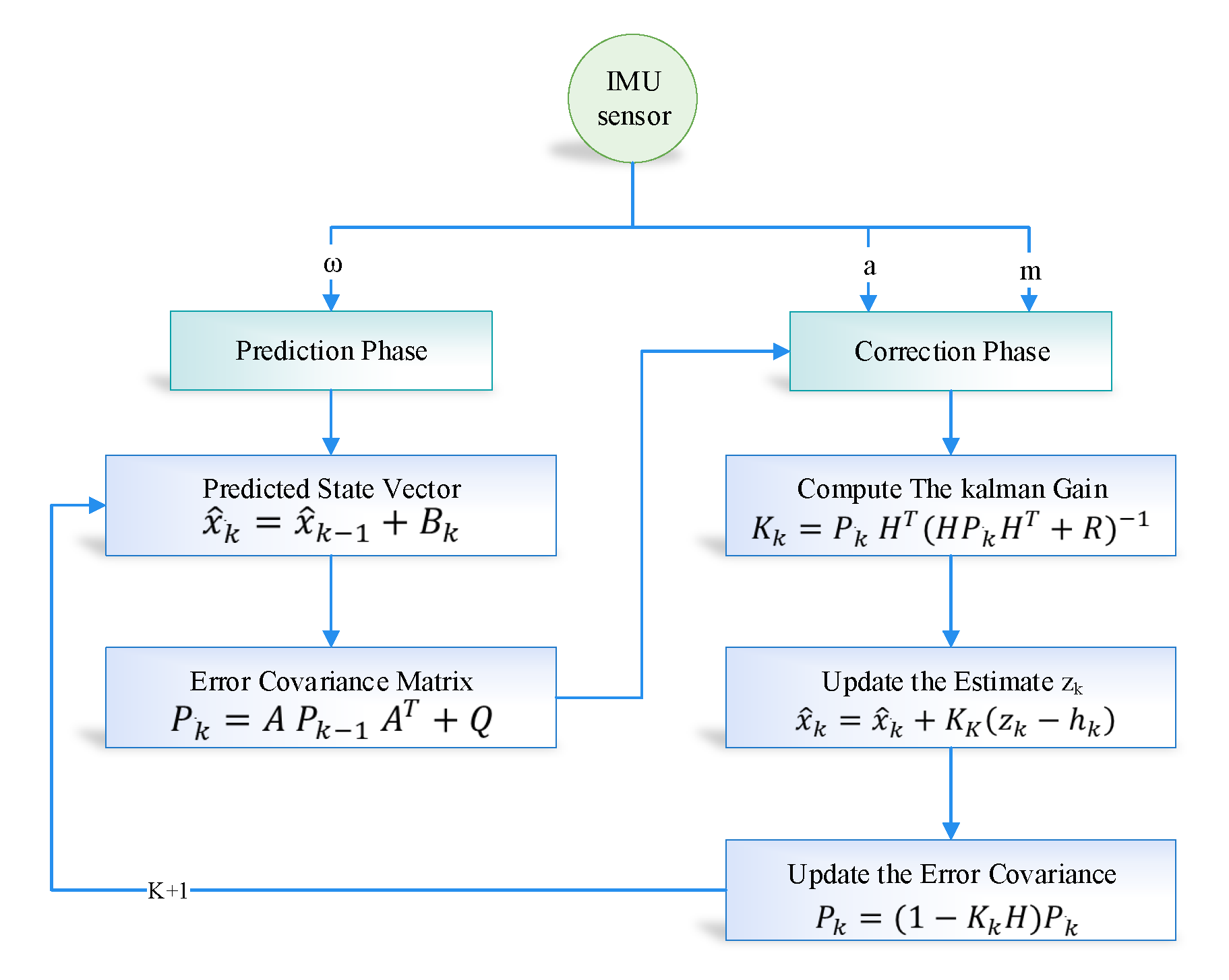
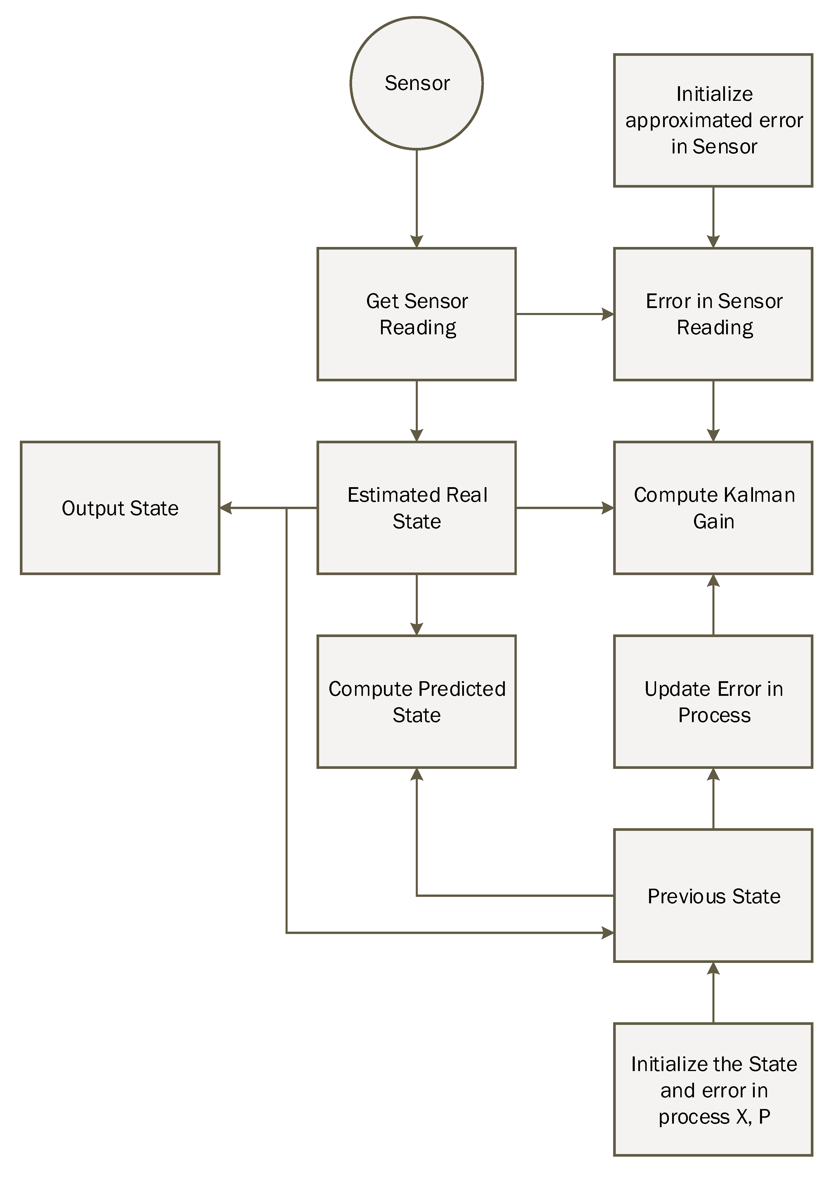
3.3. Kalman Filter Algorithm
3.4. ANN-Based Learning to Prediction for Kalman Filter
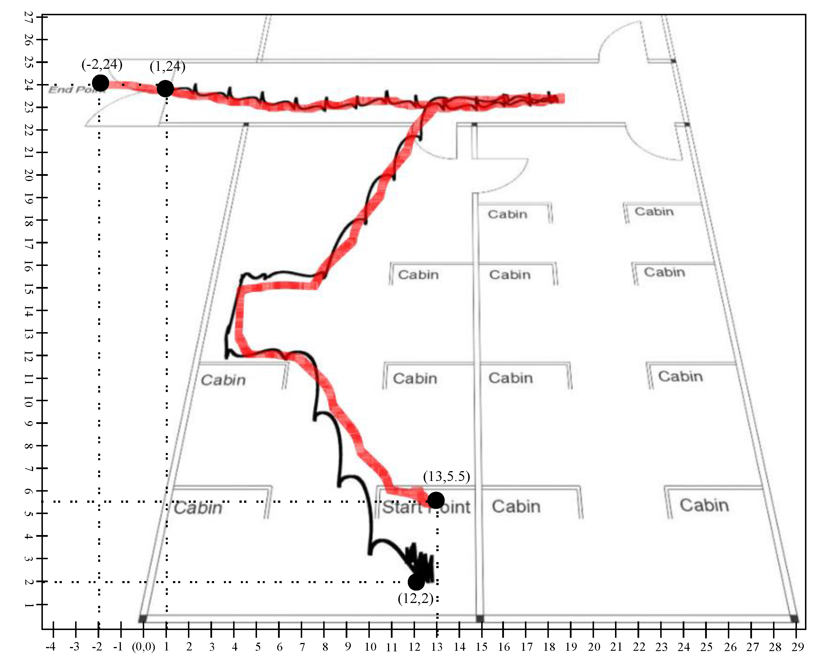
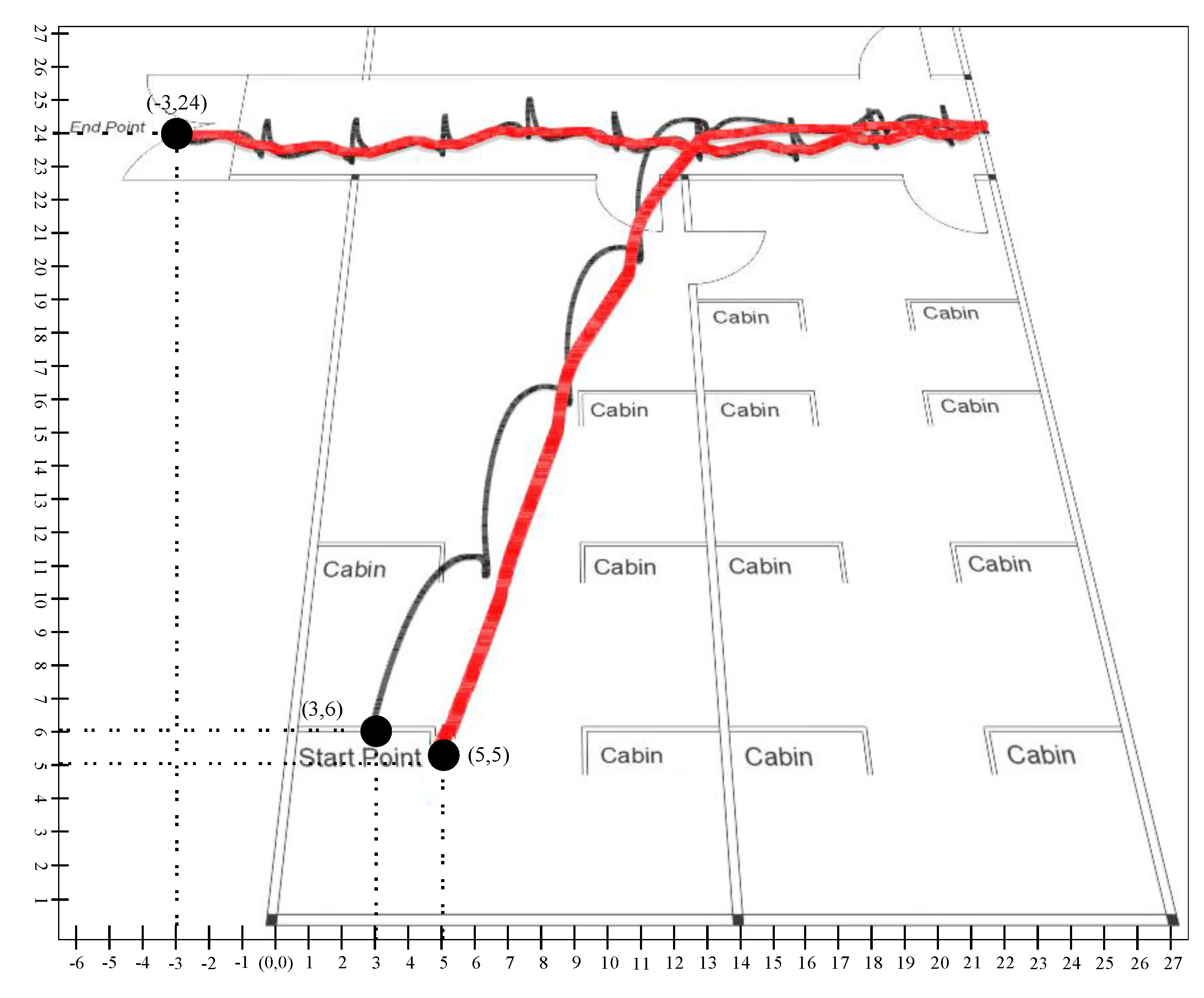
4. Experimental Results and Discussion
4.1. Development Environment
4.2. Implementation
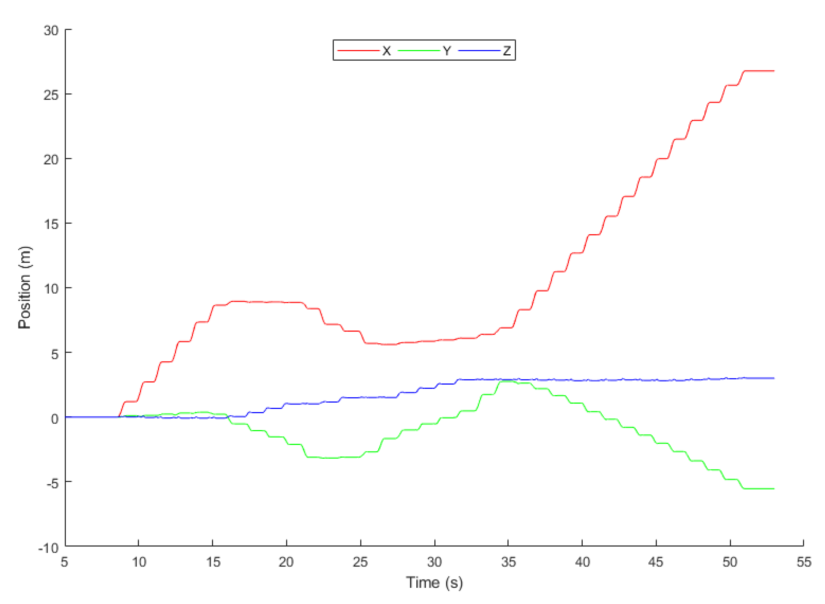
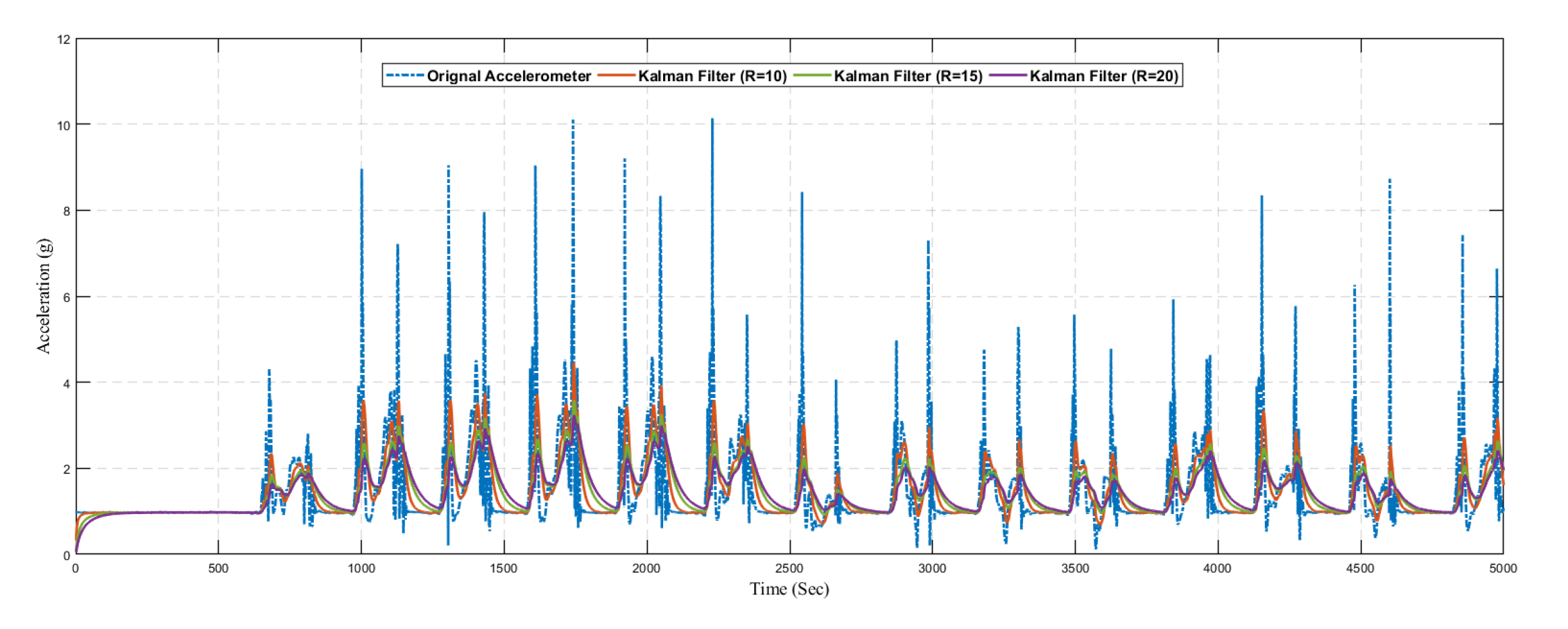
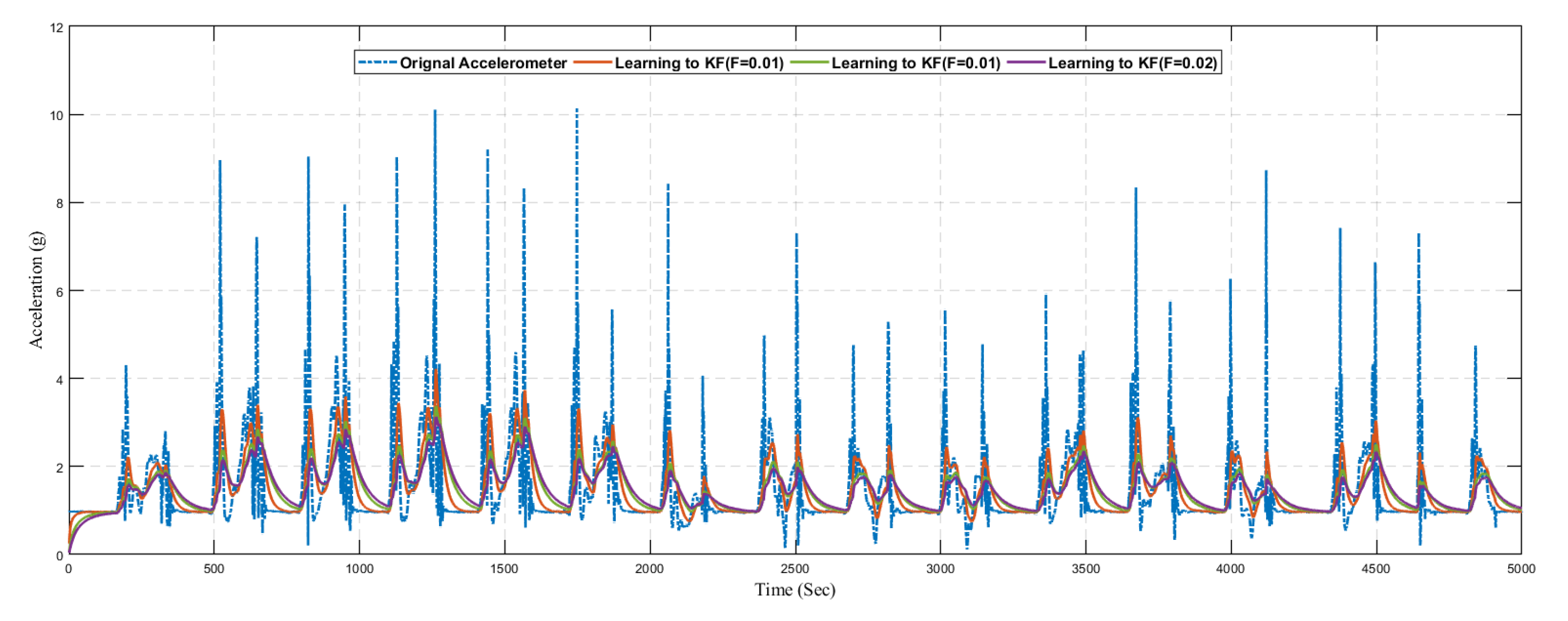
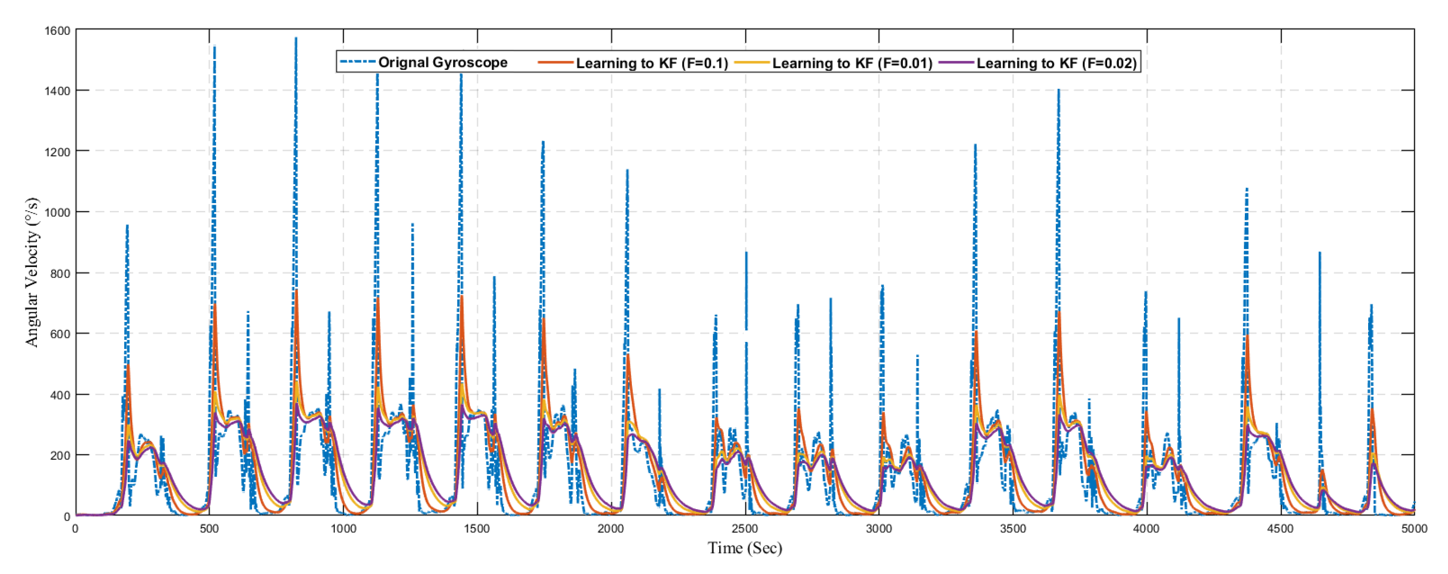
4.3. Results and Discussion
5. Conclusions and Future Work
Author Contributions
Funding
Conflicts of Interest
References
- Harle, R. A survey of indoor inertial positioning systems for pedestrians. IEEE Commun. Surv. Tutor. 2013, 15, 1281–1293. [Google Scholar] [CrossRef]
- Virrantaus, K.; Markkula, J.; Garmash, A.; Terziyan, V.; Veijalainen, J.; Katanosov, A.; Tirri, H. Developing GIS-supported location-based services. In Proceedings of the Second International Conference on Web Information Systems Engineering, Kyoto, Japan, 3–6 December 2001; pp. 66–75. [Google Scholar]
- Grewal, M.S.; Weill, L.R.; Andrews, A.P. Global Positioning Systems, Inertial Navigation, and Integration. Available online: https://onlinelibrary.wiley.com/doi/book/10.1002/0470099720 (accessed on 6 August 2020).
- Bill, R.; Cap, C.; Kofahl, M.; Mundt, T. Indoor and outdoor positioning in mobile environments a review and some investigations on wlan positioning. Geogr. Inf. Sci. 2004, 10, 91–98. [Google Scholar]
- Wu, C.; Yang, Z.; Liu, Y. Wireless Indoor Localization. IEEE Trans. Parallel Distrib. Syst. 2012, 24, 839–848. [Google Scholar]
- Bulusu, N.; Heidemann, J.; Estrin, D. GPS-less low-cost outdoor localization for very small devices. IEEE Pers. Commun. 2000, 7, 28–34. [Google Scholar] [CrossRef]
- Liu, H.; Darabi, H.; Banerjee, P.; Liu, J. Survey of wireless indoor positioning techniques and systems. IEEE Trans. Syst. Man Cybern. Part C Appl. Rev. 2007, 37, 1067–1080. [Google Scholar] [CrossRef]
- Al Nuaimi, K.; Kamel, H. A survey of indoor positioning systems and algorithms. In Proceedings of the 2011 International Conference on Innovations in Information Technology, Abu Dhabi, UAE, 25–27 April 2011; pp. 185–190. [Google Scholar]
- Collin, J.; Davidson, P.; Kirkko-Jaakkola, M.; Leppäkoski, H. Inertial Sensors and Their Applications. Available online: https://link.springer.com/book/10.1007/978-3-319-91734-4 (accessed on 6 August 2020).
- Emil, Š.; Elena, P.; Ladislav, K. Design of an Inertial Measuring Unit for Control of Robotic Devices. Mater. Sci. Forum 2019, 952, 313–322. [Google Scholar]
- Jamil, F.; Kim, D.H. Improving Accuracy of the Alpha–Beta Filter Algorithm Using an ANN-Based Learning Mechanism in Indoor Navigation System. Sensors 2019, 19, 3946. [Google Scholar] [CrossRef]
- Zhang, S. Exploring IMU Attitude and Position Estimation for Improved Location in Indoor Environments. Master’s Thesis, Oregon State University, Corvallis, OR, USA, 12 June 2019. [Google Scholar]
- Witt, C.; Bux, M.; Gusew, W.; Leser, U. Predictive performance modeling for distributed batch processing using black box monitoring and machine learning. Inf. Syst. 2019, 82, 33–52. [Google Scholar] [CrossRef]
- Lewandowicz, E.; Lisowski, P.; Flisek, P. A Modified Methodology for Generating Indoor Navigation Models. ISPRS Int. J. Geo. Inf. 2019, 8, 60. [Google Scholar] [CrossRef]
- Mortari, F.; Clementini, E.; Zlatanova, S.; Liu, L. An indoor navigation model and its network extraction. Appl. Geomat. 2019, 11, 413–427. [Google Scholar] [CrossRef]
- Gu, Y.; Lo, A.; Niemegeers, I. A survey of indoor positioning systems for wireless personal networks. IEEE Commun. Surv. Tutor. 2009, 11, 13–32. [Google Scholar] [CrossRef]
- Fuchs, C.; Aschenbruck, N.; Martini, P.; Wieneke, M. Indoor tracking for mission critical scenarios: A survey. Pervasive Mob. Comput. 2011, 7, 1–15. [Google Scholar] [CrossRef]
- Yuan, Q.; Asadi, E.; Lu, Q.; Yang, G.; Chen, I.M. Uncertainty-Based IMU Orientation Tracking Algorithm for Dynamic Motions. IEEE/ASME Trans. Mechatron. 2019, 24, 872–882. [Google Scholar] [CrossRef]
- Shen, S.; Gowda, M.; Roy Choudhury, R. Closing the gaps in inertial motion tracking. In Proceedings of the 24th Annual International Conference on Mobile Computing and Networking, New Delhi, India, 29 October–2 November 2018; pp. 429–444. [Google Scholar]
- Tejmlova, L.; Sebesta, J.; Zelina, P. Artificial neural networks in an inertial measurement unit. In Proceedings of the 2016 26th International Conference Radioelektronika (RADIOELEKTRONIKA), Kosice, Slovakia, 19–20 April 2016; pp. 176–180. [Google Scholar]
- Ding, M.; Wang, Q. An integrated navigation system of NGIMU/GPS using a fuzzy logic adaptive Kalman filter. In Proceedings of the 2005 International Conference on Fuzzy Systems and Knowledge Discovery, Changsha, China, 27–29 August 2005; pp. 812–821. [Google Scholar]
- Muset, B.; Emerich, S. Distance measuring using accelerometer and gyroscope sensors. Carpathian J. Electron. Comput. Eng. 2012, 5, 83. [Google Scholar]
- Tenmoku, R.; Kanbara, M.; Yokoya, N. A wearable augmented reality system for navigation using positioning infrastructures and a pedometer. In Proceedings of the Second IEEE and ACM International Symposium on Mixed and Augmented Reality, Tokyo, Japan, 10 October 2003; pp. 344–345. [Google Scholar]
- Groves, P.D. Principles of GNSS, inertial, and multisensor integrated navigation systems. IEEE Aerosp. Electron. Syst. Mag. 2013, 30, 26–27. [Google Scholar] [CrossRef]
- Lin, C.F. Positioning and proximity warning method and system thereof for vehicle. U.S. Patent 6,480,789, 12 November 2002. [Google Scholar]
- Koyuncu, H.; Yang, S.H. A survey of indoor positioning and object locating systems. IJCSNS Int. J. Comput. Sci. Netw. Secur. 2010, 10, 121–128. [Google Scholar]
- Dag, T.; Arsan, T. Received signal strength based least squares lateration algorithm for indoor localization. Comput. Electr. Eng. 2018, 66, 114–126. [Google Scholar] [CrossRef]
- Jamil, F.; Hang, L.; Kim, K.; Kim, D. A novel medical blockchain model for drug supply chain integrity management in a smart hospital. Electronics 2019, 8, 505. [Google Scholar] [CrossRef]
- Jamil, F.; Iqbal, M.A.; Amin, R.; Kim, D. Adaptive thermal-aware routing protocol for wireless body area network. Electronics 2019, 8, 47. [Google Scholar] [CrossRef]
- Jamil, F.; Ahmad, S.; Iqbal, N.; Kim, D.H. Towards a Remote Monitoring of Patient Vital Signs Based on IoT-Based Blockchain Integrity Management Platforms in Smart Hospitals. Sensors 2020, 20, 2195. [Google Scholar] [CrossRef]
- Ahmad, S.; Imran; Jamil, F.; Iqbal, N.; Kim, D. Optimal Route Recommendation for Waste Carrier Vehicles for Efficient Waste Collection: A Step Forward Towards Sustainable Cities. IEEE Access 2020, 8, 77875–77887. [Google Scholar] [CrossRef]
- Iqbal, N.; Jamil, F.; Ahmad, S.; Kim, D. Toward Effective Planning and Management Using Predictive Analytics Based on Rental Book Data of Academic Libraries. IEEE Access 2020, 8, 81978–81996. [Google Scholar] [CrossRef]
- Ahmad, S.; Jamil, F.; Khudoyberdiev, A.; Kim, D. Accident risk prediction and avoidance in intelligent semi-autonomous vehicles based on road safety data and driver biological behaviours. J. Intell. Fuzzy Syst. 2020, 38, 4591–4601. [Google Scholar] [CrossRef]
- Khan, P.W.; Abbas, K.; Shaiba, H.; Muthanna, A.; Abuarqoub, A.; Khayyat, M. Energy Efficient Computation Offloading Mechanism in Multi-Server Mobile Edge Computing—An Integer Linear Optimization Approach. Electronics 2020, 9, 1010. [Google Scholar] [CrossRef]
- Wang, X.; Gao, L.; Mao, S.; Pandey, S. CSI-based fingerprinting for indoor localization: A deep learning approach. IEEE Trans. Veh. Technol. 2016, 66, 763–776. [Google Scholar] [CrossRef]
- Kumar, A.K.T.R.; Schäufele, B.; Becker, D.; Sawade, O.; Radusch, I. Indoor localization of vehicles using deep learning. In Proceedings of the 2016 IEEE 17th international symposium on a world of wireless, mobile and multimedia networks (WoWMoM), Coimbra, Portugal, 21–24 June 2016; pp. 1–6. [Google Scholar]
- Li, Y.; Gao, Z.; He, Z.; Zhuang, Y.; Radi, A.; Chen, R.; El-Sheimy, N. Wireless fingerprinting uncertainty prediction based on machine learning. Sensors 2019, 19, 324. [Google Scholar] [CrossRef]
- Doostdar, P.; Keighobadi, J.; Hamed, M.A. INS/GNSS integration using recurrent fuzzy wavelet neural networks. GPS Solut. 2020, 24, 29. [Google Scholar] [CrossRef]
- Gu, F.; Khoshelham, K.; Yu, C.; Shang, J. Accurate step length estimation for pedestrian dead reckoning localization using stacked autoencoders. IEEE Trans. Instrum. Meas. 2018, 68, 2705–2713. [Google Scholar] [CrossRef]
- Patel, M.; Emery, B.; Chen, Y.Y. Contextualnet: Exploiting contextual information using lstms to improve image-based localization. In Proceedings of the 2018 IEEE International Conference on Robotics and Automation (ICRA), Brisbane, Australia, 21–25 May 2018; pp. 1–7. [Google Scholar]
- Zhang, X.; Sun, H.; Wang, S.; Xu, J. A new regional localization method for indoor sound source based on convolutional neural networks. IEEE Access 2018, 6, 72073–72082. [Google Scholar] [CrossRef]
- Guan, X.; Cai, C. A new integrated navigation system for the indoor unmanned aerial vehicles (UAVs) based on the neural network predictive compensation. In Proceedings of the 2018 33rd Youth Academic Annual Conference of Chinese Association of Automation (YAC), Nanjing, China, 18–20 May 2018; pp. 575–580. [Google Scholar]
- Valada, A.; Radwan, N.; Burgard, W. Deep auxiliary learning for visual localization and odometry. In Proceedings of the 2018 IEEE international conference on robotics and automation (ICRA), Brisbane, Australia, 21–25 May 2018; pp. 6939–6946. [Google Scholar]
- Sun, Y.; Chen, J.; Yuen, C.; Rahardja, S. Indoor sound source localization with probabilistic neural network. IEEE Trans. Ind. Electron. 2017, 65, 6403–6413. [Google Scholar] [CrossRef]
- Gharghan, S.K.; Nordin, R.; Jawad, A.M.; Jawad, H.M.; Ismail, M. Adaptive neural fuzzy inference system for accurate localization of wireless sensor network in outdoor and indoor cycling applications. IEEE Access 2018, 6, 38475–38489. [Google Scholar] [CrossRef]
- Wagstaff, B.; Kelly, J. LSTM-based zero-velocity detection for robust inertial navigation. In Proceedings of the 2018 International Conference on Indoor Positioning and Indoor Navigation (IPIN), Nantes, France, 24–27 September 2018; pp. 1–8. [Google Scholar]
- Adege, A.B.; Yen, L.; Lin, H.p.; Yayeh, Y.; Li, Y.R.; Jeng, S.S.; Berie, G. Applying Deep Neural Network (DNN) for large-scale indoor localization using feed-forward neural network (FFNN) algorithm. In Proceedings of the 2018 IEEE International Conference on Applied System Invention (ICASI), Nantes, France, 24–27 September 2018; pp. 814–817. [Google Scholar]
- Zhu, C.; Xu, L.; Liu, X.Y.; Qian, F. Tensor-generative adversarial network with two-dimensional sparse coding: Application to real-time indoor localization. In Proceedings of the 2018 IEEE International Conference on Communications (ICC), Kansas City, MO, USA, 20–24 May 2018; pp. 1–6. [Google Scholar]
- Aikawa, S.; Yamamoto, S.; Morimoto, M. WLAN Finger Print Localization using Deep Learning. In Proceedings of the 2018 IEEE Asia-Pacific Conference on Antennas and Propagation (APCAP), Auckland, New Zealand, 5–8 August 2018; pp. 541–542. [Google Scholar]
- Li, J.; Wei, Y.; Wang, M.; Luo, J.; Hu, Y. Two indoor location algorithms based on sparse fingerprint library. In Proceedings of the 2018 Chinese Control And Decision Conference (CCDC), Shenyang, China, 9–11 June 2018; pp. 6753–6758. [Google Scholar]
- Wu, G.S.; Tseng, P.H. A deep neural network-based indoor positioning method using channel state information. In Proceedings of the 2018 International Conference on Computing, Networking and Communications (ICNC), Maui, HI, USA, 5–8 March 2018; pp. 290–294. [Google Scholar]
- Wang, X.; Wang, X.; Mao, S. Deep convolutional neural networks for indoor localization with CSI images. IEEE Trans. Netw. Sci. Eng. 2018. [Google Scholar] [CrossRef]
- Haykin, S. Kalman Filtering and Neural Networks. Available online: https://onlinelibrary.wiley.com/doi/book/10.1002/0471221546 (accessed on 6 August 2020).
- Zhuang, Y.; Ma, J.; Qi, L.; Liu, X.; Yang, J. Extended kalman filter positioning method based on height constraint. U.S. Patent 16,309,939, 16 May 2019. [Google Scholar]
- Rönnbäck, S. Developement of a INS/GPS Navigation Loop for an UAV. Available online: https://www.diva-portal.org/smash/get/diva2:1029914/FULLTEXT01.pdf (accessed on 6 August 2020).


| Approach | Reference | Input Data | Machine Learning Algorithm | Hidden Layer | Output |
|---|---|---|---|---|---|
| Inertial Measurement Unit Data | [39] | Inertial Sensor Data (acclerometer, gyroscope, magnetometer) | Artificial Neural Network | 2–4 | Step Length |
| [46] | Recurrent Neural Network | 4 | Static Detection | ||
| Radio Signal Strength | [47] | WiFi Data (Access point, nodes) | Feed-Forward Neural Network | 1–3 | Location |
| [48] | Generative Adversarial Neural Network | 3 | Distance | ||
| [49] | Artificial Neural Network | 1 | Location | ||
| [50] | Radial basis Function Neural Network | 1 | Location | ||
| [45] | Adaptive Neural Fuzzy Inference System | 3 | Distance | ||
| Channel State Information | [51] | WiFi Data (Access point, nodes) | Generalized Cross-correlation | 1–2 | Location |
| Angle of Arrival | [52] | Radio, Optical or Acoustic | Convolution Neural Network | 8 | Location |
| Learning to Prediction | Proposed Solution | Inertial Sensor Data (acclerometer, gyroscope, magnetometer) | Artificial Neural Network | 10 | Position |
| Sensor | Description | |
|---|---|---|
| Gyroscope | Range | ±2000°/s |
| Resolution | 0.06°/s | |
| Sample Rate | 400 Hz | |
| Accelerometer | Range | ±16 g |
| Resolution | 490 g | |
| Sample Rate | 400 Hz | |
| Magnetometer | Range | ±1300 T |
| Resolution | T | |
| Sample Rate | Hz | |
| Component | Description |
|---|---|
| IDE | MATLAB R2018a |
| Operating System | Window 10 |
| CPU | Intel(R) Core(TM) i5-8500 CPU @ 3.00GHz |
| Memory | 8GB |
| Data smoothing and | |
| prediction algorithm | Kalman Filter |
| API | NGIMU |
| Component | Description |
|---|---|
| IDE | MATLAB R2018a |
| Operating System | Window 10 |
| CPU | Intel(R) Core(TM) i5-8500 CPU @ 3.00GHz |
| Memory | 8GB |
| Artificial Neural Network | Feed Forward Backpropagation |
| Hidden Layer | 10 |
| output Layer | 1 |
| Input | 3 |
| Prediction algorithm | Kalman Filter |
| Metric | Kalman Filter without ANN-Based Learning Module | Learning to Prediction Model | ||||
|---|---|---|---|---|---|---|
| R = 10 | R = 15 | R = 20 | F = 0.01 | F = 0.02 | F = 0.1 | |
| RMSE | 2.527 | 2.495 | 2.494 | 2.404 | 2.388 | 2.481 |
| MAD | 0.166 | 0.163 | 0.163 | 0.156 | 0.156 | 0.156 |
| MSE | 6.388 | 6.224 | 6.222 | 5.770 | 5.701 | 6.157 |
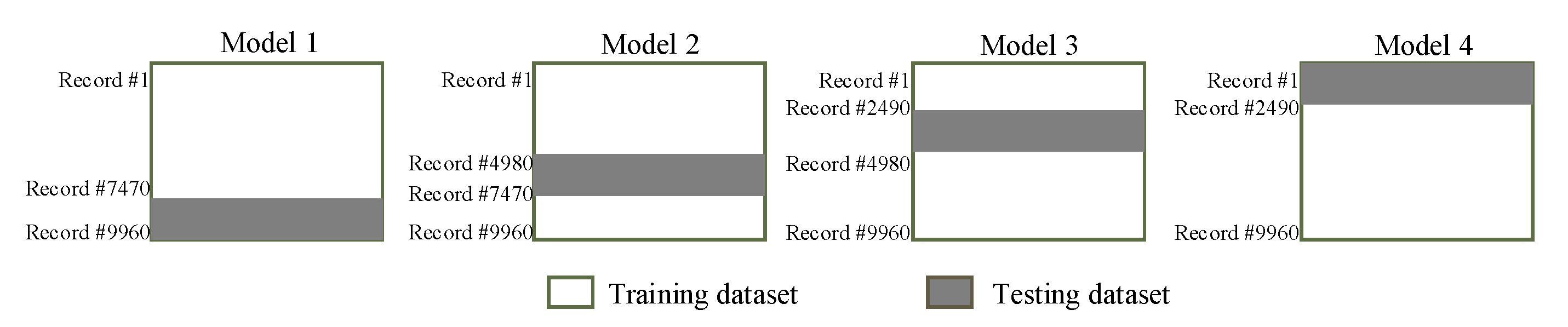
| Experiment ID | Position Error with Prediction Model (mm) | Position Error with Learning to Prediction Model (mm) |
|---|---|---|
| 1 | 0.132 | 0.105 |
| 2 | 0.115 | 0.099 |
© 2020 by the authors. Licensee MDPI, Basel, Switzerland. This article is an open access article distributed under the terms and conditions of the Creative Commons Attribution (CC BY) license (http://creativecommons.org/licenses/by/4.0/).
Share and Cite
Jamil, F.; Iqbal, N.; Ahmad, S.; Kim, D.-H. Toward Accurate Position Estimation Using Learning to Prediction Algorithm in Indoor Navigation. Sensors 2020, 20, 4410. https://doi.org/10.3390/s20164410
Jamil F, Iqbal N, Ahmad S, Kim D-H. Toward Accurate Position Estimation Using Learning to Prediction Algorithm in Indoor Navigation. Sensors. 2020; 20(16):4410. https://doi.org/10.3390/s20164410
Chicago/Turabian StyleJamil, Faisal, Naeem Iqbal, Shabir Ahmad, and Do-Hyeun Kim. 2020. "Toward Accurate Position Estimation Using Learning to Prediction Algorithm in Indoor Navigation" Sensors 20, no. 16: 4410. https://doi.org/10.3390/s20164410
APA StyleJamil, F., Iqbal, N., Ahmad, S., & Kim, D.-H. (2020). Toward Accurate Position Estimation Using Learning to Prediction Algorithm in Indoor Navigation. Sensors, 20(16), 4410. https://doi.org/10.3390/s20164410