Wireless Power Transfer Techniques for Implantable Medical Devices: A Review


Abstract
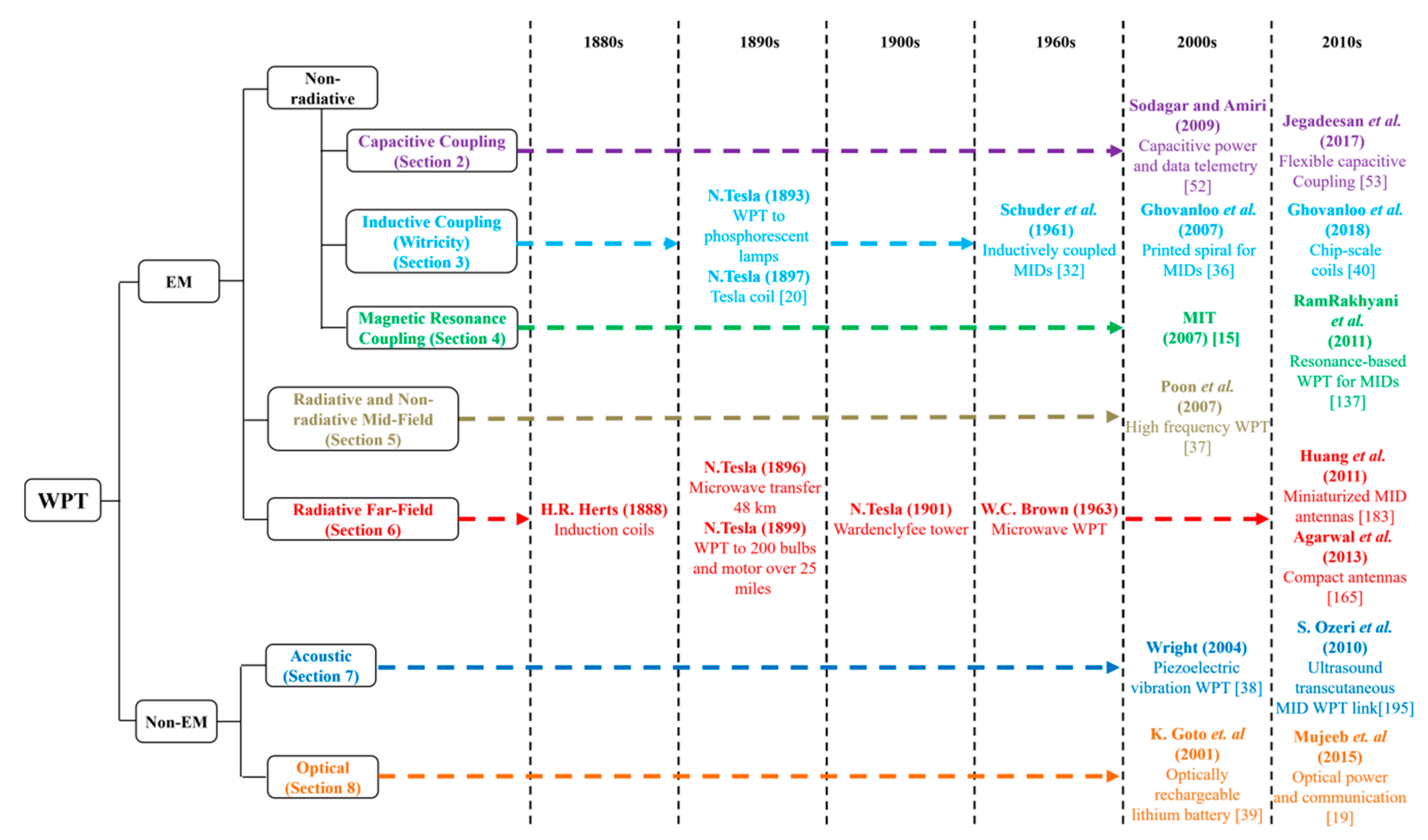
1. Introduction
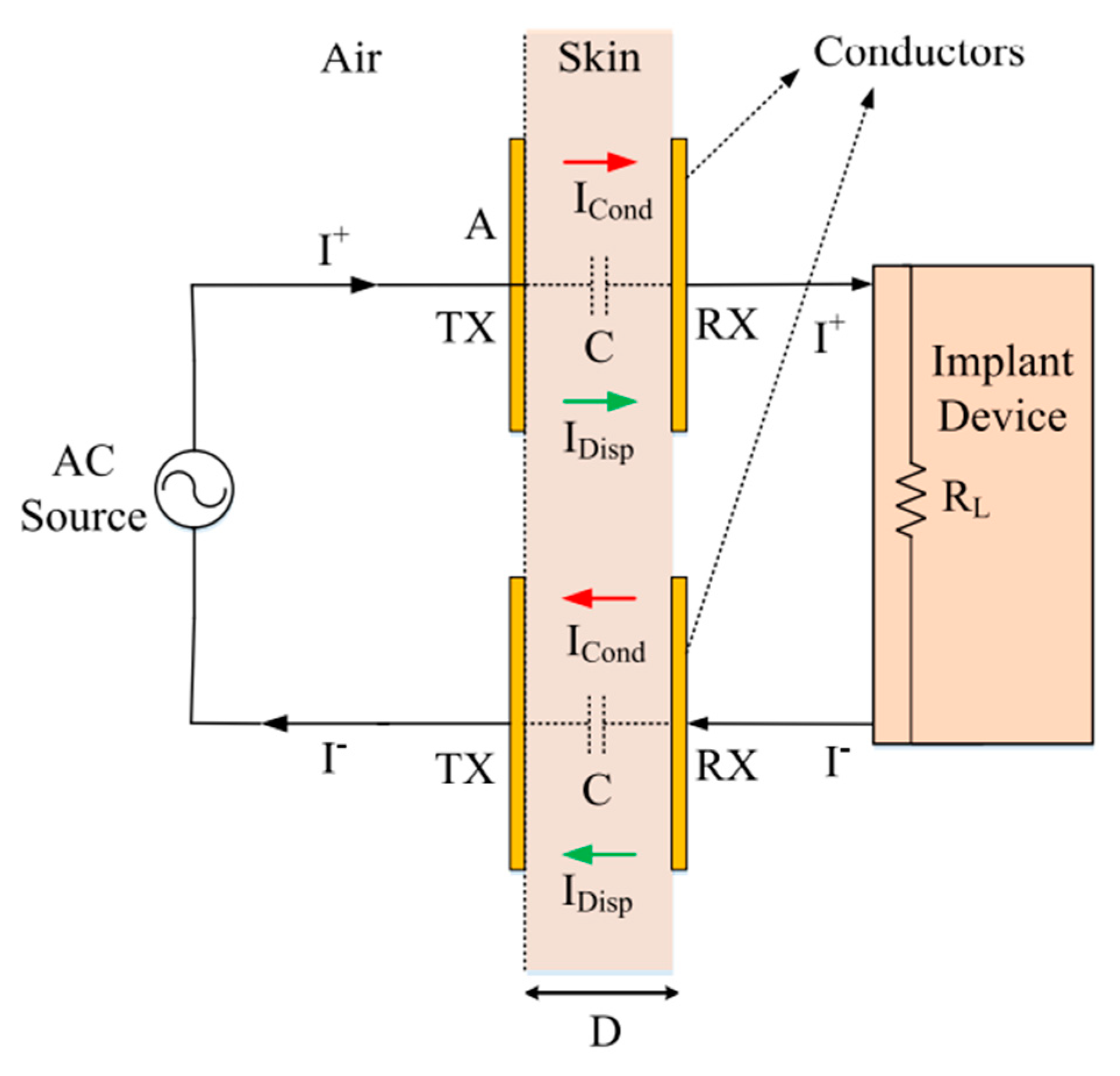
2. Non-Radiative Capacitor Coupling
2.1. Link Design
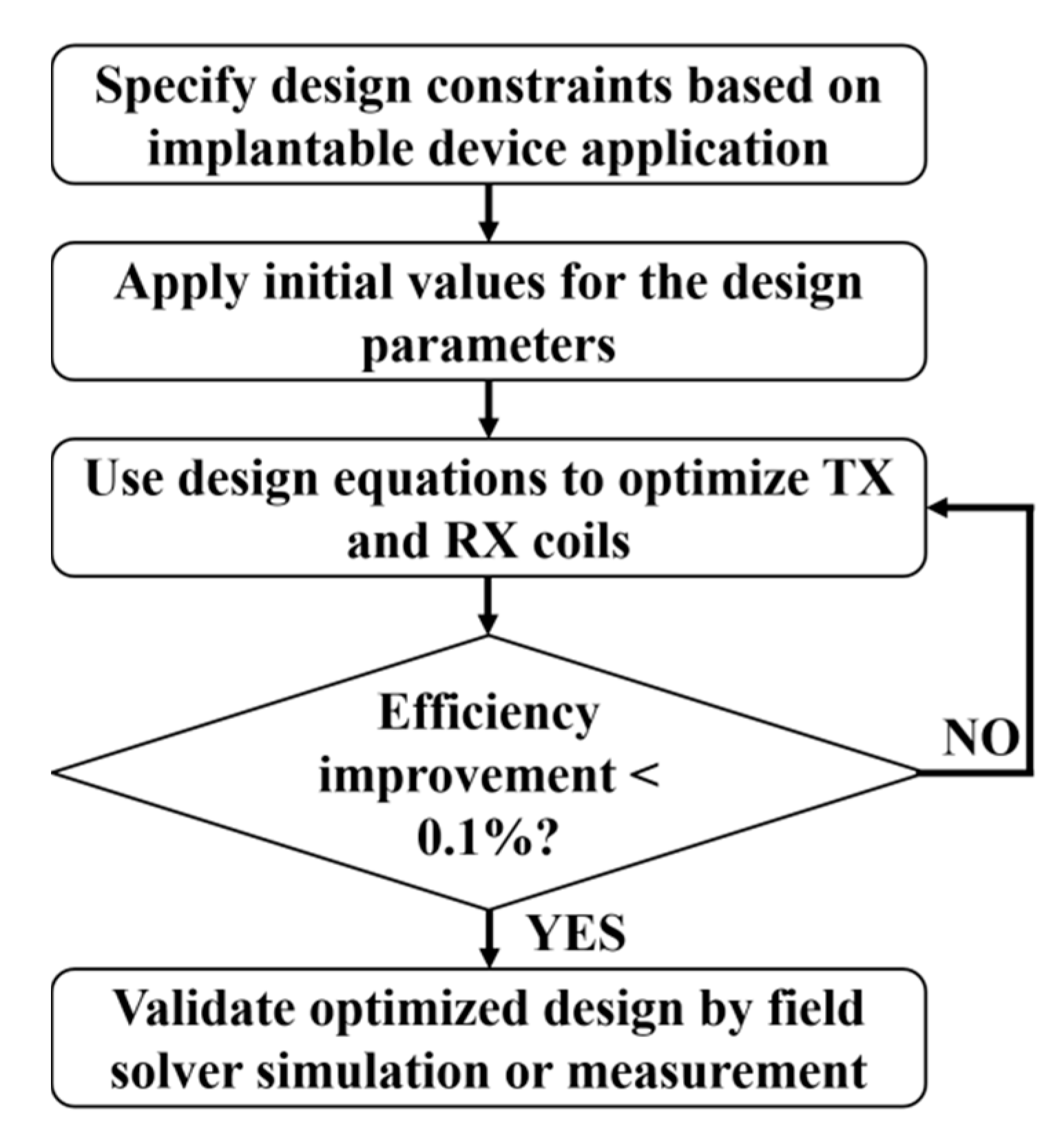
2.2. Optimization
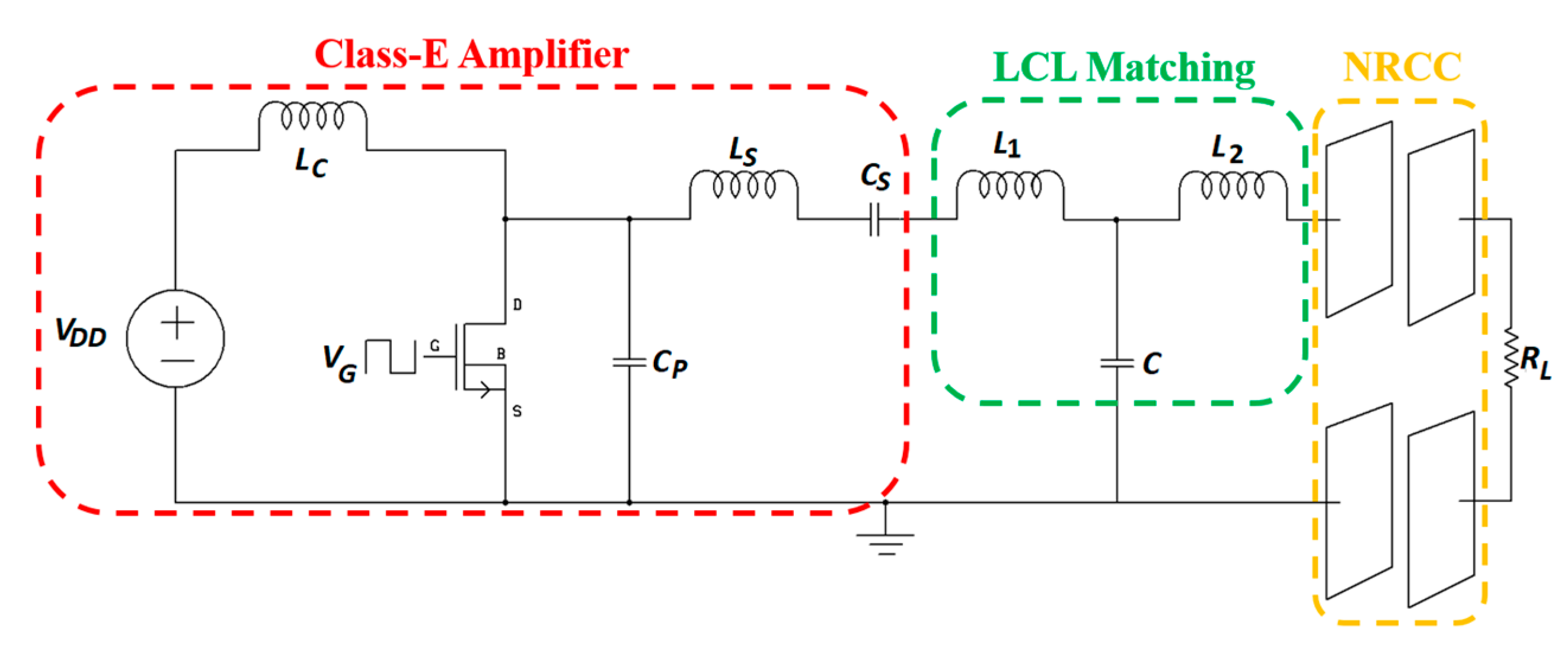
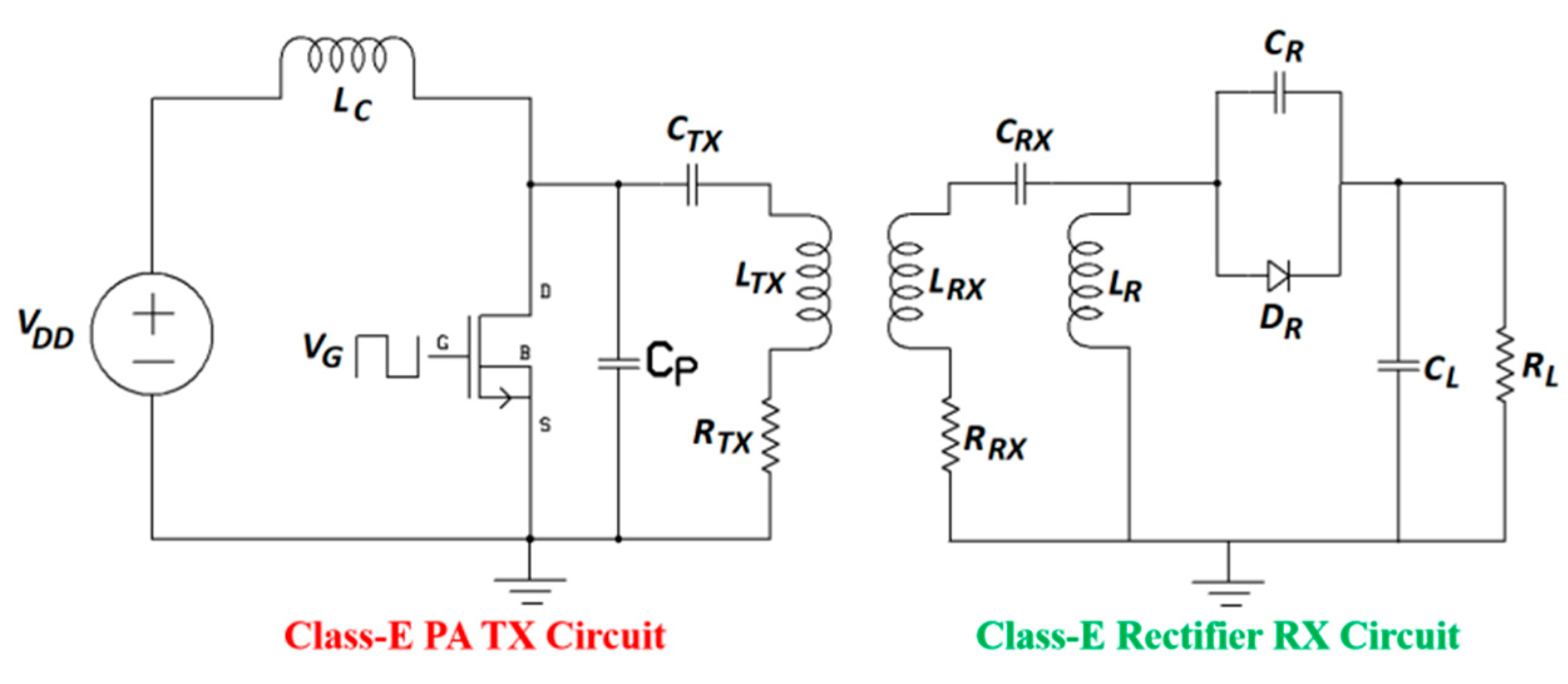
2.3. System Design
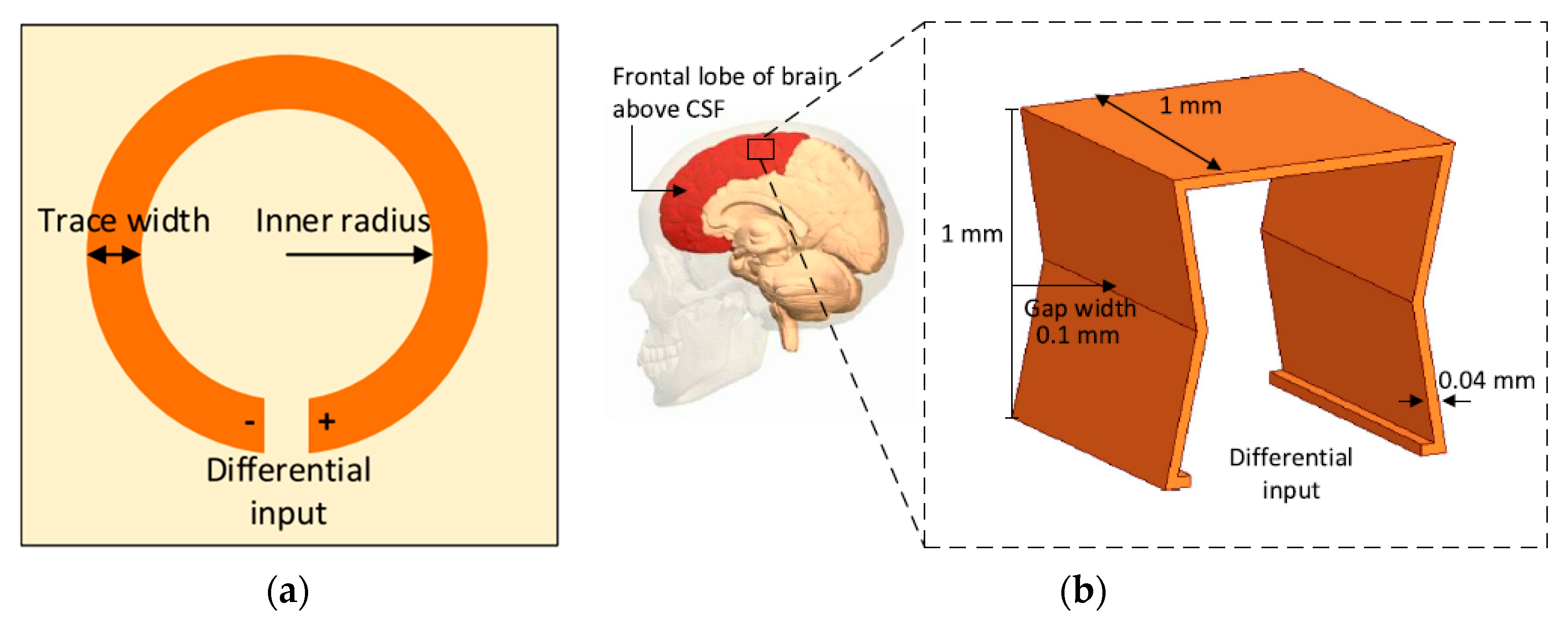
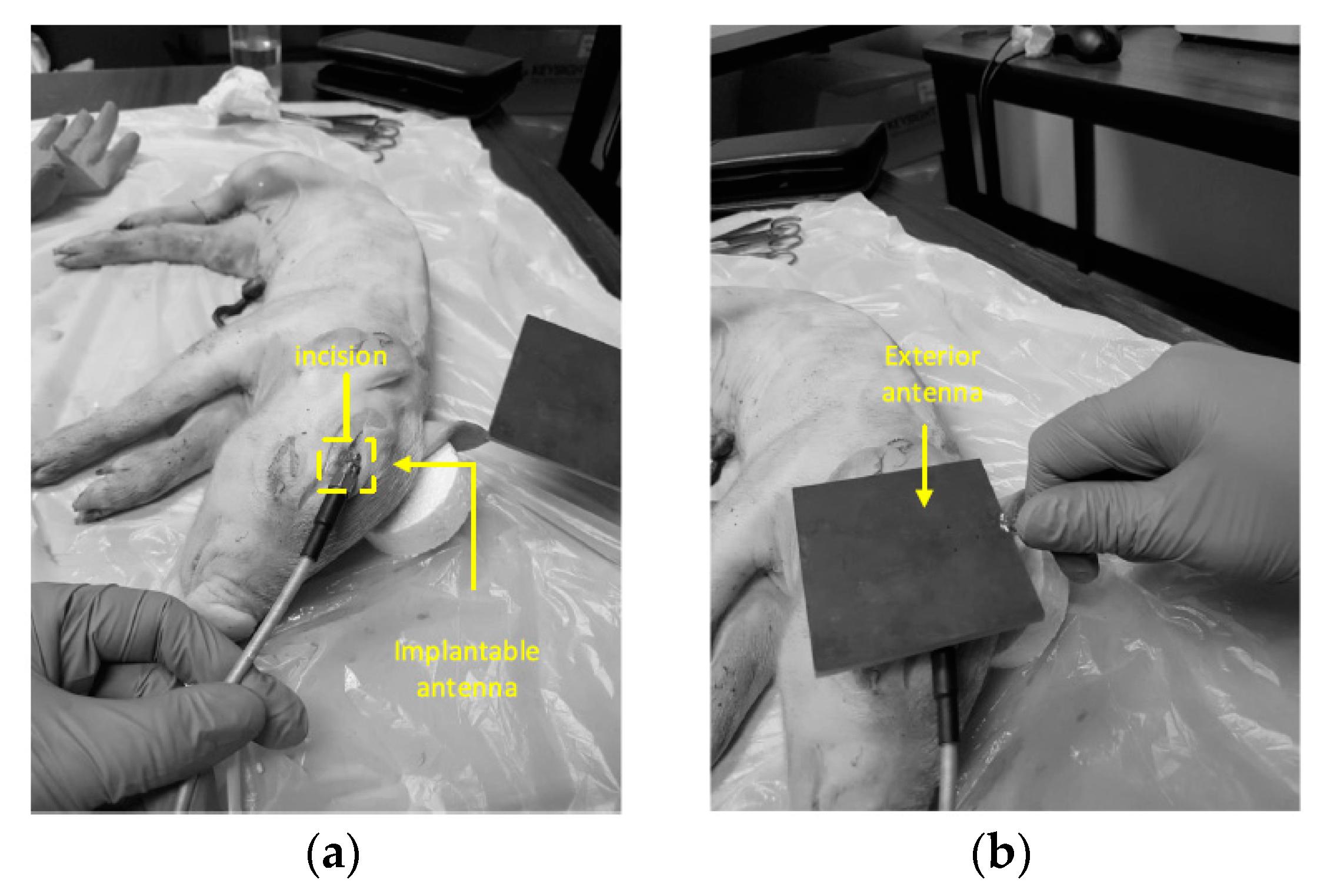
2.4. Applications
2.5. Design Challenges and Future Trends
- (1)
- The limited amount of power delivered by NRCC is an issue due to the low PTE. To improve the PTE, the capacitance must increase, requiring that the separation distance is very small, of the order of millimeters or below.
- (2)
- NRCC is sensitive to misalignment. Any misalignment reduces the capacitance coupling and leads to a substantial decrease in the PTE.
- (3)
- Efficient power processing (rectification) is difficult for a high operation frequency due to the difficulty in designing and implementing a high-efficiency rectifier for NRCC.
- (4)
- Extensive tissue safety analysis should be demonstrated before considering this method for in vivo applications, as no report is yet available regarding tissue safety.
2.6. Verdict
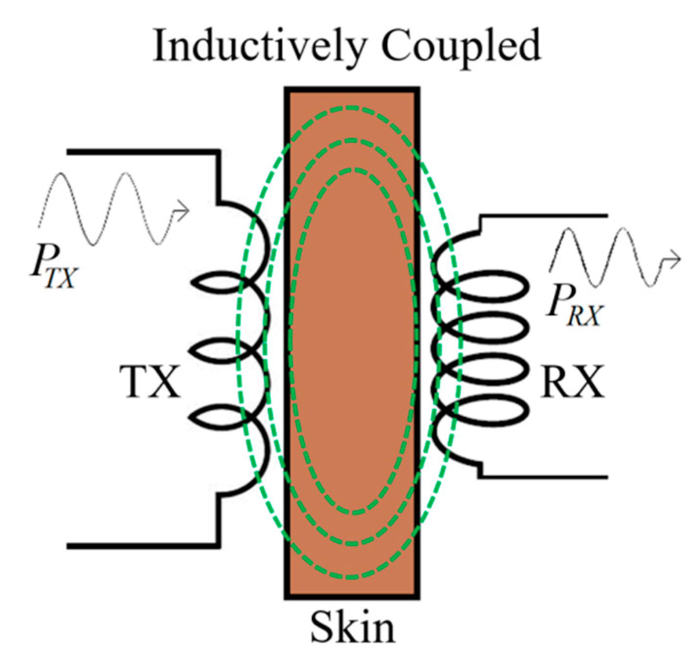
3. Non-Radiative Inductive Coupling
3.1. Link Design
3.2. Optimization
3.2.1. Self-Inductance
3.2.2. Mutual Inductance
3.2.3. AC Resistance
3.2.4. Parasitic Capacitance
3.2.5. PTE
3.2.6. Optimization Flow
3.3. System Design
3.4. Applications
3.4.1. Brain Implant
3.4.2. Neurostimulator Implants
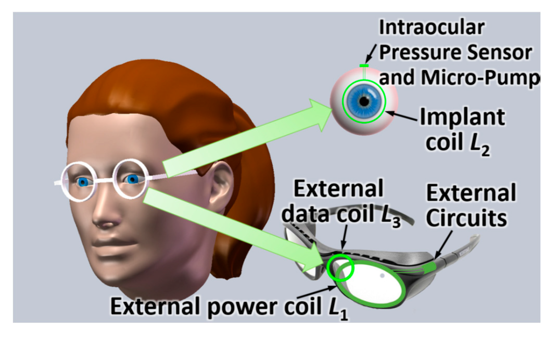
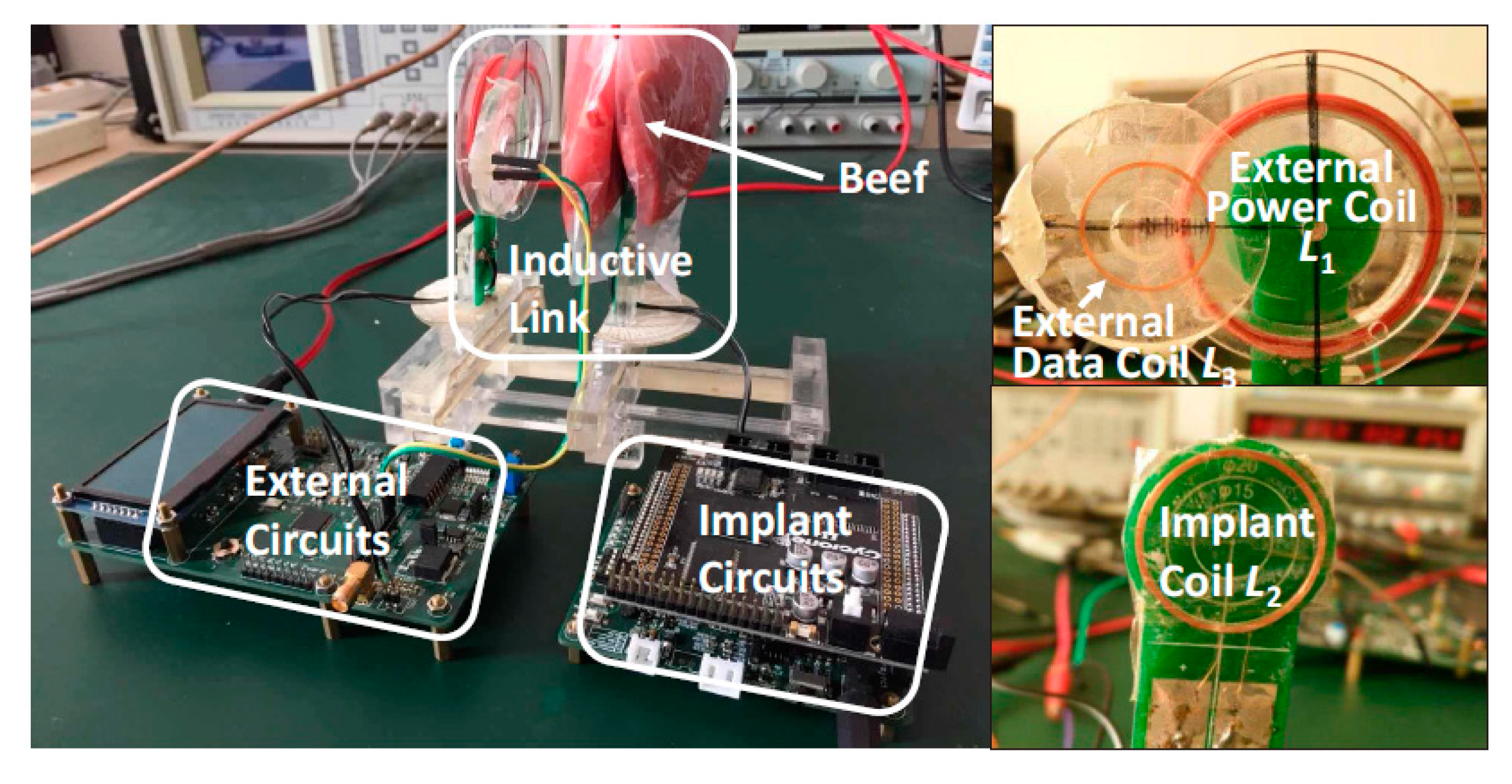
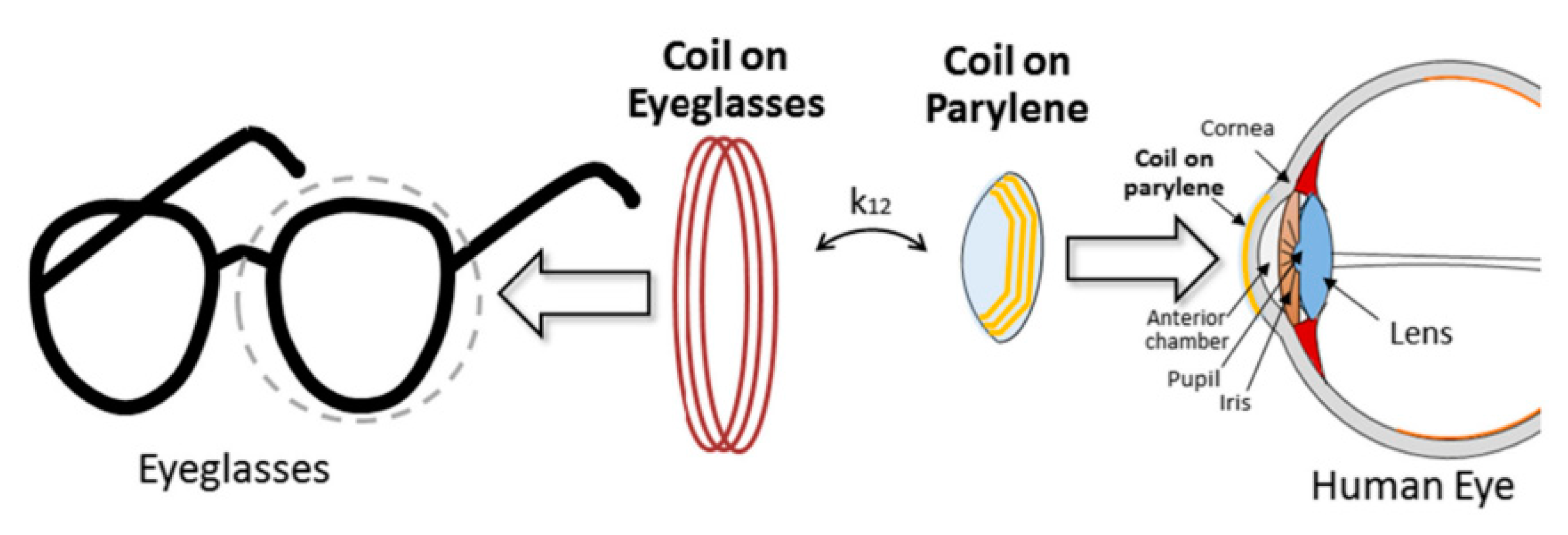
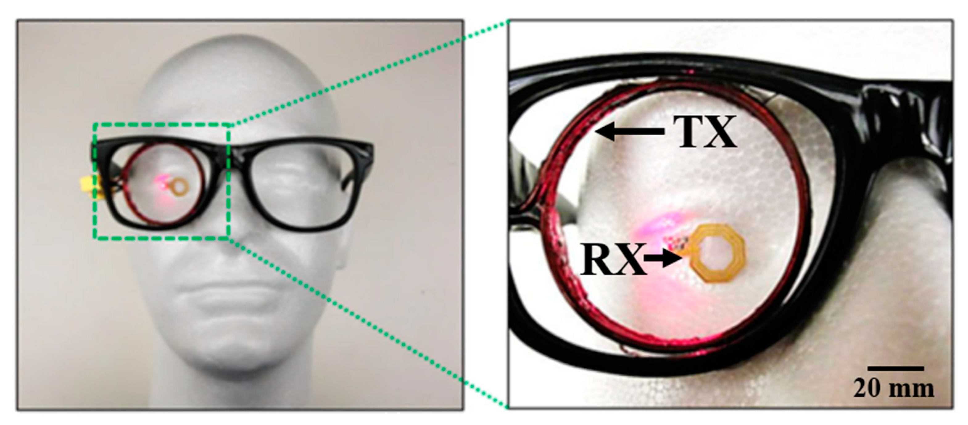
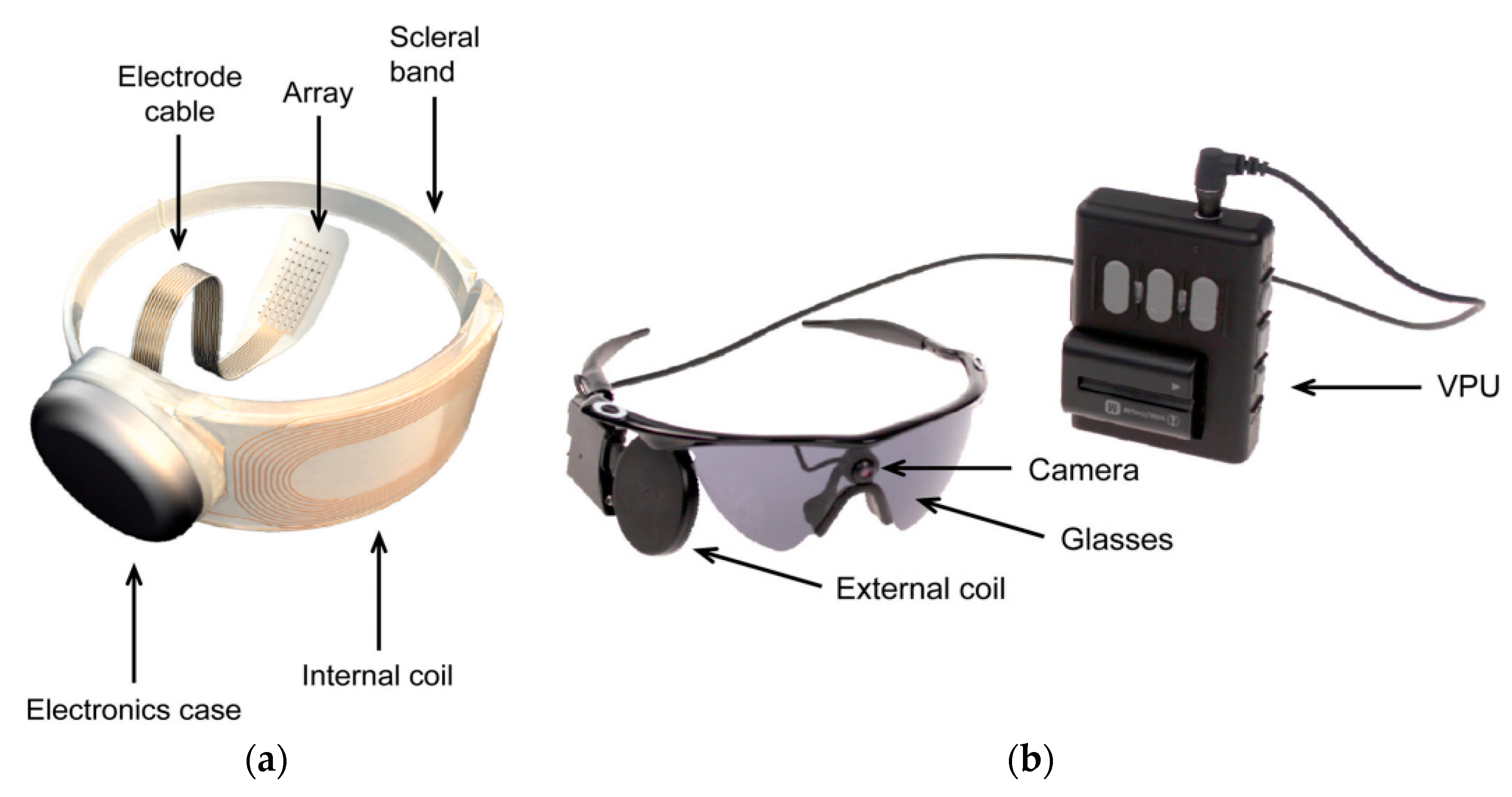
3.4.3. OcularImplant
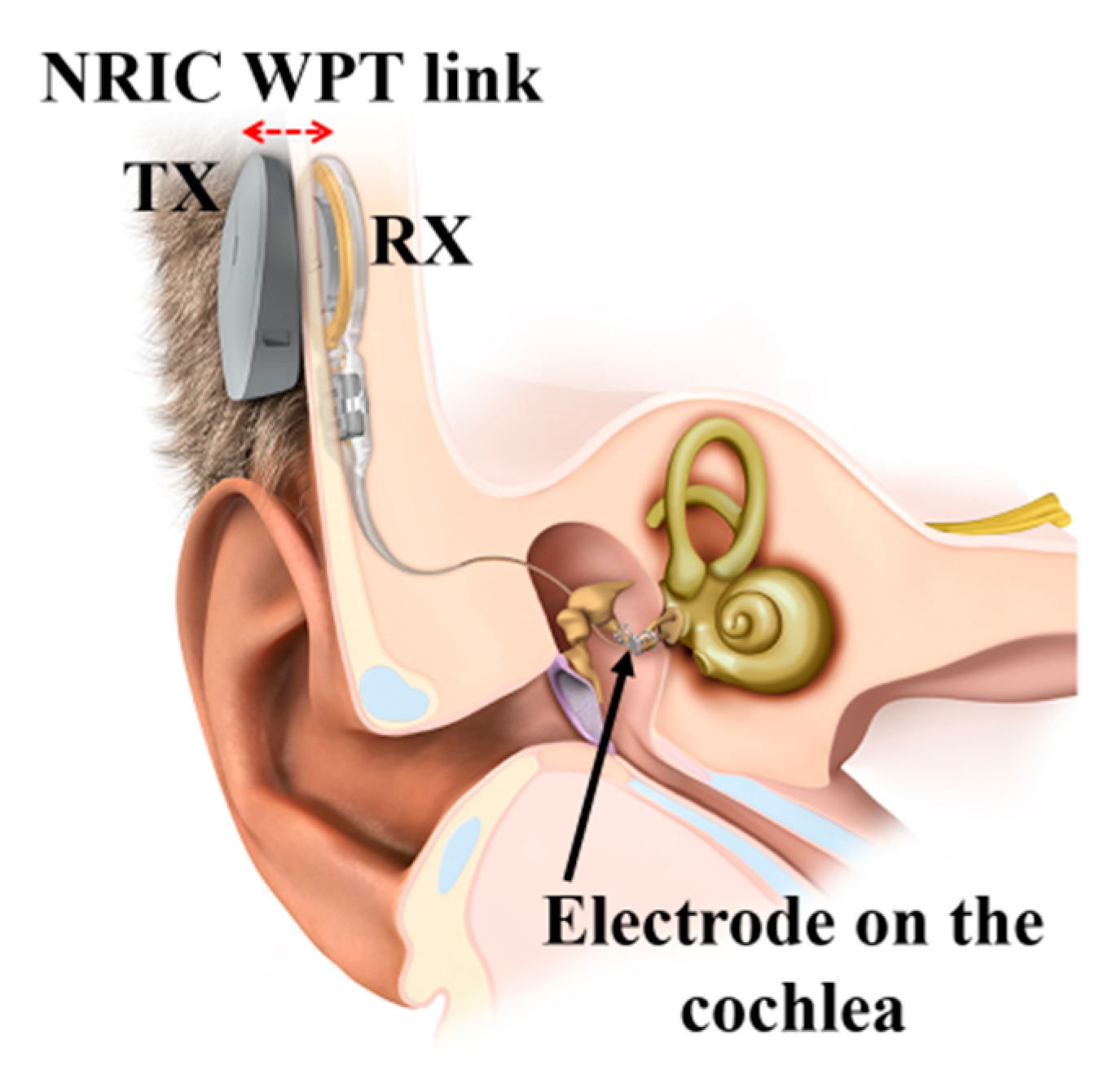
3.4.4. Cochlear Implant
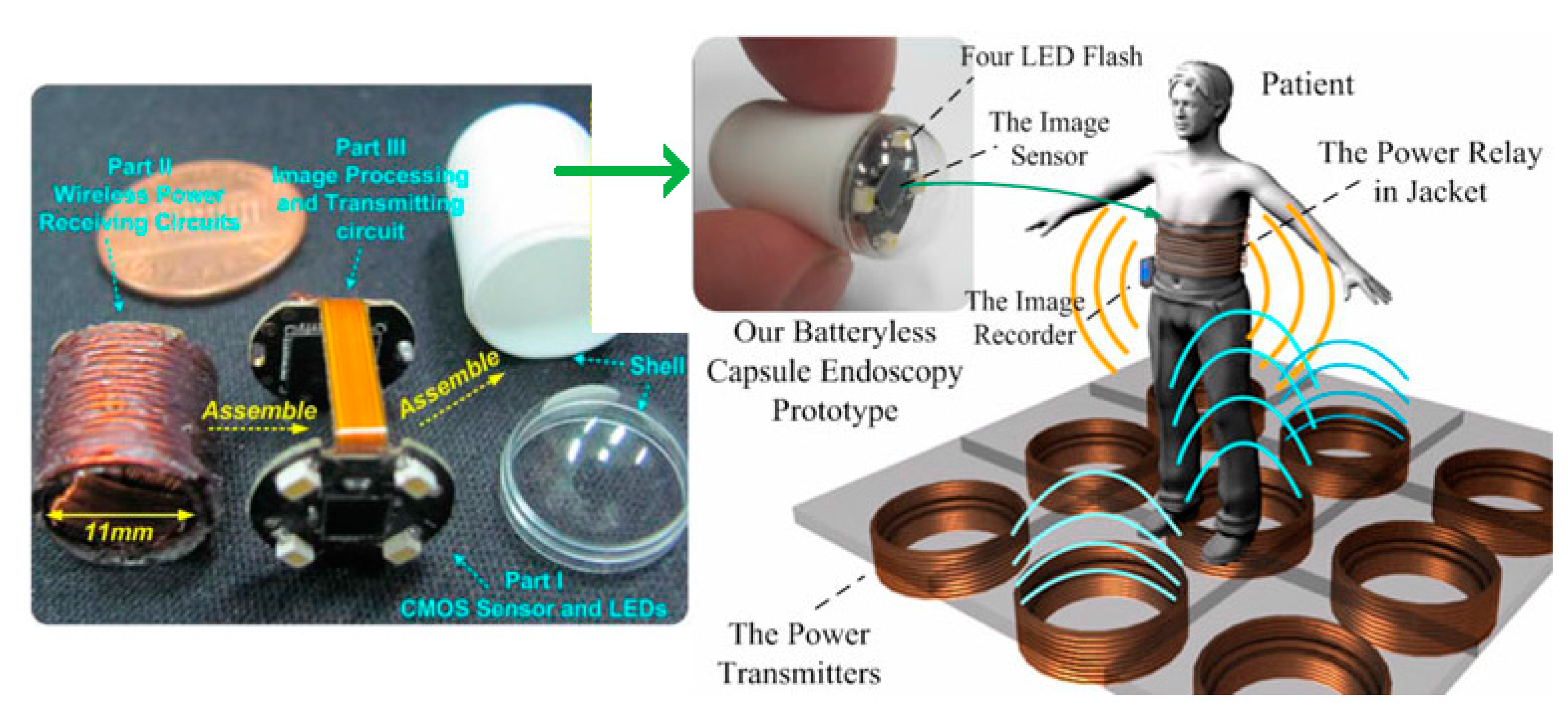
3.4.5. Capsule Endoscopy
3.5. Design Challenges and Future Trends
- (1)
- Optimization only for a particular load to achieve maximum power. Hence, the operation of such a link to extract efficient power in variable load conditions still remains to be resolved.
- (2)
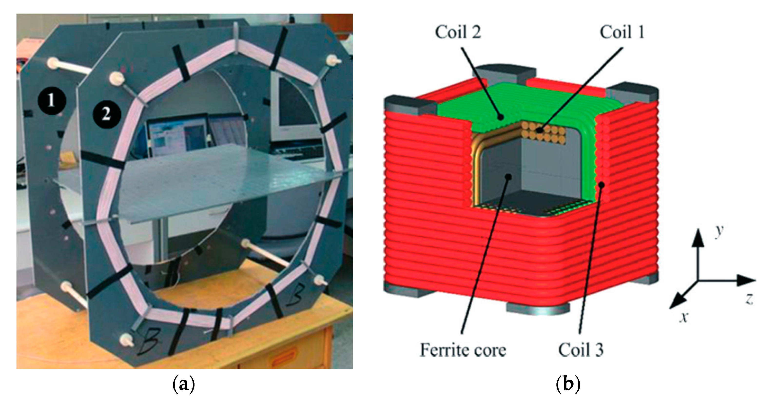
- Motion of MIDs can cause misalignment in the RX coil and reduce the efficiency of the WPT link. Therefore, recent research has focused on the 3D orthogonal WPT receiver architecture to mitigate the misalignment effect [123].
- (3)
- Robustness of performance of flexible implantable NRIC coils is another important design challenge. Severe mismatch of the resonance capacitance can occur due to the flexion characteristics of the implant coils [124]. Therefore, self-tuning circuitry is required to keep the transfer efficiency stable. Some attempts have been reported to address the self-tuning of the NRIC WPT resonators [125,126].
- (4)
- The large power requirement of some multi-functional implantable devices might prohibit the use of a WPT system that could generate an SAR above 2 W/kg, the recommended limit regarding safety of human tissues [117,127]. It is unfortunate that most researchers fail to measure the SAR of their designed coils.
- (5)
- Biocompatibility of the material used for the implanted coil is not published widely in the literature. This information is of critical importance to facilitate medical acceptability of the implant.
3.6. Verdict
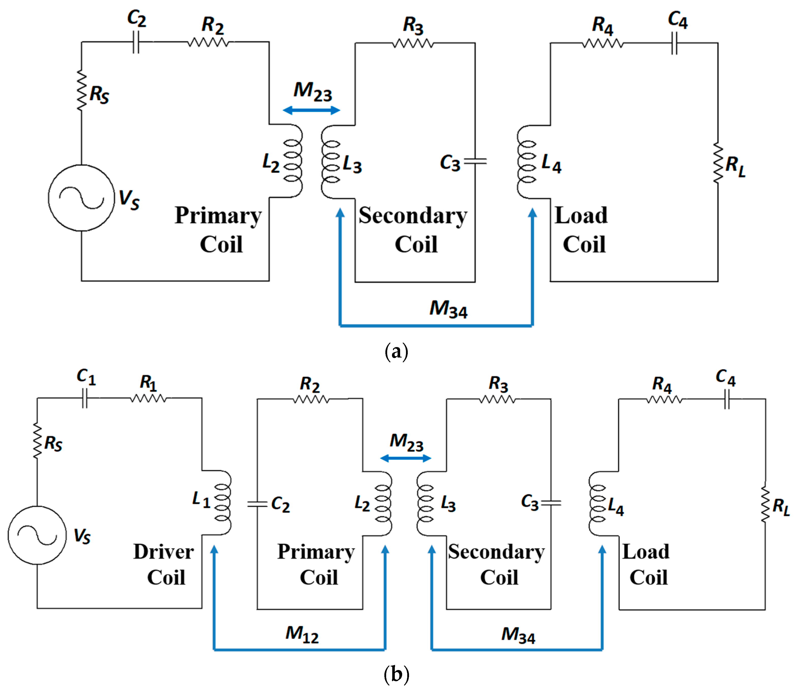
4. Non-Radiative Magnetic Resonance Coupling
4.1. Link Design
4.2. Optimization
4.3. System Design
4.4. Applications
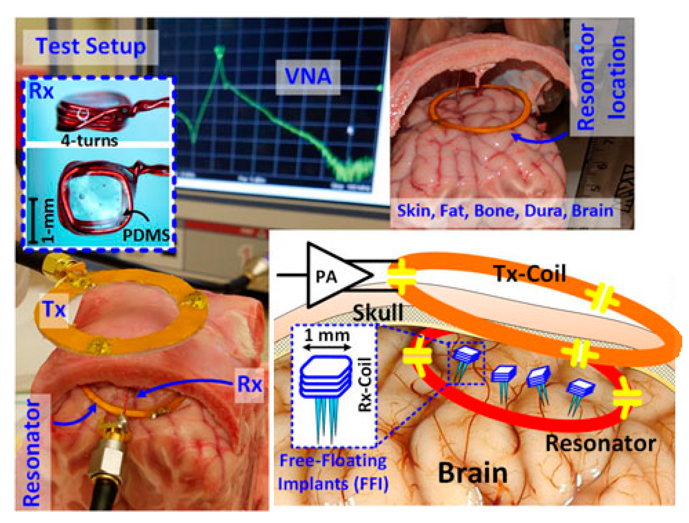
4.4.1. Brain Implant
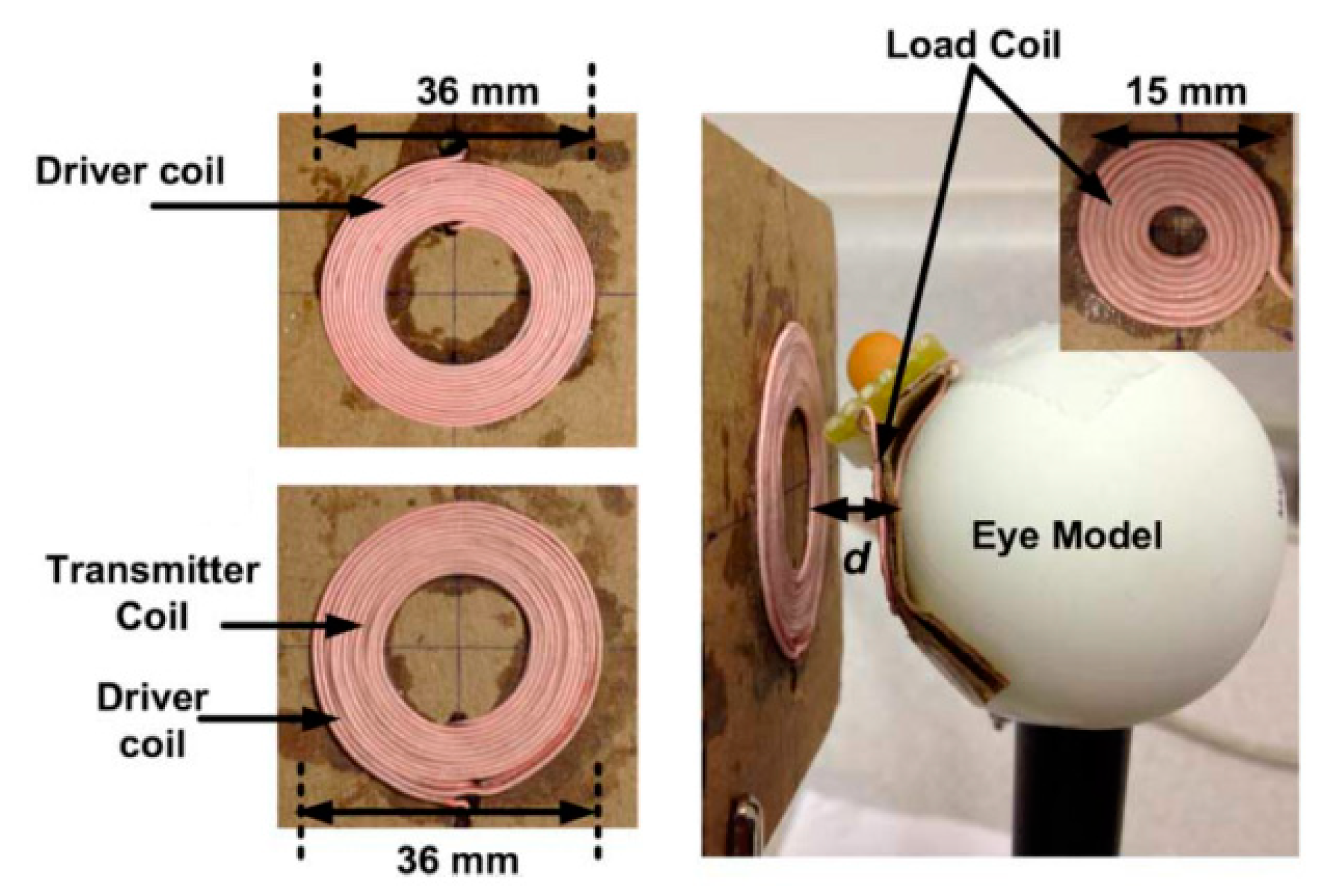
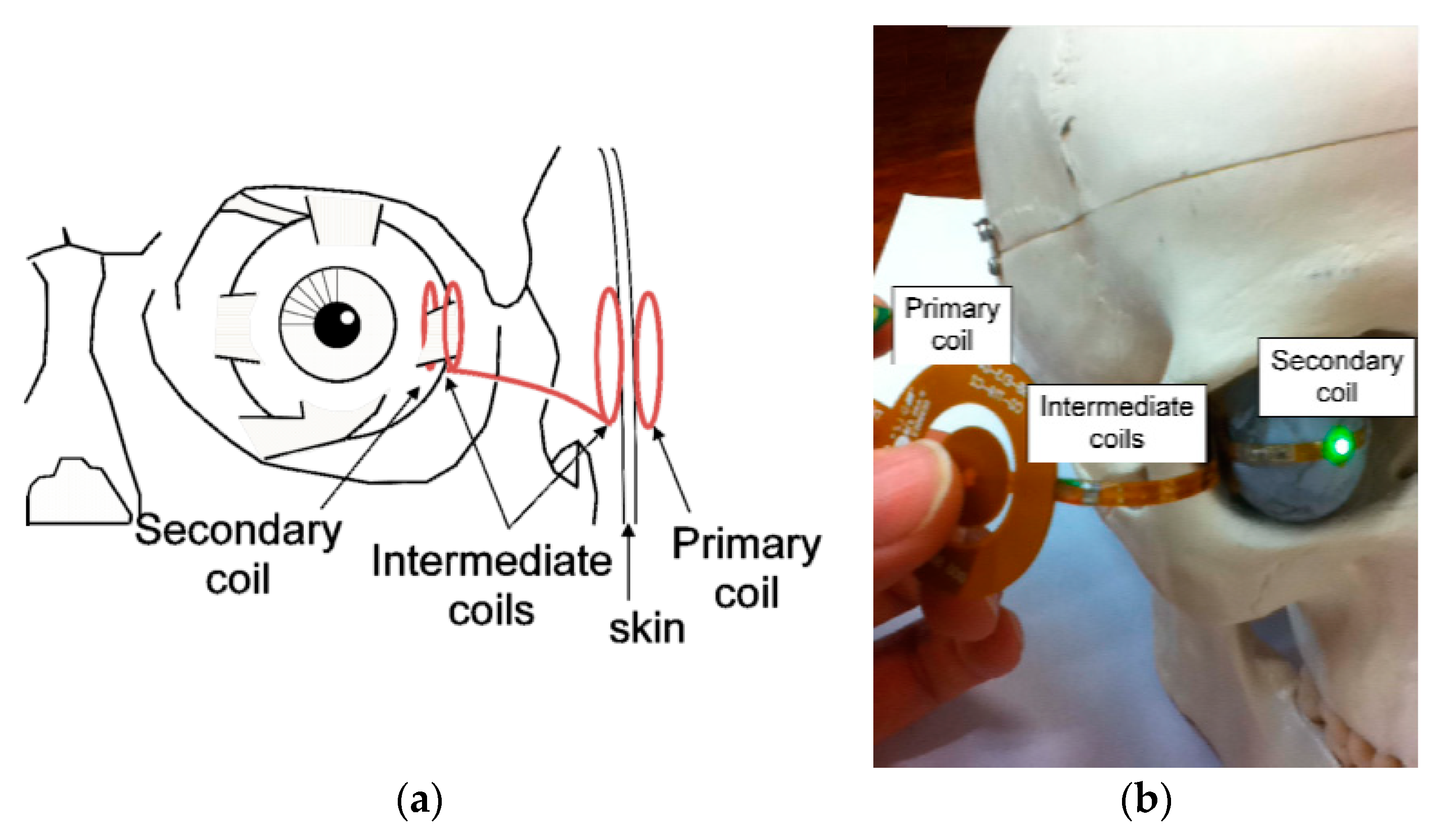
4.4.2. Ocular Implant
4.4.3. Capsule Endoscopy
4.5. Design Challenges and Future Trends
- (1)
- The design and optimization complexity is higher than the NRIC due to the multi-coil-based architecture.
- (2)
- The size of the implanted coil is problematic for biomedical applications. Using multiple RX coils (secondary and load coils) increases the real-estate required.
- (3)
- It is challenging to align secondary and load coils inside the human body. This problem is compounded by the fact that the effects of misalignment on the PTE are worse for NRMRC compared to NRIC due to the multi-coil-based architecture.
- (4)
- The parasitic capacitance is usually used to tune the TX and RX coils to their resonating frequency [63]. Additionally, the biological tissue has a higher dielectric constant than the free space [69], which can increase the parasitic capacitance of the implanted coil [137]. Hence, the PTE can be affected by the parasitic capacitance inside the biological tissue.
- (5)
- NRMRC WPT systems have a higher operating frequency than their NRIC counterparts. Therefore, the SAR is prone to the safety limit and must be studied carefully.
4.6. Verdict
5. Mid-Field WPT
5.1. Link Design
5.2. Optimization
5.3. System Design
5.4. Applications
5.4.1. CardiacImplant
5.4.2. Neurostimulator Implant
5.4.3. Capsule Endoscopy
5.5. Design Challenges and Future Trends
- (1)
- The output power of NRRMF WPT systems is very low, which limits the range of applications for this method. The lower PTE limits the output power due to the higher separation distance in NRRMF. It is possible to increase the output power by improving the TX power within tissue safety guidelines.
- (2)
- The PTE in this technique is maximized by focusing the TX power towards the RX. Hence, the influence of misalignment on the PTE could be significant and needs to be studied carefully before considering this technology.
- (3)
- The design of high-efficiency amplifier and rectifier at sub-GHz and GHz frequency can be a challenging task.
- (4)
- Tissue safety is the major issue of concern due to the higher frequency region selected for this method.
5.6. Verdict
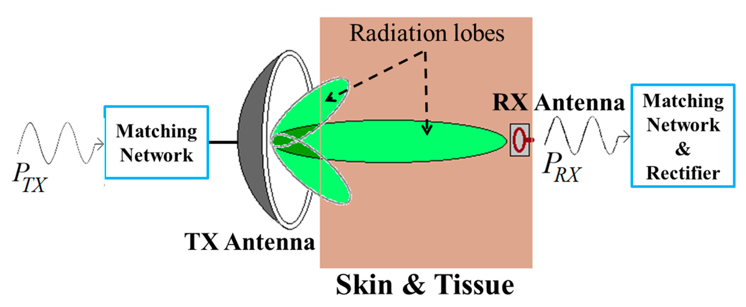
6. Radiative Far-Field
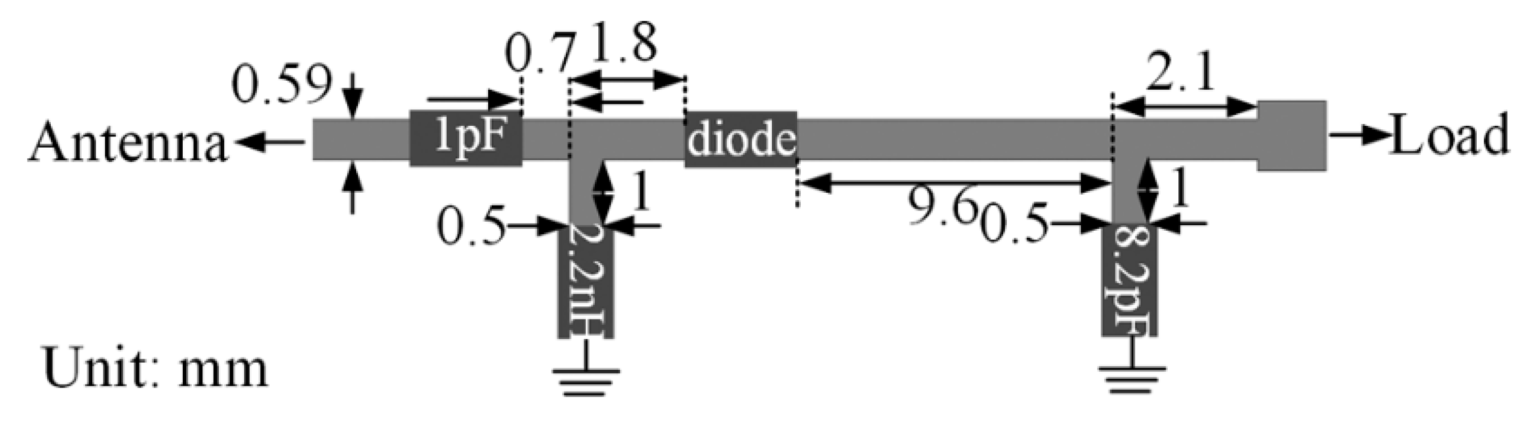
6.1. Link Design
6.2. Optimization
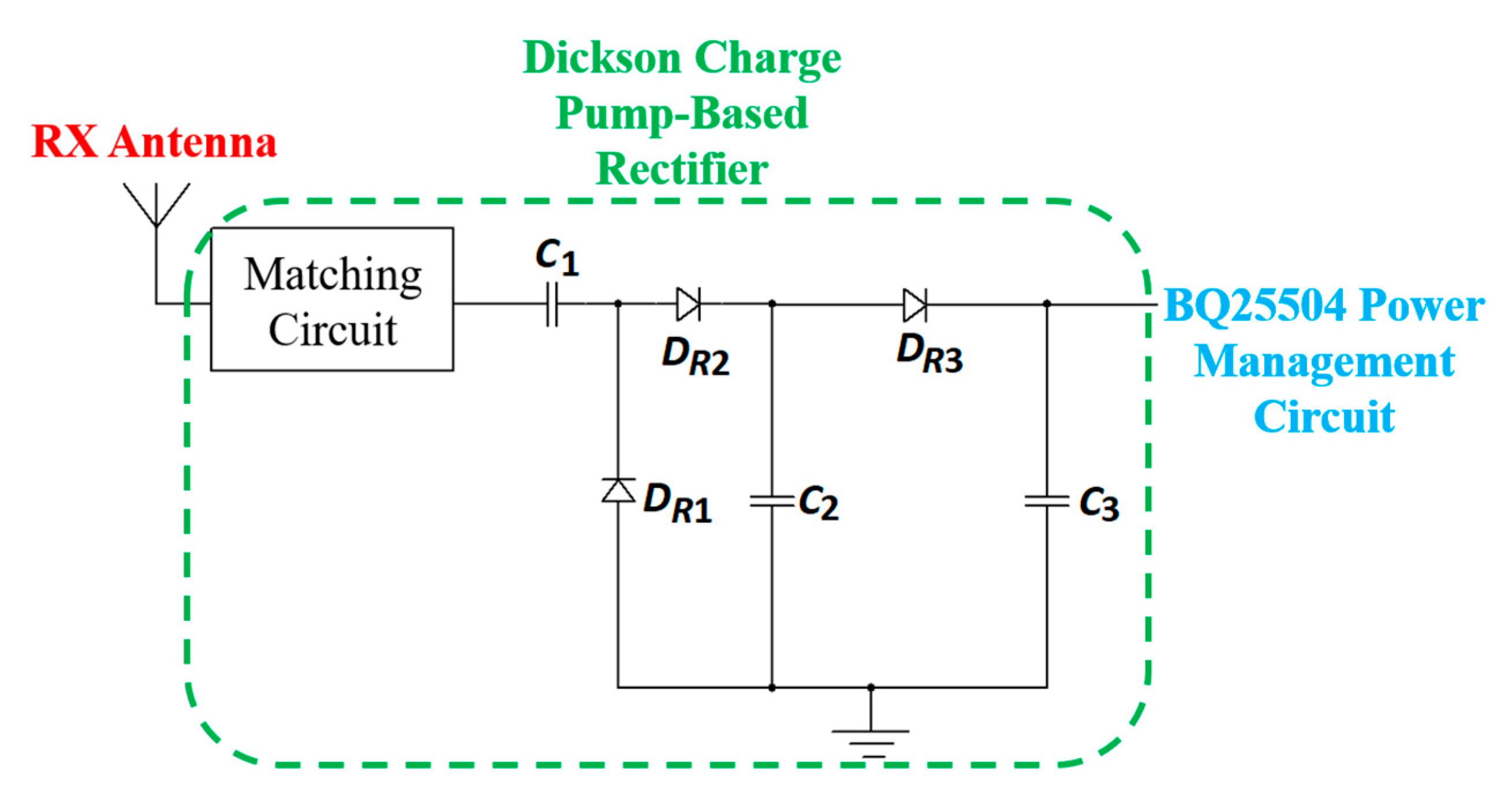
6.3. System Design
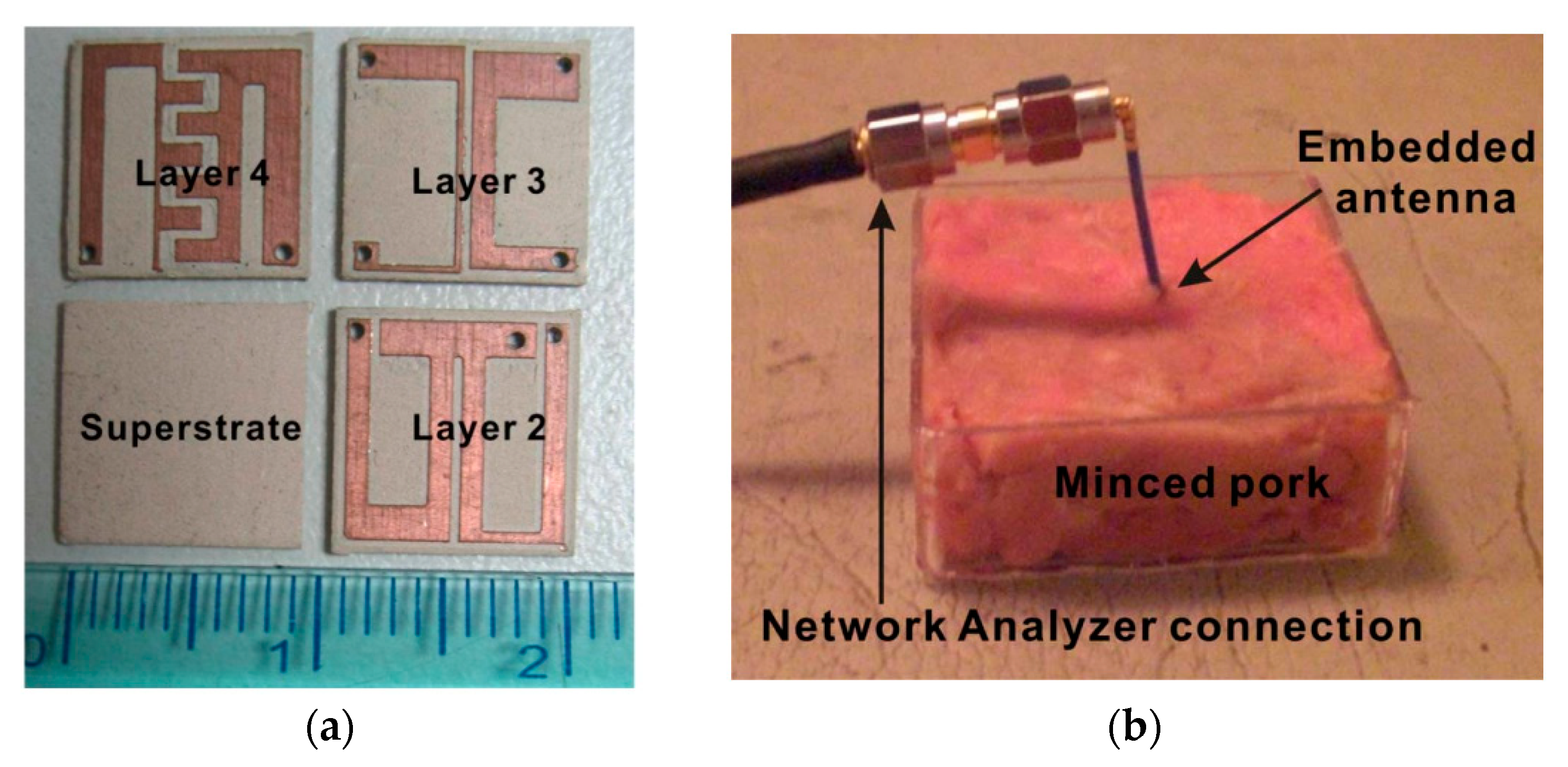
6.4. Applications
6.5. Design Challenges and Future Trends
- (1)
- One of the significant limitations of RFF powering in free space is the power density decrease as 1/d2 due to energy spreading [162]. In the case of implantable devices, the power density attenuation increases significantly as the EM waves pass through biological tissue.
- (2)
- To satisfy the safety regulations set by the FDA and FCC for far-field based WPT systems, the radiated TX power and received power at the implant side are small compared to the NRIC and NRMRC WPT systems.
- (3)
- The design complexity of the TX and RX circuits increases because of the higher operating frequency of the RFF WPT system.
6.6. Verdict
7. Acoustic Power Transfer
7.1. Link Design
7.2. Optimization
7.3. System Design
7.4. Applications
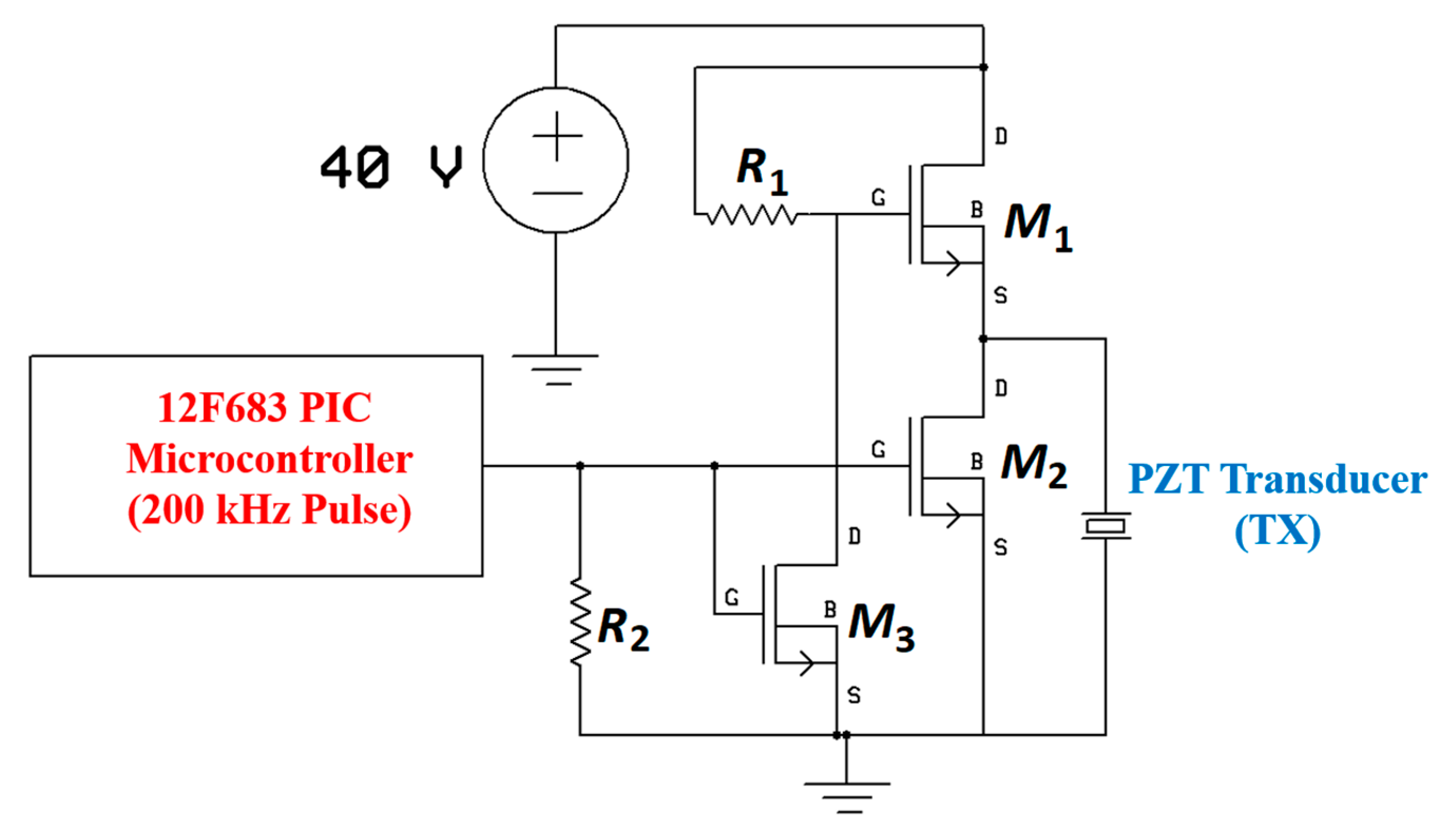
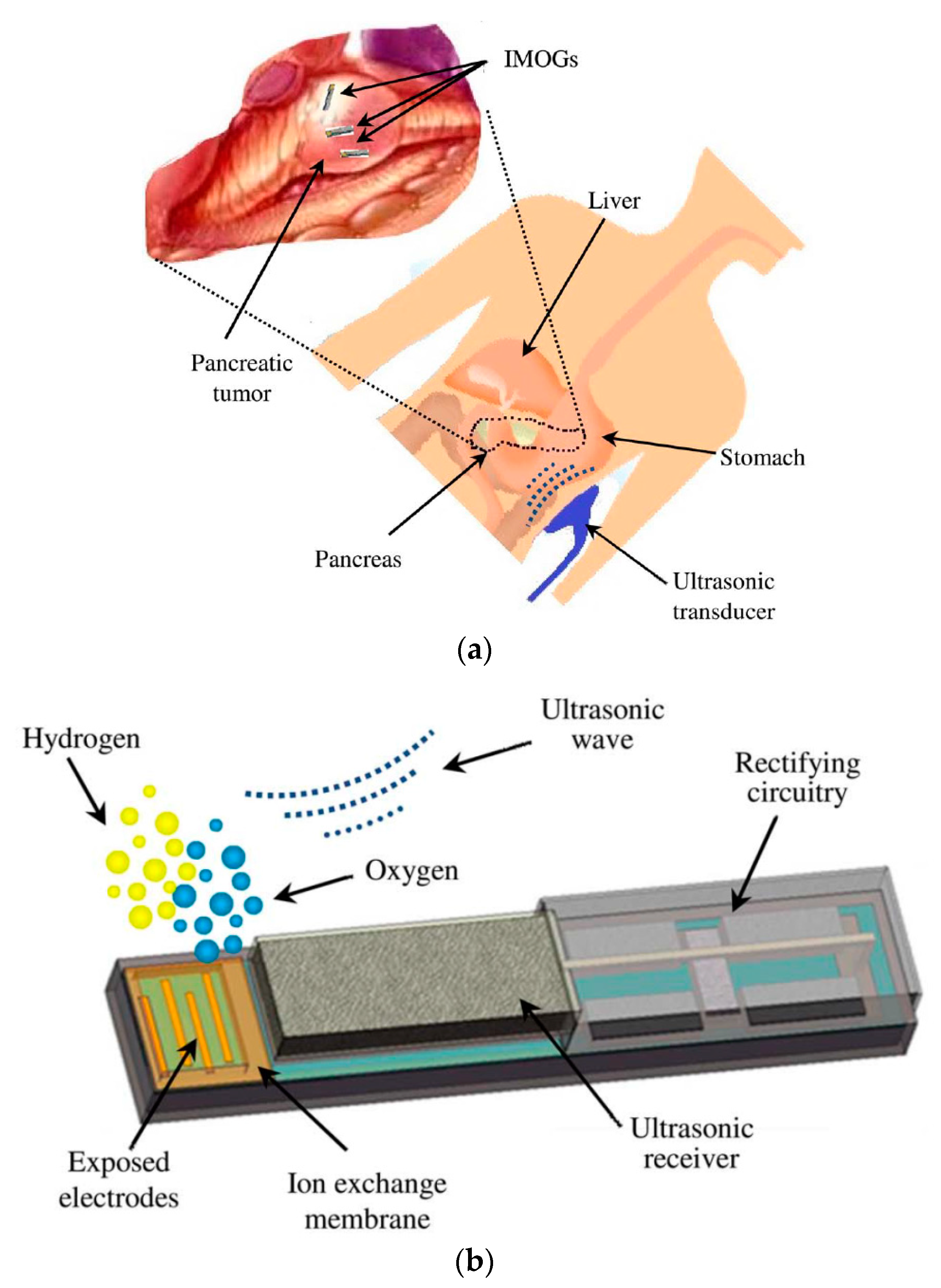
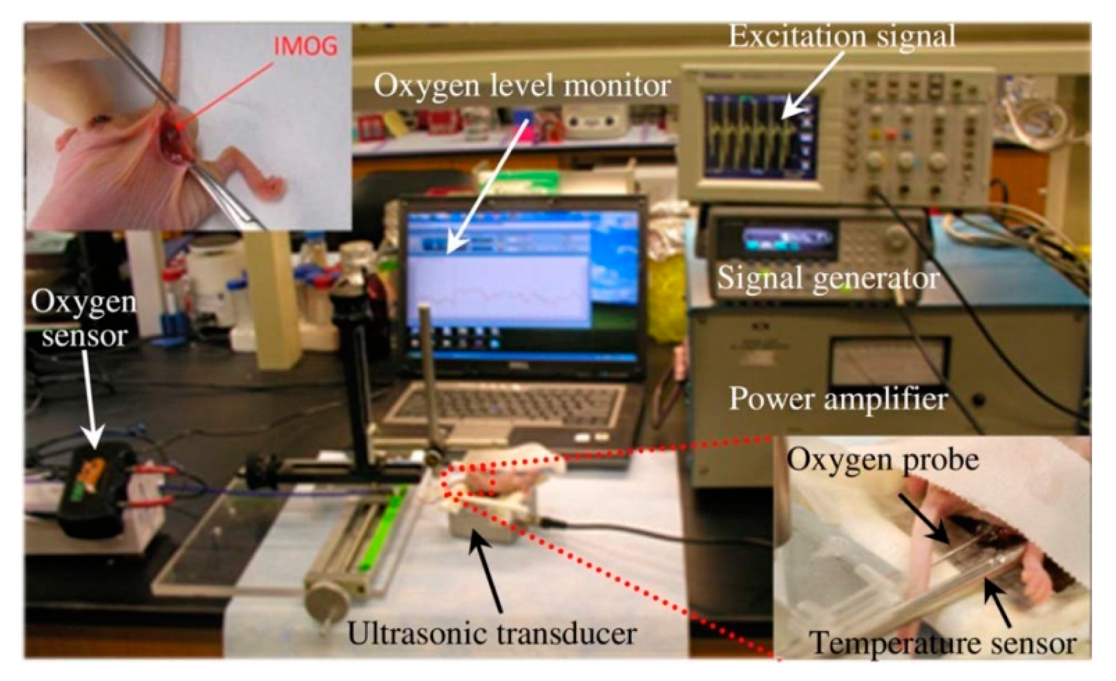
7.4.1. Micro-Oxygen Generator
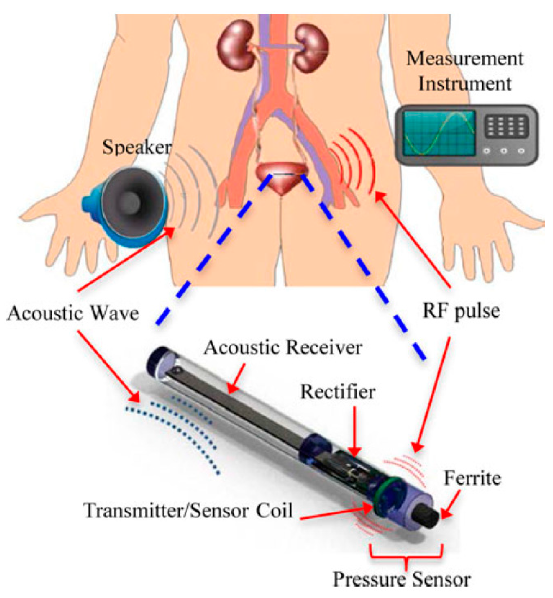
7.4.2. Bladder Pressure Sensing
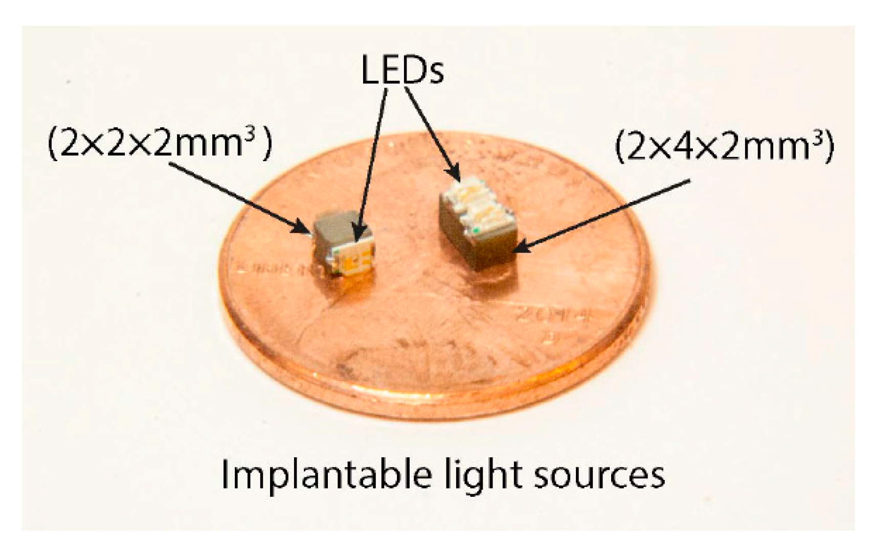
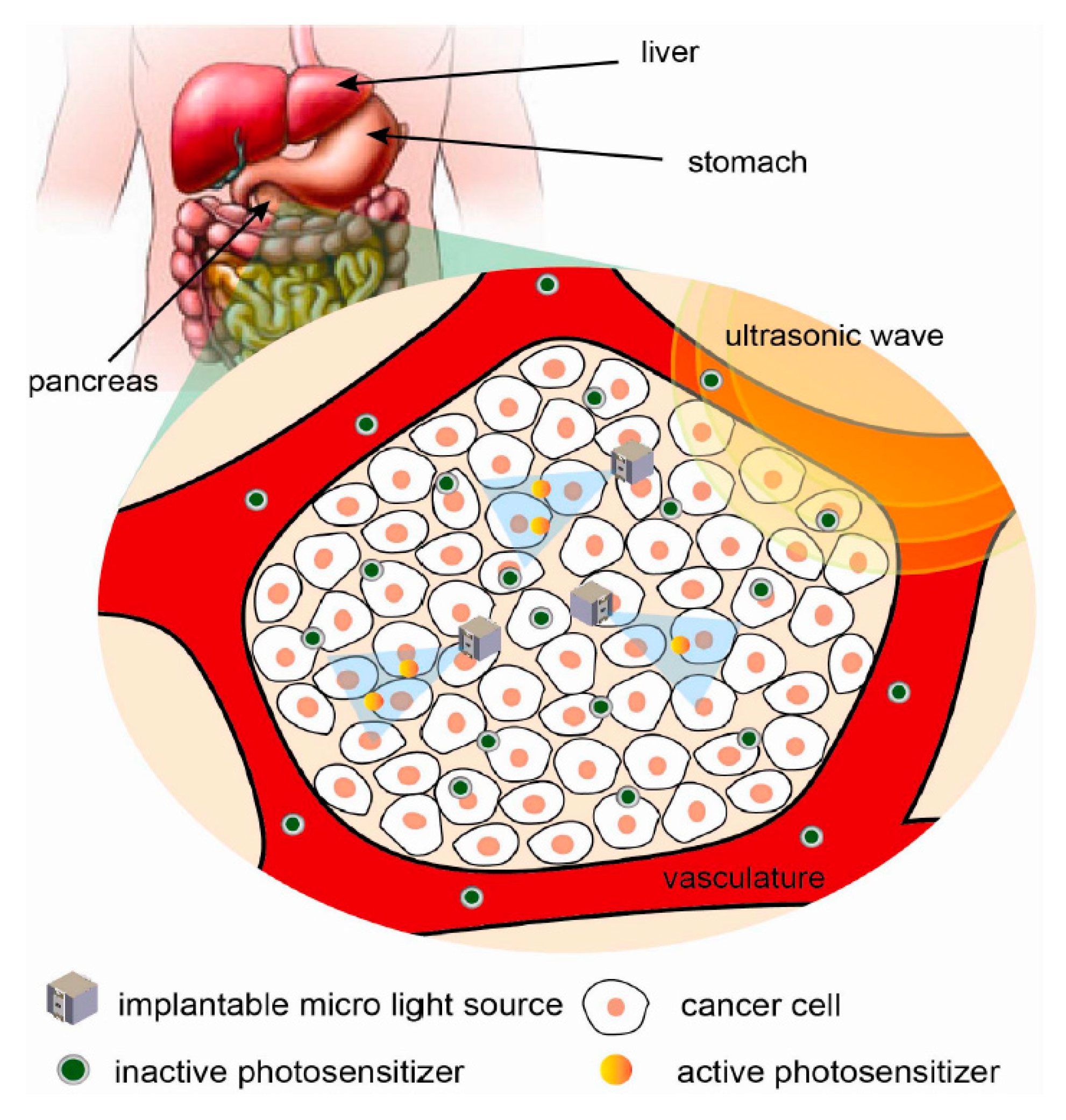
7.4.3. Localized Photodynamic Therapy
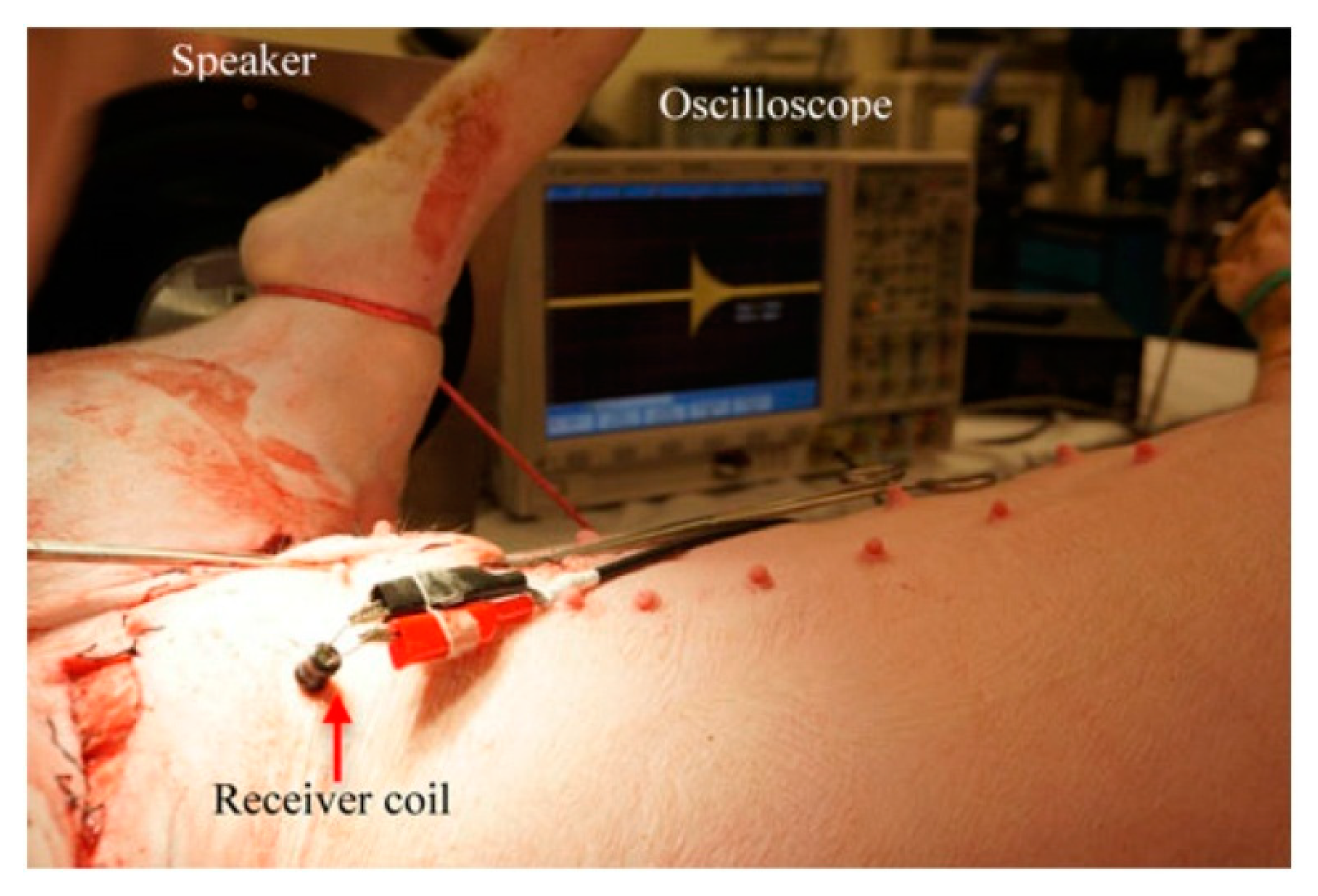
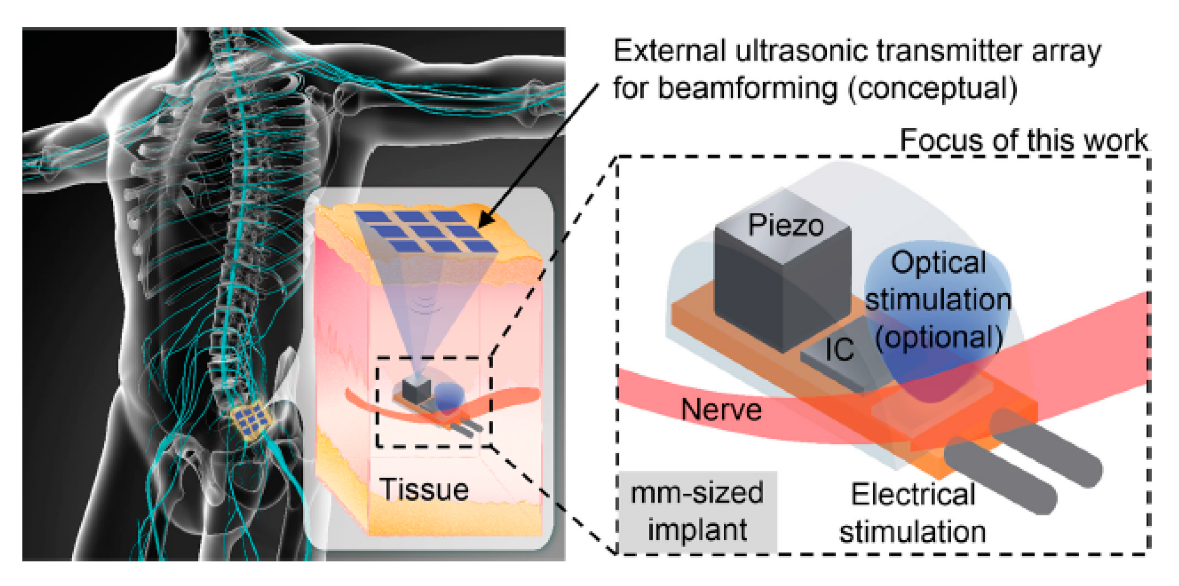
7.4.4. Electrical Stimulation of Peripheral Nerves
7.5. Design Challenges and Future Trends
- (1)
- One of the significant challenges associated with designing an APT system is the different density and acoustic impedance of different organs in the human body. The acoustic impedance of bones is high enough to reflect all ultrasound waves. Attenuation of sound by the soft tissue layers increases exponentially with increasing frequency and distance [209,210]. Therefore, APT is limited to specific body parts for powering implanted devices. Continuous tissue vibration is another health concern for APT systems [211].
- (2)
- For deep implants where the TX and RX separation is of the order of several acoustic wavelengths, the PTE is sensitive to a change of the distance between TX and RX as well as temperature-dependent tissue properties and tissue growth. The misalignment of TX and RX can affect the PTE of APT drastically compared to EM-based WPT systems.
- (3)
- The design of an APT transducer requires advanced design expertise than most of the EM-based WPT coils and antennas. Additionally, it is a costlier manufacturing process than EM WPT coils.
7.6. Verdict
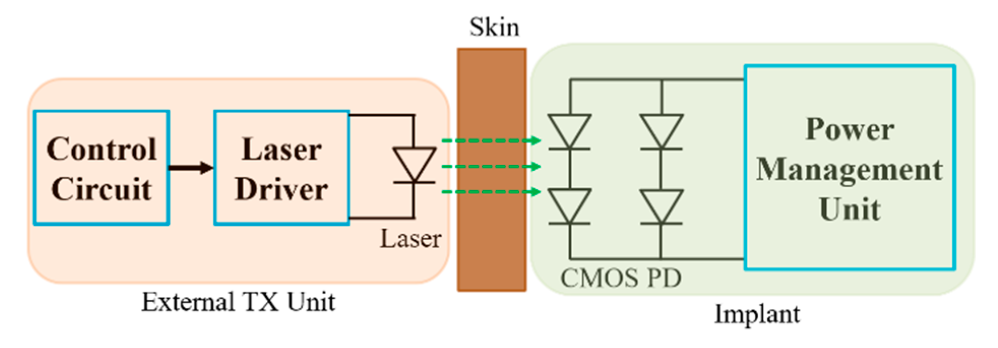
8. Optical Power Transfer
8.1. Link Design
8.2. Optimization
8.3. System Design
8.4. Applications
8.5. Verdict
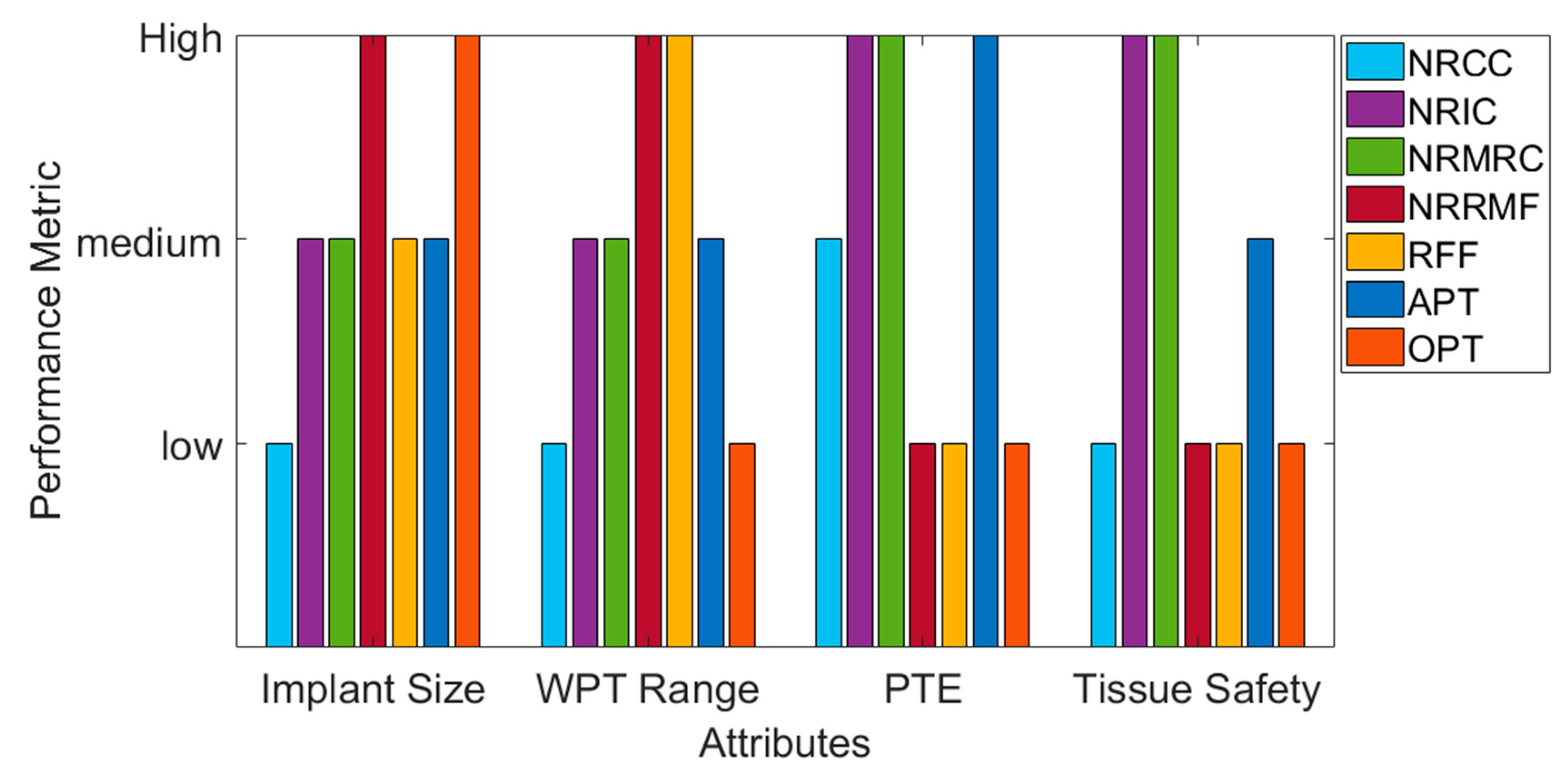
9. Performance Comparison of Various WPT Schemes
- (1)
- Typical exposure to static magnetic field must not exceed
- 8 Tesla for adults, children and infants aged > 1 month.
- 4 Tesla for infants aged ≤1 month.
- (2)
- SAR for any WPT techniques should not exceed
- 2 W/kg averaged over 10 g of tissue absorbing the most signal (Partial body SAR).
- 4 W/kg averaged over whole body (Whole body SAR).
- 3.2 W/kg averaged over head (Head SAR).
- (3)
- Rate of change of magnetic field (B)
- Any time rate of change of magnetic fields (dB/dt) should not cause discomfort or painful nerve stimulation.
10. Conclusions
Author Contributions
Funding
Conflicts of Interest
References
- Costanzo, A.; Dionigi, M.; Masotti, D.; Mongiardo, M.; Monti, G.; Tarricone, L.; Sorrentino, R. Electromagnetic Energy Harvesting and Wireless Power Transmission: A Unified Approach. Proc. IEEE 2014, 102, 1692–1711. [Google Scholar] [CrossRef]
- Garnica, J.; Chinga, R.A.; Lin, J. Wireless Power Transmission: From Far Field to Near Field. Proc. IEEE 2013, 101, 1321–1331. [Google Scholar] [CrossRef]
- Wang, G.; Liu, W.; Sivaprakasam, M.; Kendir, G.A. Design and analysis of an adaptive transcutaneous power telemetry for biomedical implants. IEEE Trans. Circuits Syst. Regul. Pap. 2005, 52, 2109–2117. [Google Scholar] [CrossRef]
- Sauer, C.; Stanacevic, M.; Cauwenberghs, G.; Thakor, N.V. Power harvesting and telemetry in CMOS for implanted devices. IEEE Trans. Circuits Syst. Regul. Pap. 2005, 52, 2605–2613. [Google Scholar] [CrossRef]
- Inanlou, F.; Ghovanloo, M. Wideband Near-Field Data Transmission Using Pulse Harmonic Modulation. IEEE Trans. Circuits Syst. I Regul. Pap. 2010, 58, 186–195. [Google Scholar] [CrossRef]
- Ghovanloo, M.; Najafi, K. A Modular 32-site wireless neural stimulation microsystem. IEEE J. Solid State Circuits 2004, 39, 2457–2466. [Google Scholar] [CrossRef]
- Sallan, J.; Villa, J.; Llombart, A.; Sanz, J. Optimal Design of ICPT Systems Applied to Electric Vehicle Battery Charge. IEEE Trans. Ind. Electron. 2009, 56, 2140–2149. [Google Scholar] [CrossRef]
- Villa, J.L.; Sallán, J.; Llombart, A.; Sanz-Osorio, J. Design of a high frequency Inductively Coupled Power Transfer system for electric vehicle battery charge. Appl. Energy 2009, 86, 355–363. [Google Scholar] [CrossRef]
- Wang, C.-S.; Covic, G.; Stielau, O. Power Transfer Capability and Bifurcation Phenomena of Loosely Coupled Inductive Power Transfer Systems. IEEE Trans. Ind. Electron. 2004, 51, 148–157. [Google Scholar] [CrossRef]
- Wang, C.-S.; Stielau, O.; Covic, G. Design Considerations for a Contactless Electric Vehicle Battery Charger. IEEE Trans. Ind. Electron. 2005, 52, 1308–1314. [Google Scholar] [CrossRef]
- Xie, L.; Shi, Y.; Hou, Y.T.; Lou, A. Wireless power transfer and applications to sensor networks. IEEE Wirel. Commun. 2013, 20, 140–145. [Google Scholar] [CrossRef]
- Kim, H.-J.; Hirayama, H.; Kim, S.; Han, K.J.; Zhang, R.; Choi, J.-W. Review of Near-Field Wireless Power and Communication for Biomedical Applications. IEEE Access 2017, 5, 21264–21285. [Google Scholar] [CrossRef]
- O’Driscoll, S.; Poon, A.; Meng, T.H. A mm-sized implantable power receiver with adaptive link compensation. In Proceedings of the 2009 IEEE International Solid-State Circuits Conference-Digest of Technical Papers, San Francisco, CA, USA, 8–12 Febuary 2009; IEEE: San Francisco, CA, USA; pp. 294–295. [Google Scholar]
- Ho, S.L.; Wang, J.; Fu, W.; Sun, M. A Comparative Study between Novel Witricity and Traditional Inductive Magnetic Coupling in Wireless Charging. IEEE Trans. Magn. 2011, 47, 1522–1525. [Google Scholar] [CrossRef]
- Kurs, A.; Karalis, A.; Moffatt, R.; Joannopoulos, J.D.; Fisher, P.; Soljačic, M. Wireless Power Transfer via Strongly Coupled Magnetic Resonances. Science 2007, 317, 83–86. [Google Scholar] [CrossRef]
- Kline, M.; Izyumin, I.; Boser, B.; Sanders, S. Capacitive power transfer for contactless charging. In Proceedings of the Conference Proceeding IEEE Applied Power Electronics Conference Exposition APEC, Phoenix, AZ, USA, 21–25 March 2011; pp. 1398–1404. [Google Scholar] [CrossRef]
- Wang, J.; Ho, S.L.; Fu, W.; Sun, M. A Finite element analysis and corresponding experiments of resonant energy transmission for wireless transmission devices using witricity. In Proceedings of the Digests of the 2010 14th Biennial IEEE Conference on Electromagnetic Field Computation, Chicago, IL, USA, 9–12 May 2010. [Google Scholar]
- Basaeri, H.; Christensen, D.B.; Roundy, S. A review of acoustic power transfer for bio-medical implants. Smart Mater. Struct. 2016, 25, 123001. [Google Scholar] [CrossRef]
- Mujeeb-U-Rahman, M.; Adalian, D.; Chang, C.-F.; Scherer, A. Optical power transfer and communication methods for wireless implantable sensing platforms. J. Biomed. Opt. 2015, 20, 95012. [Google Scholar] [CrossRef]
- Tesla, N. Apparatus for Transmitting Electrical Energy. US Patent 1,119,732, 1 December 1914. [Google Scholar]
- Green, A.W. 10 kHz inductively coupled power transfer-concept and control. In Proceedings of the Proceedings of 5th International Conference on Power Electronics and Variable-Speed Drives, London, UK, 26–28 October 1994. [Google Scholar]
- Boys, J.; Covic, G.; Green, A. Stability and control of inductively coupled power transfer systems. IEEE Proc. Electr. Power Appl. 2000, 147, 37. [Google Scholar] [CrossRef]
- Boys, J.; Hu, A.P.; Covic, G. Critical Q analysis of a current-fed resonant converter for ICPT applications. Electron. Lett. 2000, 36, 1440. [Google Scholar] [CrossRef]
- Elliott, G.; Covic, G.; Kacprzak, D.; Boys, J. A New Concept: Asymmetrical Pick-Ups for Inductively Coupled Power Transfer Monorail Systems. IEEE Trans. Magn. 2006, 42, 3389–3391. [Google Scholar] [CrossRef]
- Kissin, M.; Boys, J.; Covic, G. Interphase Mutual Inductance in Polyphase Inductive Power Transfer Systems. IEEE Trans. Ind. Electron. 2009, 56, 2393–2400. [Google Scholar] [CrossRef]
- Choi, B.; Nho, J.; Cha, H.; Ahn, T.; Choi, S. Design and Implementation of Low-Profile Contactless Battery Charger Using Planar Printed Circuit Board Windings as Energy Transfer Device. IEEE Trans. Ind. Electron. 2004, 51, 140–147. [Google Scholar] [CrossRef]
- Yungtaek, J.; Jovanovic, M.M. A contactless electrical energy transmission system for portable-telephone battery chargers. In Proceedings of the INTELEC. Twenty-Second International Telecommunications Energy Conference (Cat. No.00CH37131), Phoenix, AZ, USA, 10–14 September 2000; pp. 726–732. [Google Scholar]
- Kim, C.-G.; Seo, N.-H.; You, J.-S.; Park, J.-H.; Cho, B.H. Design of a contactless battery charger for cellular phone. IEEE Trans. Ind. Electron. 2001, 48, 1238–1247. [Google Scholar] [CrossRef]
- Hui, S.; Ho, W. A new generation of universal contactless battery charging platform for portable consumer electronic equipment. In Proceedings of the 2004 IEEE 35th Annual Power Electronics Specialists Conference (IEEE Cat. No.04CH37551), Aachen, Germany, 20–25 June 2004; pp. 638–644. [Google Scholar]
- Liu, X.; Hui, S. Simulation Study and Experimental Verification of a Universal Contactless Battery Charging Platform With Localized Charging Features. IEEE Trans. Power Electron. 2007, 22, 2202–2210. [Google Scholar] [CrossRef]
- Kindermann, M.; Schwaab, B.; Berg, M.; Frohlig, G. Longevity of dual chamber pacemakers: Device and patient related determinants. Pacing Clin. Electrophysiol. 2001, 24, 810–815. [Google Scholar] [CrossRef] [PubMed]
- Schuder, J.; Stephenson, H.; Townsend, J. High-level electromagnetic energy transfer through a closed chest wall. Inst. Radio Engrs. Int Conv. Rec. 1961, 9, 119–126. [Google Scholar]
- Ko, W.H.; Liang, S.P.; Fung, C.D.F. Design of radio-frequency powered coils for implant instruments. Med Biol. Eng. 1977, 15, 634–640. [Google Scholar] [CrossRef]
- Hochmair, E.S. System Optimization for Improved Accuracy in Transcutaneous Signal and Power Transmission. IEEE Trans. Biomed. Eng. 1984, 177–186. [Google Scholar] [CrossRef]
- Agarwal, K.; Jegadeesan, R.; Guo, Y.-X.; Thakor, N.V. Wireless Power Transfer Strategies for Implantable Bioelectronics. IEEE Rev. Biomed. Eng. 2017, 10, 136–161. [Google Scholar] [CrossRef]
- Jow, U.-M.; Ghovanloo, M. Design and Optimization of Printed Spiral Coils for Efficient Transcutaneous Inductive Power Transmission. IEEE Trans. Biomed. Circuits Syst. 2007, 1, 193–202. [Google Scholar] [CrossRef]
- Poon, A.; O’Driscoll, S.; Meng, T.H. Optimal Operating Frequency in Wireless Power Transmission for Implantable Devices. In Proceedings of the 2007 29th Annual International Conference of the IEEE Engineering in Medicine and Biology Society, Lyon, France, 23–26 August 2007; Volume 2007, pp. 5673–5678. [Google Scholar]
- Roundy, S.; Wright, P.K. A piezoelectric vibration based generator for wireless electronics. Smart Mater. Struct. 2004, 13, 1131–1142. [Google Scholar] [CrossRef]
- Goto, K.; Nakagawa, T.; Nakamura, O.; Kawata, S. An implantable power supply with an optically rechargeable lithium battery. IEEE Trans. Biomed. Eng. 2001, 48, 830–833. [Google Scholar] [CrossRef] [PubMed]
- Feng, P.; Yeon, P.; Cheng, Y.; Ghovanloo, M.; Constandinou, T. Chip-Scale Coils for Millimeter-Sized Bio-Implants. IEEE Trans. Biomed. Circuits Syst. 2018, 12, 1088–1099. [Google Scholar] [CrossRef] [PubMed]
- Lu, X.; Wang, P.; Niyato, D.; Kim, D.I.; Han, Z. Wireless Charging Technologies: Fundamentals, Standards, and Network Applications. IEEE Commun. Surv. Tutor. 2015, 18, 1413–1452. [Google Scholar] [CrossRef]
- Hui, S.Y.R.; Zhong, W.; Lee, C.K. A Critical Review of Recent Progress in Mid-Range Wireless Power Transfer. IEEE Trans. Power Electron. 2013, 29, 4500–4511. [Google Scholar] [CrossRef]
- Lee, C.K.; Zhong, W.X.; Hui, S.Y.R. Recent progress in mid-range wireless power transfer. IEEE Energy Convers. Congr. Expo. 2012, 3819–3824. [Google Scholar] [CrossRef]
- Popovic, Z. Cut the Cord: Low-Power Far-Field Wireless Powering. IEEE Microw. Mag. 2013, 14, 55–62. [Google Scholar] [CrossRef]
- Chen, Z.; Guo, B.; Yang, Y.; Cheng, C. Metamaterials-based enhanced energy harvesting: A review. Phys. B Condens. Matter. 2014, 438, 1–8. [Google Scholar] [CrossRef]
- Wang, B.; Yerazunis, W.; Teo, K.H. Wireless power transfer: Metamaterials and array of coupled resonators. Proc. IEEE 2013, 101, 1359–1368. [Google Scholar] [CrossRef]
- Chow, E.Y.; Morris, M.; Irazoqui, P. Implantable RF Medical Devices: The Benefits of High-Speed Communication and Much Greater Communication Distances in Biomedical Applications. IEEE Microw. Mag. 2013, 14, 64–73. [Google Scholar] [CrossRef]
- Keerthi, K.S.; Ilango, K.; Manjula, G.N. Study of midfield wireless power transfer for implantable medical devices. In Proceedings of the 2018 2nd International Conference on Biomedical Engineering (IBIOMED), Kuta, Indonesia, 24–26 July 2018. [Google Scholar]
- Pan, G.; Wang, L. Swallowable Wireless Capsule Endoscopy: Progress and Technical Challenges. Gastroenterol. Res. Pr. 2011, 1–9. [Google Scholar] [CrossRef]
- Basar, R.; Ahmad, M.Y.; Cho, J.; Ibrahim, F. Application of Wireless Power Transmission Systems in Wireless Capsule Endoscopy: An Overview. Sensors 2014, 14, 10929–10951. [Google Scholar] [CrossRef]
- Shadid, R.; Noghanian, S. A Literature Survey on Wireless Power Transfer for Biomedical Devices. Int. J. Antennas Propag. 2018, 2018, 1–11. [Google Scholar] [CrossRef]
- Sodagar, A.M.; Amiri, P. Capacitive coupling for power and data telemetry to implantable biomedical microsystems. In Proceedings of the 2009 4th International IEEE/EMBS Conference on Neural Engineering, Antalya, Turkey, 29 April–2 May 2009; pp. 411–414. [Google Scholar]
- Takhti, M.; Asgarian, F.; Sodagar, A.M. Modeling of a capacitive link for data telemetry to biomedical implants. In Proceedings of the 2011 IEEE Biomedical Circuits and Systems Conference (BioCAS), La Jolla, CA, USA, 10–12 November 2011; pp. 181–184. [Google Scholar]
- Hassan, A.; Sawma, C.; Hasanuzzaman, M.; Gosselin, B.; Sawan, M. Spatial carrier position modulation based multichannel capacitive link for bioelectronic implants. In Proceedings of the 2015 IEEE Biomedical Circuits and Systems Conference (BioCAS), Atlanta, GA, USA, 22–24 October 2015; IEEE: Atlanta, GA, USA; pp. 1–4. [Google Scholar]
- Jegadeesan, R.; Agarwal, K.; Guo, Y.-X.; Yen, S.-C.; Thakor, N.V. Wireless Power Delivery to Flexible Subcutaneous Implants Using Capacitive Coupling. IEEE Trans. Microw. Theory Tech. 2017, 65, 280–292. [Google Scholar] [CrossRef]
- Porzig, K.S.Y.; Brauer, H.; Toepfer, H. Biological tissues dispersivity and power loss density in transcranial magnetic stimulation. In Proceedings of the 2013 21st International Conference on Software, Telecommunications and Computer Networks - (SoftCOM 2013), Primosten, Croatia, 18–20 September 2013. [Google Scholar] [CrossRef]
- Gabriel, S.; Lau, R.W.; Gabriel, C. The dielectric properties of biological tissues: II. Measurements in the frequency range 10 Hz to 20 GHz. Phys. Med. Biol. 1996, 41, 2251–2269. [Google Scholar] [CrossRef] [PubMed]
- Land, D.V.; Gorton, A.J.; Hamilton, G. Investigations of Tissue Microwave and Thermal Properties for Combined Microwave and Thermal Modelling of Body Tissue Regions. In Radio Frequency Radiation Dosimetry and Its Relationship to the Biological Effects of Electromagnetic Fields; Springer: Dordrecht, The Netherlands, 2000; pp. 85–96. [Google Scholar]
- Narayanamoorthi, R.; Vimala Juliet, A.; Chokkalingam, B.; Padmanaban, S.; Leonowicz, Z.M. Class E Power Amplifier Design and Optimization for the Capacitive Coupled Wireless Power Transfer System in Biomedical Implants. Energies 2017, 10, 1409. [Google Scholar] [CrossRef]
- Bocan, K.N.; Mickle, M.H.; Sejdić, E. Multi-Disciplinary Challenges in Tissue Modeling for Wireless Electromagnetic Powering: A Review. IEEE Sens. J. 2017, 17, 6498–6509. [Google Scholar] [CrossRef]
- Hochmair, I.; Nopp, P.; Jolly, C.; Schmidt, M.; Schößer, H.; Garnham, C.; Anderson, I. MED-EL Cochlear Implants: State of the Art and a Glimpse Into the Future. Trends Amplif. 2006, 10, 201–219. [Google Scholar] [CrossRef]
- Patrick, J.F.; Busby, P.A.; Gibson, P.J. The Development of the Nucleus® Freedom™ Cochlear Implant System. Trends Amplif. 2006, 10, 175–200. [Google Scholar] [CrossRef]
- Wei, X.; Wang, Z.; Dai, H. A Critical Review of Wireless Power Transfer via Strongly Coupled Magnetic Resonances. Energies 2014, 7, 4316–4341. [Google Scholar] [CrossRef]
- Kim, D.-H.; Kim, J.; Park, Y.-J. Optimization and Design of Small Circular Coils in a Magnetically Coupled Wireless Power Transfer System in the Megahertz Frequency. IEEE Trans. Microw. Theory Tech. 2016, 64, 1–12. [Google Scholar] [CrossRef]
- Yang, Z.; Liu, W.; Basham, E. Inductor Modeling in Wireless Links for Implantable Electronics. IEEE Trans. Magn. 2007, 43, 3851–3860. [Google Scholar] [CrossRef]
- Abbas, S.M.; Hannan, M.; Samad, S.A.; Hussain, A. Design of Spiral Circular Coils in Wet and Dry Tissue for Bio-Implanted Micro-System Applications. Prog. Electromagn. Res. M 2013, 32, 181–200. [Google Scholar] [CrossRef]
- Khan, S.R.; Choi, G. Analysis and Optimization of Four-Coil Planar Magnetically Coupled Printed Spiral Resonators. Sensors 2016, 16, 1219. [Google Scholar] [CrossRef] [PubMed]
- Zargham, M.; Gulak, P.G. Maximum Achievable Efficiency in Near-Field Coupled Power-Transfer Systems. IEEE Trans. Biomed. Circuits Syst. 2012, 6, 228–245. [Google Scholar] [CrossRef]
- Jow, U.-M.; Ghovanloo, M. Modeling and Optimization of Printed Spiral Coils in Air, Saline, and Muscle Tissue Environments. IEEE Trans. Biomed. Circuits Syst. 2009, 3, 339–347. [Google Scholar] [CrossRef]
- Mutashar, S.; Hannan, M.; Samad, S.A.; Hussain, A. Analysis and Optimization of Spiral Circular Inductive Coupling Link for Bio-Implanted Applications on Air and within Human Tissue. Sensors 2014, 14, 11522–11541. [Google Scholar] [CrossRef]
- Harrison, R.R. Designing Efficient Inductive Power Links for Implantable Devices. IEEE Int. Symp. Circuits Syst. 2007, 1, 2080–2083. [Google Scholar] [CrossRef]
- Wu, W.; Fang, Q. Design and simulation of printed spiral coil used in wireless power transmission systems for implant medical devices. In Proceedings of the 2011 Annual International Conference of the IEEE Engineering in Medicine and Biology Society, Boston, CA, USA, 30 August–3 September 2011; Volume 2011, pp. 4018–4021. [Google Scholar]
- Mohan, S.; Hershenson, M.D.M.; Boyd, S.; Lee, T. Simple accurate expressions for planar spiral inductances. IEEE J. Solid State Circuits 1999, 34, 1419–1424. [Google Scholar] [CrossRef]
- Sadiku, N. Elements of Electromagnetics; Sounders College Press: Orlando, FL, USA, 1994; ISBN 9780511841040. [Google Scholar]
- Kiani, M.; Jow, U.-M.; Ghovanloo, M. Design and Optimization of a 3-Coil Inductive Link for Efficient Wireless Power Transmission. IEEE Trans. Biomed. Circuits Syst. 2011, 99, 1. [Google Scholar] [CrossRef]
- Kiani, M.; Ghovanloo, M. A Figure-of-Merit for Designing High-Performance Inductive Power Transmission Links. IEEE Trans. Ind. Electron. 2012, 60, 5292–5305. [Google Scholar] [CrossRef]
- Zierhofer, C.M.; Hochmair, E.S. Geometric approach for coupling enhancement of magnetically coupled coils. IEEE Trans. Biomed. Eng. 1996, 43, 708–714. [Google Scholar] [CrossRef] [PubMed]
- Atluri, S.; Ghovanloo, M. Design of a Wideband Power-Efficient Inductive Wireless Link for Implantable Biomedical Devices Using Multiple Carriers. In Proceedings of the Conference Proceedings. 2nd International IEEE EMBS Conference on Neural Engineering, Arlington, VA, USA, 16–19 March 2005; IEEE: Arlington, VA, USA, 2005; pp. 533–537. [Google Scholar]
- Khan, S.R.; Pavuluri, S.K.; Desmulliez, M.P.Y. New Analytical Model for the Characterisation of Printed Spiral Coils for Wireless Power Transfer. In Proceedings of the IEEE 12th European Conference on Antennas and Propagation (EuCAP), London, UK, 9–13 April 2018. [Google Scholar]
- Raju, S.; Wu, R.; Chan, M.; Yue, C.P. Modeling of Mutual Coupling between Planar Inductors in Wireless Power Applications. IEEE Trans. Power Electron. 2013, 29, 481–490. [Google Scholar] [CrossRef]
- Wheeler, H.A. Formulas for the Skin Effect. Proc. IRE 1942, 30, 299–311. [Google Scholar] [CrossRef]
- Kiani, M.; Ghovanloo, M. The Circuit Theory behind Coupled-Mode Magnetic Resonance-Based Wireless Power Transmission. IEEE Trans. Circuits Syst. Regul. Pap. 2012, 59, 2065–2074. [Google Scholar] [CrossRef]
- Massarini, A.; Kazimierczuk, M.; Grandi, G. Lumped parameter models for single- and multiple-layer inductors. In Proceedings of the PESC Record. 27th Annual IEEE Power Electronics Specialists Conference, Baveno, Italy, 23–27 June 1996; pp. 295–301. [Google Scholar]
- Catrysse, M.; Hermans, B.; Puers, R. An inductive power system with integrated bi-directional data-transmission. Sensors Actuators A Phys. 2004, 115, 221–229. [Google Scholar] [CrossRef]
- Rindorf, L.; Lading, L.; Breinbjerg, O. Resonantly coupled antennas for passive sensors. IEEE Sens. 2008, 1611–1614. [Google Scholar] [CrossRef]
- Bou, E.; Alarcon, E.; Gutierrez, J. A Comparison of Analytical Models for Resonant Inductive Coupling Wireless Power. Transfer. Prog. Electromagn. Res. Symp. 2012, 689–693. [Google Scholar]
- Karalis, A.; Joannopoulos, J.; Soljacić, M. Efficient wireless non-radiative mid-range energy transfer. Ann. Phys. 2008, 323, 34–48. [Google Scholar] [CrossRef]
- Moorey, C.; Holderbaum, W.; Potter, B. Investigation of High-Efficiency Wireless Power Transfer Criteria of Resonantly-Coupled Loops and Dipoles through Analysis of the Figure of Merit. Energies 2015, 8, 11342–11362. [Google Scholar] [CrossRef]
- Ju, X.; Dong, L.; Huang, X.; Liao, X. Switching Technique for Inductive Power Transfer at High-Q Regimes. IEEE Trans. Ind. Electron. 2015, 62, 2164–2173. [Google Scholar] [CrossRef]
- Yang, T.; Liang, J.; Zhao, C.; Chen, D. Analysis and design of Class-E power amplifiers at any duty ratio in frequency domain. Analog. Integr. Circuits Signal Process. 2010, 67, 149–156. [Google Scholar] [CrossRef]
- Chen, W.-T.; Chinga, R.A.; Yoshida, S.; Lin, J.; Hsu, C.-K. A 36 W Wireless Power Transfer System with 82% Efficiency for LED Lighting Applications. Trans. Jpn. Inst. Electron. Packag. 2013, 6, 32–37. [Google Scholar] [CrossRef]
- Thangasamy, V.; Kamsani, N.A.; Thiruchelvam, V.; Hamidon, M.N.; Hashim, S.J.; Bukhori, M.F.; Yusoff, Z. Wireless power transfer with on-chip inductor and class-E power amplifier for implant medical device applications. In Proceedings of the 2015 IEEE Student Conference on Research and Development (SCOReD), Kuala Lumpur, Malaysia, 13–14 December 2015; pp. 422–426. [Google Scholar] [CrossRef]
- Hayati, M.; Lotfi, A.; Kazimierczuk, M.K.; Sekiya, H. Modeling and Analysis of Class-E Amplifier with a Shunt Inductor at Sub-Nominal Operation for Any Duty Ratio. IEEE Trans. Circuits Syst. Regul. Pap. 2013, 61, 987–1000. [Google Scholar] [CrossRef]
- Liu, H.; Shao, Q.; Fang, X. Modeling and Optimization of Class-E Amplifier at Subnominal Condition in a Wireless Power Transfer System for Biomedical Implants. IEEE Trans. Biomed. Circuits Syst. 2017, 11, 35–43. [Google Scholar] [CrossRef]
- Jiang, C.; Chau, K.T.; Liu, C.; Lee, C.H. An Overview of Resonant Circuits for Wireless Power Transfer. Energies 2017, 10, 894. [Google Scholar] [CrossRef]
- Liu, M.; Fu, M.; Ma, C. Parameter Design for A 6.78-MHz Wireless Power Transfer System Based on Analytical Derivation of Class E Current-Driven Rectifier. IEEE Trans. Power. 2015, 31, 4280–4291. [Google Scholar] [CrossRef]
- Pacini, A.; Benassi, F.; Masotti, D.; Costanzo, A. Design of a RF-to-dc Link for in-body IR-WPT with a Capsule-shaped Rotation-insensitive Receiver. In Proceedings of the 2018 IEEE/MTT-S International Microwave Symposium-IMS, Philadelphia, PA, USA, 10–15 June 2018; pp. 1289–1292. [Google Scholar]
- Ghotbi, I.; Najjarzadegan, M.; Ashtiani, S.J.; Shoaei, O.; Shahabadi, M. 3-Coil orientation insensitive wireless power transfer for capsule endoscope. In Proceedings of the 2015 23rd Iranian Conference on Electrical Engineering, Tehran, Iran, 10–14 May 2015; IEEE: Tehran, Iran; pp. 1249–1254. [Google Scholar]
- Lenaerts, B.; Puers, R. An inductive power link for a wireless endoscope. Biosens. Bioelectron. 2007, 22, 1390–1395. [Google Scholar] [CrossRef]
- Carta, R.; Sfakiotakis, M.; Pateromichelakis, N.; Thoné, J.; Tsakiris, D.; Puers, R. A multi-coil inductive powering system for an endoscopic capsule with vibratory actuation. Sens. Actuators A Phys. 2011, 172, 253–258. [Google Scholar] [CrossRef]
- Pan, G.; Xin, W.; Yan, G.; Chen, J. A video wireless capsule endoscopy system powered wirelessly: Design, analysis and experiment. Meas. Sci. Technol. 2011, 22, 065802. [Google Scholar] [CrossRef]
- Mabrouki, A.; Latrach, M.; Lorrain, V. High efficiency low power rectifier design using zero bias schottky diodes. In Proceedings of the 2014 IEEE Faible Tension Faible Consommation, Monaco, 4–6 May 2014; pp. 1–4. [Google Scholar] [CrossRef]
- Sun, T.; Xie, X.; Li, G.; Gu, Y.; Deng, Y.; Wang, Z. A Two-Hop Wireless Power Transfer System with an Efficiency-Enhanced Power Receiver for Motion-Free Capsule Endoscopy Inspection. IEEE Trans. Biomed. Eng. 2012, 59, 3247–3254. [Google Scholar] [CrossRef]
- Khan, S.R.; Choi, G. High-efficiency CMOS rectifier with minimized leakage and threshold cancellation features for low power bio-implants. Microelectron. J. 2017, 66, 67–75. [Google Scholar] [CrossRef]
- Mohamed, M.M.; Fahmy, G.A.; Abdel-Rahman, A.B.; Allam, A.; Barakat, A.; Abo-Zahhad, M.; Jia, H.; Pokharel, R.K. High-Efficiency CMOS RF-to-DC Rectifier Based on Dynamic Threshold Reduction Technique for Wireless Charging Applications. IEEE Access 2018, 6, 46826–46832. [Google Scholar] [CrossRef]
- Manoufali, M.; Bialkowski, K.S.; Mohammed, B.J.; Mills, P.C.; Abbosh, A. Near-Field Inductive-Coupling Link to Power a Three-Dimensional Millimeter-Size Antenna for Brain Implantable Medical Devices. IEEE Trans. Biomed. Eng. 2018, 65, 4–14. [Google Scholar] [CrossRef] [PubMed]
- Silay, K.M.; Dehollain, C.; Declercq, M. Inductive Power Link for a Wireless Cortical Implant with Two-Body Packaging. IEEE Sens. J. 2011, 11, 2825–2833. [Google Scholar] [CrossRef]
- Mata, A.; Fleischman, A.J.; Roy, S. Characterization of Polydimethylsiloxane (PDMS) Properties for Biomedical Micro/Nanosystems. Biomed. Microdevices 2005, 7, 281–293. [Google Scholar] [CrossRef]
- Schmidt, E.M.; McIntosh, J.S.; Bak, M.J. Long-term implants of Parylene-C coated microelectrodes. Med. Biol. Eng. 1988, 26, 96–101. [Google Scholar] [CrossRef]
- Rodger, D.; Weiland, J.D.; Humayun, M.S.; Tai, Y.-C. Scalable high lead-count parylene package for retinal prostheses. Sens. Actuators B Chem. 2006, 117, 107–114. [Google Scholar] [CrossRef]
- Jegadeesan, R.; Nag, S.; Agarwal, K.; Thakor, N.V.; Guo, Y.-X. Enabling Wireless Powering and Telemetry for Peripheral Nerve Implants. IEEE J. Biomed. Heal. Inform. 2015, 19, 958–970. [Google Scholar] [CrossRef]
- Gong, C.; Liu, D.; Miao, Z.; Li, M. A Magnetic-Balanced Inductive Link for the Simultaneous Uplink Data and Power Telemetry. Sensors 2017, 17, 1768. [Google Scholar] [CrossRef]
- Kim, Y.-J.; Maeng, J.; Irazoqui, P.P. Eyeglasses-powered, contact lens-like platform with high power transfer efficiency. Biomed. Microdevices 2015, 17, 75. [Google Scholar] [CrossRef]
- Stronks, H.C.; Dagnelie, G. The functional performance of the Argus II retinal prosthesis. Expert Rev. Med. Devices 2013, 11, 23–30. [Google Scholar] [CrossRef]
- Dacruz, L.; Coley, B.F.; Dorn, J.; Merlini, F.; Filley, E.; Christopher, P.; Chen, F.K.; Wuyyuru, V.; Sahel, J.-A.; Stanga, P.; et al. The Argus II epiretinal prosthesis system allows letter and word reading and long-term function in patients with profound vision loss. Br. J. Ophthalmol. 2013, 97, 632–636. [Google Scholar] [CrossRef] [PubMed]
- Cochlear Implants for Hearing Loss|MED-EL. Available online: https://www.medel.com/uk/ (accessed on 6 January 2019).
- Faerber, J.; Gregson, R.A.; Clutton, R.E.; Khan, S.R.; Cochran, S.; Desmulliez, M.P.; Cummins, G.; Pavuluri, S.K.; Record, P.; Rodriguez, A.R.A.; et al. In Vivo Characterization of a Wireless Telemetry Module for a Capsule Endoscopy System Utilizing a Conformal Antenna. IEEE Trans. Biomed. Circuits Syst. 2018, 12, 95–105. [Google Scholar] [CrossRef] [PubMed]
- Luis, M.; Tavares, A.; Carvalho, L.S.; Lara-Santos, L.; Araújo, A.M.; De Mello, R.A. Personalizing therapies for gastric cancer: Molecular mechanisms and novel targeted therapies. World J. Gastroenterol. 2013, 19, 6383–6397. [Google Scholar] [CrossRef] [PubMed]
- A Myer, P.; Mannalithara, A.; Singh, G.; Singh, G.; Pasricha, P.J.; Ladabaum, U. Clinical and Economic Burden of Emergency Department Visits Due to Gastrointestinal Diseases in the United States. Am. J. Gastroenterol. 2013, 108, 1496–1507. [Google Scholar] [CrossRef] [PubMed]
- Nan, X.; Sullivan, C.R. An Equivalent Complex Permeability Model for Litz-Wire Windings. IEEE Trans. Ind. Appl. 2009, 45, 854–860. [Google Scholar] [CrossRef]
- Jia, Z.; Yan, G.; Jiang, P.; Wang, Z.; Liu, H. Efficiency optimization of wireless power transmission systems for active capsule endoscopes. Physiol. Meas. 2011, 32, 1561–1573. [Google Scholar] [CrossRef]
- Xin, W.; Yan, G.; Wang, W. Study of a wireless power transmission system for an active capsule endoscope. Int. J. Med. Robot. Comput. Assist. Surg. 2010, 6. [Google Scholar] [CrossRef]
- Khan, S.R.; Pavaluri, S.; Cummins, G.; Desmulliez, M.P.Y. Miniaturized 3-D Cross-Type Reciever for Wirelessly Powered Capsule Endoscopy. IEEE Trans. Microw. Theory Tech. 2018, 67, 1985–1993. [Google Scholar] [CrossRef]
- Qusba, A.; Ramrakhyani, A.K.; So, J.-H.; Hayes, G.J.; Dickey, M.D.; Lazzi, G. On the Design of Microfluidic Implant Coil for Flexible Telemetry System. IEEE Sens. J. 2014, 14, 1074–1080. [Google Scholar] [CrossRef]
- Trigui, A.; Hached, S.; Mounaim, F.; Ammari, A.C.; Sawan, M. Inductive Power Transfer System with Self-Calibrated Primary Resonant Frequency. IEEE Trans. Power Electron. 2015, 30, 1. [Google Scholar] [CrossRef]
- Assawaworrarit, S.; Yu, X.; Fan, S. Robust wireless power transfer using a nonlinear parity-time-symmetric circuit. Nature 2017, 546, 387–390. [Google Scholar] [CrossRef] [PubMed]
- Lin, J. A new IEEE standard for safety levels with respect to human exposure to radio-frequency radiation. IEEE Antennas Propag. Mag. 2006, 48, 157–159. [Google Scholar] [CrossRef]
- Sun, G.; Muneer, B.; Li, Y.; Zhu, Q. Ultracompact Implantable Design with Integrated Wireless Power Transfer and RF Transmission Capabilities. IEEE Trans. Biomed. Circuits Syst. 2018, 12, 281–291. [Google Scholar] [CrossRef] [PubMed]
- Jonah, O.; Georgakopoulos, S.V.; Tentzeris, M.M. Orientation insensitive power transfer by magnetic resonance for mobile devices. IEEE Wirel. Power Transf. 2013, 5–8. [Google Scholar] [CrossRef]
- Liu, D.; Hu, H.; Georgakopoulos, S.V. Misalignment Sensitivity of Strongly Coupled Wireless Power Transfer Systems. IEEE Trans. Power Electron. 2017, 32, 5509–5519. [Google Scholar] [CrossRef]
- Jia, Y.; Mirbozorgi, S.A.; Wang, Z.; Hsu, C.-C.; Madsen, T.E.; Rainnie, N.; Ghovanloo, M. Position and Orientation Insensitive Wireless Power Transmission for EnerCage-Homecage System. IEEE Trans. Biomed. Eng. 2017, 64, 2439–2449. [Google Scholar] [CrossRef]
- Theilmann, P.; Asbeck, P.M. An Analytical Model for Inductively Coupled Implantable Biomedical Devices with Ferrite Rods. IEEE Trans. Biomed. Circuits Syst. 2008, 3, 43–52. [Google Scholar] [CrossRef]
- Lee, W.-S.; Son, W.-I.; Oh, K.-S.; Yu, J.-W. Contactless Energy Transfer Systems Using Antiparallel Resonant Loops. IEEE Trans. Ind. Electron. 2011, 60, 350–359. [Google Scholar] [CrossRef]
- Yi, Z.; Li, M.; Muneer, B.; Zhu, Q. High-Efficiency Mid-Range Inductive Power Transfer Employing Alternative-Winding Coils. IEEE Trans. Power Electron. 2019, 34, 6706–6721. [Google Scholar] [CrossRef]
- Khan, S.R.; Pavuluri, S.K.; Desmulliez, M.P. Accurate Modeling of Coil Inductance for Near-Field Wireless Power Transfer. IEEE Trans. Microw. Theory Tech. 2018, 66, 4158–4169. [Google Scholar] [CrossRef]
- Yi, Y.; Büttner, U.; Fan, Y.; Foulds, I.G. Design and optimization of a 3-coil resonance-based wireless power transfer system for biomedical implants. Int. J. Circuit Theory Appl. 2014, 43, 1379–1390. [Google Scholar] [CrossRef]
- Ramrakhyani, A.K.; Mirabbasi, S.; Chiao, M. Design and Optimization of Resonance-Based Efficient Wireless Power Delivery Systems for Biomedical Implants. IEEE Trans. Biomed. Circuits Syst. 2010, 5, 48–63. [Google Scholar] [CrossRef] [PubMed]
- Hamam, R.E.; Karalis, A.; Joannopoulos, J.; Soljacić, M. Efficient weakly-radiative wireless energy transfer: An EIT-like approach. Ann. Phys. 2009, 324, 1783–1795. [Google Scholar] [CrossRef]
- Chen, C.-J.; Chu, T.-H.; Lin, C.-L.; Jou, Z.-C. A Study of Loosely Coupled Coils for Wireless Power Transfer. IEEE Trans. Circuits Syst. Express Briefs 2010, 57, 536–540. [Google Scholar] [CrossRef]
- Jolani, F.; Yu, Y.; Chen, Z. A Planar Magnetically Coupled Resonant Wireless Power Transfer System Using Printed Spiral Coils. IEEE Antennas Wirel. Propag. Lett. 2014, 13, 1648–1651. [Google Scholar] [CrossRef]
- Khan, S.R.; Choi, G. Optimization of planar strongly coupled wireless power transfer system for biomedical applications. Microw. Opt. Technol. Lett. 2016, 58, 1861–1866. [Google Scholar] [CrossRef]
- Li, X.; Zhang, H.; Peng, F.; Li, Y.; Yang, T.; Wang, B.; Fang, D. A Wireless Magnetic Resonance Energy Transfer System for Micro Implantable Medical Sensors. Sensors 2012, 12, 10292–10308. [Google Scholar] [CrossRef]
- Yi, Y.; Buttner, U.; Fan, Y.; Foulds, I.G. 3-Coil resonance-based wireless power transfer system for implantable electronic. IEEE Wirel. Power Transf. 2013, 230–233. [Google Scholar] [CrossRef]
- Kumar, A.; Mirabbasi, S.; Chiao, M. Resonance-based wireless power delivery for implantable devices. In Proceedings of the 2009 IEEE Biomedical Circuits and Systems Conference, Beijing, China, 26–28 November 2009; pp. 25–28. [Google Scholar]
- Mirbozorgi, S.A.; Yeon, P.; Ghovanloo, M. Robust Wireless Power Transmission to mm-Sized Free-Floating Distributed Implants. IEEE Trans. Biomed. Circuits Syst. 2017, 11, 692–702. [Google Scholar] [CrossRef]
- Ramrakhyani, A.K.; Lazzi, G. Multicoil Telemetry System for Compensation of Coil Misalignment Effects in Implantable Systems. IEEE Antennas Wirel. Propag. Lett. 2013, 11, 1675–1678. [Google Scholar] [CrossRef]
- Ng, D.C.; Williams, C.; Allen, P.; Bai, S.; Boyd, C.S.; Meffin, H.; Halpern, M.; Skafidas, E. Wireless Power Delivery for Retinal Prosthesis. In Proceedings of the 3rd Annual Conference IEEE Engineering Medicine Biology Society (EMBC 2011), Boston, MA, USA, 30 August–3 September 2011; pp. 8356–8360. [Google Scholar]
- Na, K.; Jang, H.; Ma, H.; Bien, F. Tracking Optimal Efficiency of Magnetic Resonance Wireless Power Transfer System for Biomedical Capsule Endoscopy. IEEE Trans. Microw. Theory Tech. 2014, 63, 295–304. [Google Scholar] [CrossRef]
- Ding, K.; Xie, J.; Yu, Y.; Lin, H. Wireless Power Transfer at Sub-GHz frequency for Capsule Endoscope. Prog. Electromagn. Res. C 2016, 66, 55–61. [Google Scholar] [CrossRef]
- Lee, K.; Cho, D.-H. Diversity Analysis of Multiple Transmitters in Wireless Power Transfer System. IEEE Trans. Magn. 2013, 49, 2946–2952. [Google Scholar] [CrossRef]
- Mirbozorgi, S.A.; Bahrami, H.; Sawan, M.; Gosselin, B. A Smart Multicoil Inductively Coupled Array for Wireless Power Transmission. IEEE Trans. Ind. Electron. 2014, 61, 6061–6070. [Google Scholar] [CrossRef]
- Jadidian, J.; Katabi, D. Magnetic MIMO. In Proceedings of the 20th Annual International Conference, Hongkong, China, 1 November 2014; pp. 495–506. [Google Scholar] [CrossRef]
- Xu, Q.; Wang, H.; Gao, Z.; Mao, Z.-H.; He, J.; Sun, M. A Novel Mat-Based System for Position-Varying Wireless Power Transfer to Biomedical Implants. IEEE Trans. Magn. 2013, 49, 4774–4779. [Google Scholar] [CrossRef]
- Ho, J.S.; Yeh, A.J.; Kim, S.; Poon, A.S.Y. Wireless Powering for Miniature Implantable Systems. In Neural Computation, Neural Devices, and Neural Prosthesis; Springer: New York, NY, USA, 2014; pp. 313–333. [Google Scholar]
- Ho, J.S.; Kim, S.; Poon, A.S.Y. Midfield Wireless Powering for Implantable Systems. Proc. IEEE 2013, 101, 1369–1378. [Google Scholar] [CrossRef]
- Ho, J.S.; Yeh, A.J.; Neofytou, E.; Kim, S.; Tanabe, Y.; Patlolla, B.; Beygui, R.E.; Poon, A.S.Y. Wireless power transfer to deep-tissue microimplants. Proc. Natl. Acad. Sci. USA 2014, 111, 7974–7979. [Google Scholar] [CrossRef]
- Poon, A.S.Y.; O’Driscoll, S.; Meng, T.H. Optimal Frequency for Wireless Power Transmission into Dispersive Tissue. IEEE Trans. Antennas Propag. 2010, 58, 1739–1750. [Google Scholar] [CrossRef]
- Kim, S.; Ho, J.S.; Poon, A.S.Y. Wireless Power Transfer to Miniature Implants: Transmitter Optimization. IEEE Trans. Antennas Propag. 2012, 60, 4838–4845. [Google Scholar] [CrossRef]
- Gabriel, S.; Lau, R.W.; Gabriel, C. The dielectric properties of biological tissues: III. Parametric models for the dielectric spectrum of tissues. Phys. Med. Biol. 1996, 41, 2271–2293. [Google Scholar] [CrossRef] [PubMed]
- Tanabe, Y.; Ho, J.S.; Liu, J.; Liao, S.-Y.; Zhen, Z.; Hsu, S.; Shuto, C.; Zhu, Z.-Y.; Ma, A.; Vassos, C.; et al. High-performance wireless powering for peripheral nerve neuromodulation systems. PLoS ONE 2017, 12, e0186698. [Google Scholar] [CrossRef] [PubMed]
- Das, R.; Yoo, H. A Multiband Antenna Associating Wireless Monitoring and Nonleaky Wireless Power Transfer System for Biomedical Implants. IEEE Trans. Microw. Theory Tech. 2017, 65, 2485–2495. [Google Scholar] [CrossRef]
- A Bercich, R.; Duffy, D.R.; Irazoqui, P.P. Far-Field RF Powering of Implantable Devices: Safety Considerations. IEEE Trans. Biomed. Eng. 2013, 60, 2107–2112. [Google Scholar] [CrossRef]
- Varghese, B.J.; Bobba, P.B.; Kavitha, M. Effects of coil misalignment in a four coil implantable wireless power transfer system. In Proceedings of the 2016 IEEE 7th Power India International Conference (PIICON), Bikaner, India, 25–27 Novomber 2016. [Google Scholar] [CrossRef]
- Falkenstein, E.; Roberg, M.; Popovic, Z. Low-Power Wireless Power Delivery. IEEE Trans. Microw. Theory Tech. 2012, 60, 2277–2286. [Google Scholar] [CrossRef]
- Agarwal, K.; Mishra, T.; Karim, M.F.; Nasimuddin; Chuen, M.O.L.; Guo, Y.X.; Panda, S.K. Highly efficient wireless energy harvesting system using metamaterial based compact CP antenna. In Proceedings of the 2013 IEEE MTT-S International Microwave Symposium Digest (MTT), Montreal, QC, Canada, 17–22 June 2012; pp. 1–4. [Google Scholar]
- Shinohara, N.; Matsumoto, H. Experimental study of large rectenna array for microwave energy transmission. IEEE Trans. Microw. Theory Tech. 1998, 46, 261–268. [Google Scholar] [CrossRef]
- Xia, M.; Aïssa, S. On the Efficiency of Far-Field Wireless Power Transfer. IEEE Trans. Signal Process. 2015, 63, 2835–2847. [Google Scholar] [CrossRef]
- Liu, C.; Guo, Y.-X.; Xiao, S. Wireless data telemetry and power transfer for biomedical applications. In Proceedings of the 2014 IEEE MTT-S International Microwave Workshop Series on RF and Wireless Technologies for Biomedical and Healthcare Applications (IMWS-Bio2014), London, UK, 8–10 December 2014; pp. 1–3. [Google Scholar] [CrossRef]
- Liu, C.; Guo, Y.-X.; Sun, H.; Xiao, S. Design and Safety Considerations of an Implantable Rectenna for Far-Field Wireless Power Transfer. IEEE Trans. Antennas Propag. 2014, 62, 5798–5806. [Google Scholar] [CrossRef]
- Agarwal, K.; Guo, Y.-X.; Kush, A. Interaction of electromagnetic waves with humans in wearable and biomedical implant antennas. In Proceedings of the 2015 Asia-Pacific Symposium on Electromagnetic Compatibility (APEMC), Taipei, Taiwan, 26–29 May 2015; pp. 154–157. [Google Scholar] [CrossRef]
- Understanding the FCC Regulations for Low Power, Non-Licensed Transmitters; CreateSpace Independent Publishing Platform: Columbia, MD, USA, 1996.
- Rudge, A. Antenna Theory and Design. Electron. Power 1982, 28, 267. [Google Scholar] [CrossRef]
- Pozar, D. Microwave Engineering Fourth Edition; Wiley: Hoboken, NJ, USA, 2005; ISBN 9780470631553. [Google Scholar]
- Chu, L.J. Physical Limitations of Omni-Directional Antennas. J. Appl. Phys. 1948, 19, 1163. [Google Scholar] [CrossRef]
- Volakis, J.; Chen, C.-C.; Fujimoto, K. Small Antennas: Miniaturization Techniques & Applications; McGraw-Hill Professional Publishing: New York, NY, USA, 2010; ISBN 0071625542. [Google Scholar]
- Gustafsson, M.; Tayli, D.; Cismasu, M. Physical Bounds of Antennas; Springer: Singapore, 2015; pp. 1–32. [Google Scholar]
- Collin, R.; Rothschild, S. Evaluation of antenna Q. IRE Trans. Antennas Propag. 1964, 12, 23–27. [Google Scholar] [CrossRef]
- McLean, J.S. A re-examination of the fundamental limits on the radiation Q of electrically small antennas. IEEE Trans. Antennas Propag. 1996, 44, 672. [Google Scholar] [CrossRef]
- Yaghjian, A.D.; Best, S.R. Impedance, bandwidth, and Q of antennas. In Proceedings of the IEEE Antennas and Propagation Society International Symposium. Digest. Held in Conjunction with: USNC/CNC/URSI North American Radio Sci. Meeting (Cat. No.03CH37450), Columbus, OH, USA, 22–27 June 2003; Volume 1, pp. 501–504. [Google Scholar]
- Nyberg, D.; Kildal, P.-S.; Carlsson, J. Radiation Q and radiation efficiency of wideband small antennas and their relation to bandwidth and cut-off of spherical modes. In Proceedings of the 2nd European Conference on Antennas and Propagation (EuCAP 2007), Edinburgh, UK, 11–16 November 2007; Institution of Engineering and Technology: London, UK, 2007; p. 133. [Google Scholar]
- Chow, E.Y.; Chlebowski, A.L.; Chakraborty, S.; Chappell, W.J.; Irazoqui, P.P. Fully Wireless Implantable Cardiovascular Pressure Monitor Integrated with a Medical Stent. IEEE Trans. Biomed. Eng. 2010, 57, 1487–1496. [Google Scholar] [CrossRef] [PubMed]
- Chien, T.-F.; Cheng, C.-M.; Yang, H.-C.; Jiang, J.-W.; Luo, C.-H. Development of Nonsuperstrate Implantable Low-Profile CPW-Fed Ceramic Antennas. IEEE Antennas Wirel. Propag. Lett. 2010, 9, 599–602. [Google Scholar] [CrossRef]
- Huang, F.-J.; Lee, C.-M.; Chang, C.-L.; Chen, L.-K.; Yo, T.-C.; Luo, C.-H. Rectenna Application of Miniaturized Implantable Antenna Design for Triple-Band Biotelemetry Communication. IEEE Trans. Antennas Propag. 2011, 59, 2646–2653. [Google Scholar] [CrossRef]
- Liu, C.; Guo, Y.-X.; Xiao, S. A Hybrid Patch/Slot Implantable Antenna for Biotelemetry Devices. IEEE Antennas Wirel. Propag. Lett. 2013, 11, 1646–1649. [Google Scholar] [CrossRef]
- Xu, L.-J.; Guo, Y.-X.; Wu, W. Miniaturized Dual-Band Antenna for Implantable Wireless Communications. IEEE Antennas Wirel. Propag. Lett. 2014, 13, 1160–1163. [Google Scholar] [CrossRef]
- Liu, C.; Guo, Y.-X.; Xiao, S. Capacitively Loaded Circularly Polarized Implantable Patch Antenna for ISM Band Biomedical Applications. IEEE Trans. Antennas Propag. 2014, 62, 2407–2417. [Google Scholar] [CrossRef]
- Marnat, L.; Ouda, M.H.; Arsalan, M.; Salama, K.N.; Shamim, A. On-Chip Implantable Antennas for Wireless Power and Data Transfer in a Glaucoma-Monitoring SoC. IEEE Antennas Wirel. Propag. Lett. 2013, 11, 1671–1674. [Google Scholar] [CrossRef]
- Umay, I.; Fidan, B.; Barshan, B. Localization and Tracking of Implantable Biomedical Sensors. Sensors 2017, 17, 583. [Google Scholar] [CrossRef]
- Masotti, D.; Costanzo, A.; Rizzoli, V. Smart Wireless Power Transfer Operated by Time-Modulated Arrays via a Two-Step Procedure. Int. J. Antennas Propag. 2015, 2015, 1–11. [Google Scholar] [CrossRef]
- Safar, M.A.; Al-Zayed, A.S. A Novel Three-Dimensional Beamforming Antenna Array for Wireless Power Focusing. Math. Probl. Eng. 2016, 2016, 1–8. [Google Scholar] [CrossRef]
- Denisov, A.; Yeatman, E. Ultrasonic vs. Inductive Power Delivery for Miniature Biomedical Implants. In Proceedings of the 2010 International Conference on Body Sensor Networks, Washington, DC, USA, 7–9 June 2010; pp. 84–89. [Google Scholar]
- Christensen, D.B.; Roundy, S. Ultrasonically powered piezoelectric generators for bio-implantable sensors: Plate versus diaphragm. J. Intell. Mater. Syst. Struct. 2015, 27, 1092–1105. [Google Scholar] [CrossRef]
- Sanni, A.; Vilches, A. Powering low-power implants using PZT transducer discs operated in the radial mode. Smart Mater. Struct. 2013, 22, 115005. [Google Scholar] [CrossRef]
- Ozeri, S.; Shmilovitz, D.; Singer, S.; Wang, C.-C. Ultrasonic transcutaneous energy transfer using a continuous wave 650 kHz Gaussian shaded transmitter. Ultrasonics 2010, 50, 666–674. [Google Scholar] [CrossRef]
- Ozeri, S.; Shmilovitz, D. Ultrasonic transcutaneous energy transfer for powering implanted devices. Ultrasonics 2010, 50, 556–566. [Google Scholar] [CrossRef]
- Seo, D.; Carmena, J.M.; Rabaey, J.M.; Maharbiz, M.M.; Alon, E. Model validation of untethered, ultrasonic neural dust motes for cortical recording. J. Neurosci. Methods 2015, 244, 114–122. [Google Scholar] [CrossRef]
- Song, S.H.; Kim, A.; Ziaie, B. Omni-Directional Ultrasonic Powering for Millimeter-Scale Implantable Devices. IEEE Trans. Biomed. Engg. 2015, 62, 2717–2723. [Google Scholar] [CrossRef]
- Sherrit, S.; Leary, S.P.; Dolgin, B.P.; Bar-Cohen, Y. Comparison of the Mason and KLM equivalent circuits for piezoelectric resonators in the thickness mode. In Proceedings of the 1999 IEEE Ultrasonics Symposium. Proceedings. International Symposium (Cat. No.99CH37027), Caesars Tahoe, NV, USA, 17–20 October 1999; pp. 921–926. [Google Scholar]
- Nakamura, K. Ultrasonic Transducers: Materials and Design for Sensors, Actuators and Medical Applications; Woodhead Publishing: Cambridge, UK, 2012; ISBN 9780857096302. [Google Scholar]
- Mazzilli, F.; Thoppay, P.E.; Praplan, V.; Dehollain, C. Ultrasound energy harvesting system for deep implanted-medical-devices (IMDs). In Proceedings of the 2012 IEEE International Symposium on Circuits and Systems, Seoul, Korea, 20–23 May 2012; pp. 2865–2868. [Google Scholar]
- Mazzilli, F.; Lafon, C.; Dehollain, C. A 10.5 cm Ultrasound Link for Deep Implanted Medical Devices. IEEE Trans. Biomed. Circuits Syst. 2014, 8, 738–750. [Google Scholar] [CrossRef]
- Sanni, A.; Vilches, A.; Toumazou, C. Inductive and Ultrasonic Multi-Tier Interface for Low-Power, Deeply Implantable Medical Devices. IEEE Trans. Biomed. Circuits Syst. 2012, 6, 297–308. [Google Scholar] [CrossRef]
- Kim, A.; Powell, C.; Ziaie, B. An Implantable Pressure Sensing System with Electromechanical Interrogation Scheme. IEEE Trans. Biomed. Eng. 2014, 61, 2209–2217. [Google Scholar] [CrossRef] [PubMed]
- Zhou, J.; Kim, A.; Ziaie, B. An ultrasonically controlled power management system for implantable biomedical devices. In Proceedings of the 2015 IEEE Biomedical Circuits and Systems Conference (BioCAS), Atlanta, GA, USA, 22–24 October 2015; pp. 1–4. [Google Scholar] [CrossRef]
- Charthad, J.; Chang, T.C.; Liu, Z.; Sawaby, A.; Weber, M.J.; Baker, S.; Gore, F.; Felt, S.; Arbabian, A. Amm-Sized Wireless Implantable Device for Electrical Stimulation of Peripheral Nerves. IEEE Trans. Biomed. Circuits Syst. 2018, 12, 257–270. [Google Scholar] [CrossRef] [PubMed]
- Maleki, T.; Cao, N.; Song, S.H.; Kao, C.; Ko, S.-C.; Ziaie, B. An Ultrasonically Powered Implantable Micro-Oxygen Generator (IMOG). IEEE Trans. Biomed. Eng. 2011, 58, 3104–3111. [Google Scholar] [CrossRef]
- Zhou, J.; Kim, A.; Song, S.H.; Ziaie, B. An ultrasonically powered implantable micro-light source for localized photodynamic therapy. In Proceedings of the 18th International Conference Solid-State Sensors, Actuators Microsystems, TRANSDUCERS 2015, Anchorage, AK, USA, 21–25 June 2015; pp. 876–879. [Google Scholar] [CrossRef]
- Li, J.; Nie, Z.; Liu, Y.; Wang, L.; Hao, Y. Characterization of In-Body Radio Channels for Wireless Implants. IEEE Sens. J. 2017, 17, 1528–1537. [Google Scholar] [CrossRef]
- Duck, F. Ultrasound in medicine. Ultrasonics 1986, 24, 294. [Google Scholar] [CrossRef]
- Hoskins, P.; Martin, K.; Thrush, A. Diagnostic Ultrasound: Physics and Equipment; Cambridge University Press: Cambridge, UK, 2010; ISBN 9780521757102. [Google Scholar]
- Cotte, B.; Lafon, C.; Dehollain, C.; Chapelon, J.Y. Theoretical Study for Safe and Efficient Energy Transfer to Deeply Implanted Devices using Ultrasound. IEEE Trans. Ultra., Fero. Freq. Cont. 2012, 59, 1674–1685. [Google Scholar] [CrossRef]
- Thompson, W.R.; Yen, S.S.; Rubin, J. Vibration therapy: Clinical applications in bone. Curr. Opin. Endocrinol. Diabetes Obes. 2014, 21, 447–453. [Google Scholar] [CrossRef]
- Raavi, S.; Arigong, B.; Zhou, R.; Jung, S.; Jin, M.; Zhang, H.; Kim, H. An optical wireless power transfer system for rapid charging. In Proceedings of the 2013 Texas Symposium on Wireless and Microwave Circuits and Systems (WMCS), Waco, TX, USA, 4–5 April 2013; pp. 1–4. [Google Scholar] [CrossRef]
- Dregely, D.; Lindfors, K.; Lippitz, M.; Engheta, N.; Totzeck, M.; Giessen, H. Imaging and steering an optical wireless nanoantenna link. Nat. Commun. 2014, 5, 4354. [Google Scholar] [CrossRef]
- Pani, C.; Ray, O.; Ghosh, A.; Qadir, Z.; Sarkar, M.; Reja, W. Wireless power transfer using free space photonics. In Proceedings of the 2016 2nd International Conference on Advances in Computing, Communication, & Automation (Fall), Bareilly, India, 30 September–1 October 2016; pp. 1–5. [Google Scholar] [CrossRef]
- Fakidis, J.; Videv, S.; Kucera, S.; Claussen, H.; Haas, H. Indoor Optical Wireless Power Transfer to Small Cells at Nighttime. J. Light. Technol. 2016, 34, 3236–3258. [Google Scholar] [CrossRef]
- Sze, S.M.; Ng, K.K. Physics of Semiconductor Devices; John Wiley & Sons, Inc.: Hoboken, NJ, USA, 2006; ISBN 9780470068328. [Google Scholar]
- Silay, K.M.; Dehollain, C.; Declercq, M. A Closed-Loop Remote Powering Link for Wireless Cortical Implants. IEEE Sens. J. 2013, 13, 3226–3235. [Google Scholar] [CrossRef]
- Zhang, X.; Ho, S.L.; Fu, W. A Hybrid Optimal Design Strategy of Wireless Magnetic-Resonant Charger for Deep Brain Stimulation Devices. IEEE Trans. Magn. 2013, 49, 2145–2148. [Google Scholar] [CrossRef]
- Węglarski, M.; Jankowski-Mihułowicz, P. Factors Affecting the Synthesis of Autonomous Sensors with RFID Interface. Sensors 2019, 19, 4392. [Google Scholar] [CrossRef] [PubMed]
- Memon, M.L.; Saxenab, N.; Roy, A.; Shin, D.R. Backscatter Communications: Inception of the Battery-Free Era—A Comprehensive Survey. Electronics 2019, 8, 129. [Google Scholar] [CrossRef]


| Layout | C1 | C2 | C3 | C4 |
|---|---|---|---|---|
| Circle | 1.27 | 2.07 | 0.18 | 0.13 |
| Octagonal | 1.09 | 2.23 | 0.00 | 0.17 |
| Hexagonal | 1.07 | 2.29 | 0.00 | 0.19 |
| Square | 1.00 | 2.46 | 0.00 | 0.20 |
| Powering Scheme | Year/Ref | Implant Type | Implant WPTRX Size | Distance (mm) | Frequency (MHz) | Input Power (W) | PTE (%) | Test Model | SAR (W/kg) | Remarks | Maturity for IMD |
|---|---|---|---|---|---|---|---|---|---|---|---|
| NRCC | 2017/[53] | Generic | 20 mm × 20 mm | 7 | 100–150 | 1 | 56 | non-human primate cadaver | 8.02 | TX and RX are large. Separation distance and tissue safety low. | Low |
| NRIC | 2018/[40] | Brain | Diameter: 4 mm (around-CMOS) | 11 | 318.8 | 0.01 | 3.05 | Lamb ribs | 0.155 | Acceptable PTE for medium separation distance. Wide range of application. Tissue safety is achieved. The circuit for TX and RX is easily implementable and cheap. | High(implemented in some commercial IMDs) |
| 2017/[106] | Brain | Volume: 0.9 mm3, Gap: 0.1 mm | 3 | 402 | 0.082 | 0.08 | Piglet | 1.97 | |||
| 2015/[111] | Peripheral Nerve | 20 | 5 | 1 | 0.18 | 65.8 | Rat stomach | 0.1 | |||
| 2017/[112] | Ocular | Diameter: 20 mm | 8 (Max. 40 mm distance) | 2 | - | 60 (5% PTE for 40 mm) | Beef muscle | 0.66 | |||
| 2015/[113] | Ocular | Diameter: 10 mm | 20 | 13.56 | 2 | 17.5 | Pig eye | 0.021 | |||
| 2007/[99] | Capsule | 10 mm × 13 mm | - | 1 | - | 1 | Air | 0.32 | |||
| 2010/[122] | Capsule | 10 mm × 12 mm | - | 0.4 | - | 1.2 | Air | 0.329 | |||
| 2011/[121] | Capsule | 11.5 mm × 11.5 mm | 200 | 0.218 | - | 5.5 | Air | 8 | |||
| 2012/[103] | Capsule | Diameter:11 mm | - | 13.56 | 8 | 3.04 | Phantom | 0.1 | |||
| NRMRC | 2017/[145] | Brain | Diameter: 1.2 mm | 16 | 60 | - | 3 | Fresh lamb head | Less than 1.6 | RX size is smaller than NRIC and the separation distance is higher. Tissue safety is within the limit. Better impedance matching than NRIC. | High (possible to implement in commercial IMDs) |
| 2012/[146] | Ocular | Diameter: 15 mm | 10 | 3.37 | - | 62.5 | Air | - | |||
| 2011/[147] | Ocular | Diameter: 15 mm | 5 | 6.78 | - | 8.8 | Human head | - | |||
| 2015/[148] | Capsule | Diameter: 9 mm | 70 | 16.47 | 150 | 0.7 | Chopped pig tissue | 1.74 | |||
| 2016/[149] | Capsule | 15 mm × 7 mm × 6 mm | 50 | 433.9 | 1 | 1.21 | Duck intestine | 2.54 | |||
| NRRMF | 2014/[156] | Cardiac | Diameter: 2 mm | 50 | 1600 | 0.5 | 0.04 | Epicardium of rabbit | 0.89 | Higher separation distance for smaller RX. PTE is low. Tissue safety is alarming. | Medium (more research required for IMD) |
| 2017/[160] | Peripheral Nerve | 20 mm | 15 | 2400 | 0.18 | 20 | Right neck of pig | 2 | |||
| 2017/[161] | Capsule | Printed on capsule | - | 402–405 | - | 0.08 | A phantom containing a porcine heart | - | |||
| RFF | 2011/[183] | Generic | 10 mm × 10 mm × 2 mm | - | 433 | 0.005 | 15 | Minced pork of 65 mm × 92 mm × 50 mm | 1.6 | Higher distance. Lower PTE and tissue safety is alarming. | Medium |
| 2010/[181] | Cardiac | - | 100 | 3700 | 3.2 | - | Chest cavity of porcine | 2.2898 | |||
| APT | 2011/[206] | Micro-oxygen generator | 5 mm2 | 30 mm | 2.15 | - | - | Pancreatic tumor of athymic mice | - | Promising WPT technique with smaller RX and large separation distance compared to NRIC and NRMRC. Tissue safety study is necessary. | High (more research required to implement in commercial IMDs) |
| 2014/[203] | Bladder pressure | 20 mm × 2 mm × 0.38 mm | 100 | 0.00035 | - | 1.4 × 10⁻⁴ | Pig bladder | - | |||
| 2015/[207] | Photo dynamic therapy | 2 mm × 2 mm × 2 mm | 10 | 0.672 | - | - | Porcine tissue | - | |||
| 2018/[205] | Peripheral nerves | - | 105 | 1.314 | - | - | Frog static nerve | - | |||
| OPT | 2015/[19] | Generic | 0.5 mm × 0.5 mm | 3 | - | - | 0.4 | Chicken skin | - | Early stage in research. | Low |
© 2020 by the authors. Licensee MDPI, Basel, Switzerland. This article is an open access article distributed under the terms and conditions of the Creative Commons Attribution (CC BY) license (http://creativecommons.org/licenses/by/4.0/).
Share and Cite
Khan, S.R.; Pavuluri, S.K.; Cummins, G.; Desmulliez, M.P.Y. Wireless Power Transfer Techniques for Implantable Medical Devices: A Review. Sensors 2020, 20, 3487. https://doi.org/10.3390/s20123487
Khan SR, Pavuluri SK, Cummins G, Desmulliez MPY. Wireless Power Transfer Techniques for Implantable Medical Devices: A Review. Sensors. 2020; 20(12):3487. https://doi.org/10.3390/s20123487
Chicago/Turabian StyleKhan, Sadeque Reza, Sumanth Kumar Pavuluri, Gerard Cummins, and Marc P. Y. Desmulliez. 2020. "Wireless Power Transfer Techniques for Implantable Medical Devices: A Review" Sensors 20, no. 12: 3487. https://doi.org/10.3390/s20123487
APA StyleKhan, S. R., Pavuluri, S. K., Cummins, G., & Desmulliez, M. P. Y. (2020). Wireless Power Transfer Techniques for Implantable Medical Devices: A Review. Sensors, 20(12), 3487. https://doi.org/10.3390/s20123487