Article

Modeling and Research on Power System of Distributed Sensor Networks for Long Streamers in Marine Seismic Exploration

1
Department of Modern Physics, University of Science and Technology of China, Hefei 230026, China
2
State Key Laboratory of Particle Detection and Electronics, University of Science and Technology of China, Hefei 230026, China
*
Author to whom correspondence should be addressed.
Sensors 2020, 20(1), 28; https://doi.org/10.3390/s20010028
Submission received: 27 October 2019 / Revised: 12 December 2019 / Accepted: 17 December 2019 / Published: 19 December 2019
(This article belongs to the Special Issue Sensing in Oil and Gas Applications)

Abstract

:
The electric power system plays an important role in sensor networks. In the marine seismic exploration streamer system (MSESS), an underwater power system transmits high-voltage direct current to all nodes in the streamer through a daisy chain structure. As offshore oil exploration develops toward deep water, it is necessary to study long streamers with large-scale sensor networks for deep water exploration. When the length of a streamer is increased to a certain value, the output current of the power supply increases sharply. This results in the activation of the overcurrent protection and the power supply shuts down. This paper puts forward an accurate model for an underwater power system applied to MSESS. Using the Newton iteration algorithm and a reverse algorithm, equations established by the model are solved and laboratory test results are used to verify the accuracy of the model. Based on simulation and analysis of the model, we explain why the power system crashes when the streamer is too long. Software that can quickly calculate the maximum number of nodes (the maximum length with which the system works normally) is developed and it is significant for the design of MSESS. The method of research could also be applied to relevant work such as large-scale sensor networks with daisy-chaining power supply in land seismic exploration.

1. Introduction

In recent years, new oil and gas resources have come mainly from the sea, particularly from deep water and ultra-deep water areas [1,2,3,4]. As marine oil and gas exploration gradually develops into deep water areas, the exploration targets are gradually moving from the ocean surface to medium depths, which puts more stringent requirements on seismic exploration technology [5,6,7].
The basic method of marine seismic exploration is to create artificial seismic waves through air guns in seawater. Sensor networks in the streamer collect seismic waves reflected from the submarine strata. After being processed, the original record information is used to infer the underground structure of the subsea strata [8,9,10,11,12]. The working process is shown in Figure 1. For the effective exploration and development of oil and gas in deep water environments, it is necessary to study long streamers. The increase in streamer length makes it difficult to provide the data acquisition station (DAS) with an effective power supply.
Large-scale sensor networks and poor working conditions at sea necessitate a system with a convenient and stable power supply [13,14,15]. Most of the exploration instruments on the market adopt a daisy chain structure to transfer high voltage to single nodes. Direct current (DC)-to-DC converters transform high voltage to low voltage, which powers the acquisition station [16,17]. In actual operation, these kinds of power system normally work in mesoscale sensor networks. As the quantity of data acquisition nodes increases, power consumption appears to increase in a non-linear fashion, and a rapid increase in current causes the system crash. For instance, the maximum length of the streamer developed by the China National Offshore Oil Corp (CNOOC) named “HQI-Seis” can reach only 7 km with a tracking spacing of 3.125 m [18,19,20]. When one more node is added, the output current of the power supply on the geophysical survey vessel increases sharply. Once this happens, the overcurrent protection function of the power supply engages and the power supply disconnects the output. The inability of “HQI-Seis” to support a longer length has confused designers.
In order to study long streamers and analyze the inability of the system to support infinite nodes, we design a power dissipation model with line loss for marine seismic exploration sensor networks. Non-linear equations established by the model are solved by Newton iteration algorithm and reverse algorithm. Simulation and testing verify the accuracy of the model. Based on the study of the model, the reason why the marine seismic exploration streamer system (MSESS) can only support a finite number of nodes is found. To provide guidance for the design of the power system, software is developed to predict the maximum number of nodes under specific conditions.

2. Structure of Marine Seismic Exploration Streamer (MSESS)

Marine seismic exploration sensor networks are composed of several towlines. The internal power supply structure of one single towing data acquisition system is presented in Figure 2. There are multiple DASs in the streamer. Every two DASs is 100 m apart and DASs are responsible for collecting signals from a total of 16 sensors. The sensors include piezoelectric ceramic sensors and microelectro mechanical systems (MEMS) sensors, which receive seismic wave signals reflected by the strata.
The power system of MSESS is high-voltage direct current output in a daisy chain distribution pattern. A low-resistance power cable with nodes spaced 100 m apart is used to transfer electricity. The node is responsible for data acquisition and transmission. The first node (fiber package) is located 500 m from the power supply on the geophysical survey vessel, which utilizes optical fiber to transmit data. DASs use twisted-pair cables to transmit data. On each node, a DC-to-DC converter is used to transform high voltage on the power cable to usable voltage for the DASs. Figure 3 illustrates the structure of the power system.

3. Power Supply Model

In this section, we set up a model to analyze voltage distribution and current distribution on the power cables. According to the model, non-linear equations are established and two algorithms to solve the equations are proposed. We give a detailed description about how to set up the model in Section 3.1. The algorithms are detailed in Section 3.2.

3.1. Setting Up the Model

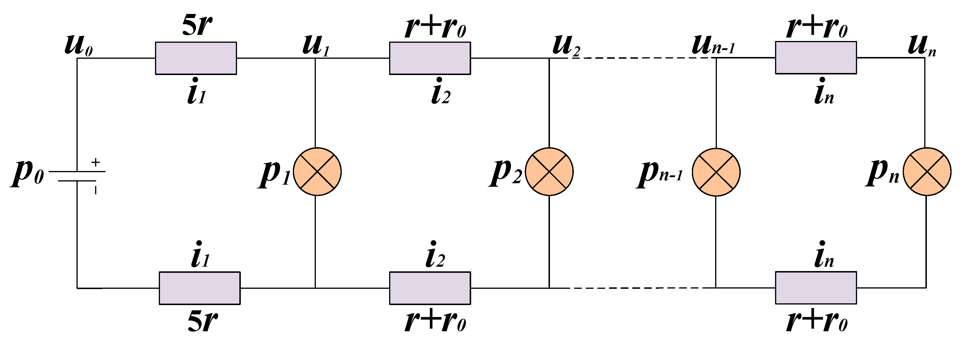
According to the architecture of the power system, we create a model to analyze system power consumption and voltage drop on the power cables. In Figure 4, (1, 2, …, n) represent the number of nodes. The variable u0 is the high-voltage direct current output (HVO) and u1~un are the voltage on the power cable at the terminal of each node. The variable r is the resistance of the 100 m power cable and r0 is the turn-on resistance of the metal-oxide-semiconductor field effect transistor (MOSFET) switch, which enables the power supply of the next node. The MOSFET switch also exists in the return path. The variables i1~in are the current on each 100 m power cable. The variable p0 stands for the power dissipation of the whole system and p1~pn represent the power consumption of each node, including the DC-to-DC converter and the DAS. The variable p1 is the power consumption of the fiber package, which is different from DAS.
On the basis of the Kirchhoff voltage law, Equation (1) is acquired:
u n 1 = u n + ( r + r 0 ) i n + ( r + r 0 ) i n = u n + 2 ( r + r 0 ) i n = u n + ( R + R 0 ) i n
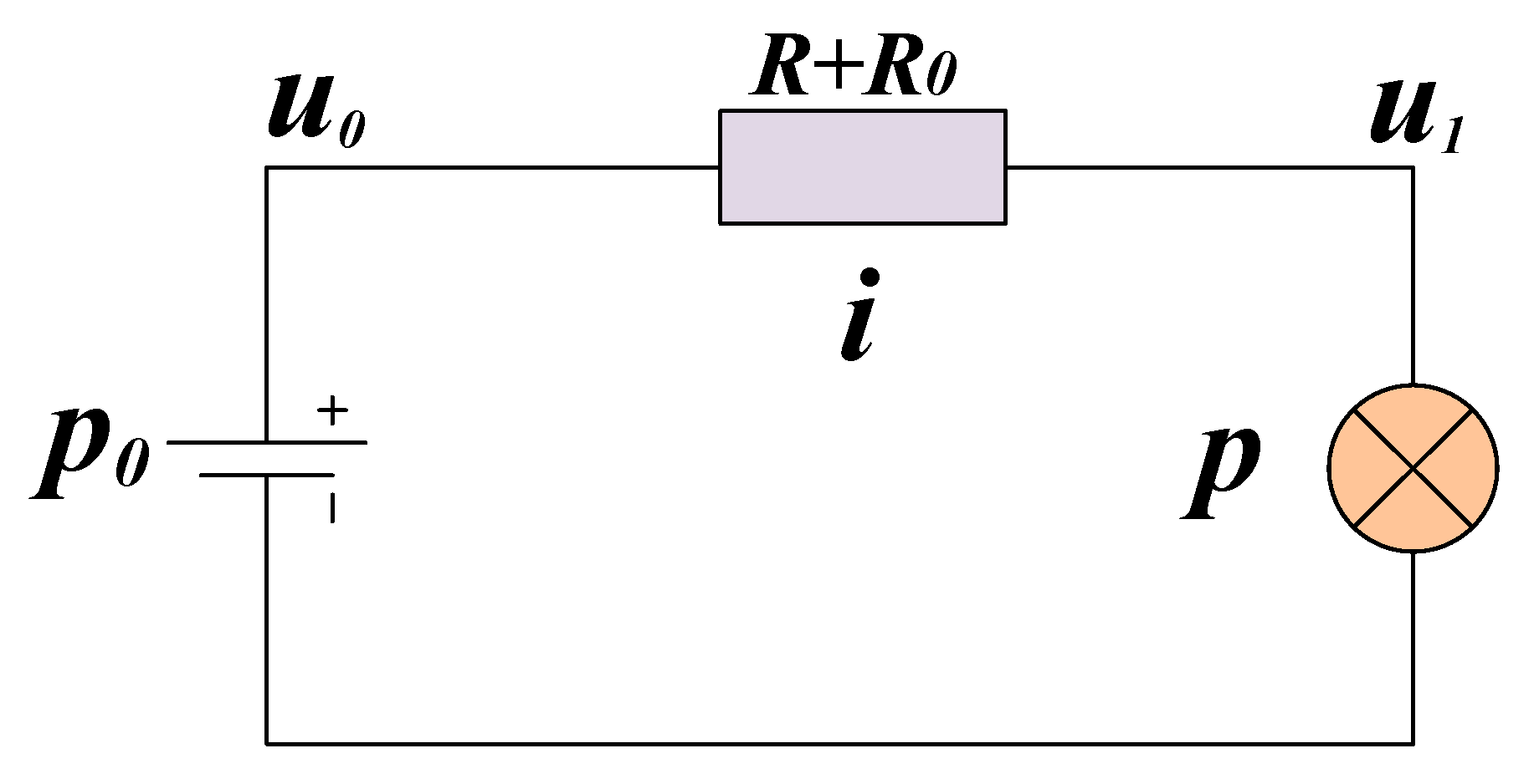
The model can be simplified as shown in Figure 5. R represents the impedance of a loop of two 100 m power cables while R0 is the trigger resistance of the loop switch. We used this model to calculate the power consumption (p0) and voltage drop on the power cable (u1~un).
Using the Kirchhoff voltage law and the Kirchhoff current law, we can derive Equations (2) and (3). Equations (4) can be derived by combining Equations (2) and (3). The variable p0 is analyzed as described in Equation (5). In Equation (5), p0 represents the power dissipation of the whole system and it consists of two parts. One is line loss on power cable, which corresponds to the first part of Equation (5) ( ( u 0 u 1 ) 2 5 R + ( u 1 u 2 ) 2 R + R 0 + + ( u n 1 u n ) 2 R + R 0 ). The other is power consumption of DASs, which corresponds to the last part of Equation (5) ( i = 1 n p i ). The next section will discuss methods for solving these equations.
{ u 0 = 5 i 1 R + u 1 u 1 = i 2 ( R + R 0 ) + u 2 u n 1 = i n   ( R + R 0 ) + u n
{ i 1 = i 2 + p 1 u 1 i 2 = i 3 + p 2 u 2 i n 1 = i n + p n 1 u n 1 i n = p n u n
{ p 1 u 1 + u 1 u 2 R + R 0 = u 0 u 1 5 R p 2 u 2 + u 2 u 3 R + R 0 = u 1 u 2 R + R 0 p n 1 u n 1 + u n 1 u n R + R 0 u n 2 u n 1 R + R 0 p n u n = u n 1 u n R + R 0
p 0 = ( u 0 u 1 ) 2 5 R + ( u 1 u 2 ) 2 R + R 0 + + ( u n 1 u n ) 2 R + R 0 + i = 1 n p i

3.2. Method to Solve Equation

Since the efficiency of the DC–DC converter varies as input voltage changes and the power consumption of DAS remains at a constant value, single-node power consumption pn is a function of input voltage un, which is expressed as pn = f (un). We tested a DC-to-DC converter in the laboratory and fitted an efficiency curve to the data. The relationship of eff (n) and un is shown in Equation (6).
e f f ( n ) = ( 0.03395 u n + 91.75 ) / 100
According to measured values, the power consumption of the fiber package (PCFP) is 2.5 W and the power consumption of DAS (PDAS) is 2.3 W. Using these values, we derived Equations (7) and (8).
p 1 = 2.5 / e f f ( 1 )
p n = 2.3 / e f f ( n )
Equations (9) are derived by incorporating laboratory data (u0 = 390 V, R = 0.9 Ω, and R0 = 0.25 Ω) into Equation (4).
{ 2.5 u 1 e f f ( 1 )   + u 1 u 2 1.15 = 390 u 1 4.5 2.3 u 2 e f f ( 2 ) + u 2 u 3 1.15 = u 1 u 2 1.15 2.3 u n 1 e f f ( n 1 ) + u n 1 u n 1.15 = u n 2 u n 1 1.15 2.3 u n e f f ( n ) = u n 1 u n 1.15
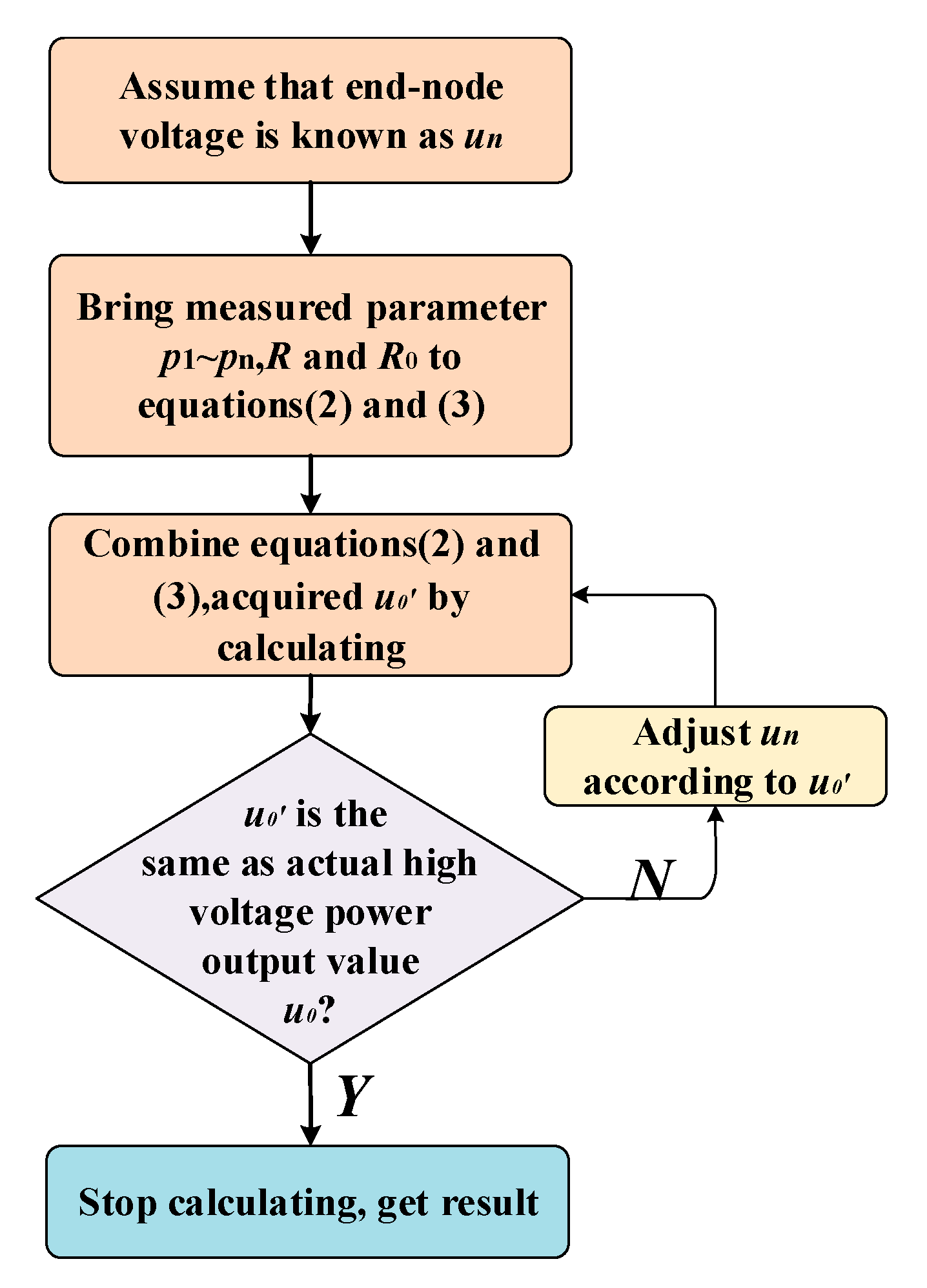
Equations (9) are a typical system of non-linear equations. Traditional algorithms such as the Newton iteration algorithm are used to solve the system of non-linear equations [21,22,23]. However, some problems still exist. The convergence and performance characteristics of the algorithm are highly sensitive to the initial values and the computational efficiency is low [24,25]. By analyzing Equations (2) and (3), we put forward a new algorithm named “reverse algorithm”. The advantage of the reverse algorithm is that highly accurate results can be calculated quickly. Figure 6 illustrates the solution flow chart.
The pseudocode of reverse algorithm is shown in Algorithm 1. We use a reverse algorithm to obtain u1~un and i1~in in Equations (9). Equations (9) are acquired by Equations (2) and (3). The first step is to choose a suitable value of un. In step 2, in is acquired by utilizing the last equation in (3). In step 3 to 6, u1~un−1 and i1~in−1 is calculated by Equations (2) and (3). In step 7, we obtain u0′ and compare it with u0. If the value of u0′ is the same as u0, calculating process is terminated. Otherwise un is adjusted according to u0′ and step 1 to step 7 are repeated till we get the right results.
Algorithm 1. Reverse algorithm ()
Input (n)
Output (u1~un, i1~in)
Known parameters: u0, p1~pn, R, R0
  • do assume un = constant (un needs to adjust according to u0)
  • j = n, ij = pj/uj,
  • for j = n to 2
  • uj−1 = ij*(R + R0) + uj
  • ij−1 = ij + pj−1/uj−1
  • end
  • u0 = 5*i1*R + u1
  • while (u0! = u0)
The reverse algorithm is a specific algorithm for Equations (2) and (3), which is able to reach the same solutions as Equations (9). The Newton iteration algorithm is a common algorithm for nonlinear equations. As shown in Figure 6 and Algorithm 1, the solution procedure of reverse algorithm is simpler than Newton iteration algorithm. When N (N = number of nodes) equals 150, the calculating time of reverse algorithm is about one or two minutes utilizing matlab. The calculating time of Newton iteration is about two or three minutes under the same condition.

4. Simulation and Verification of the Model

We elaborate on the verification of the accuracy of the Newton iteration algorithm and reverse algorithm in Section 4.1. In the laboratory, we perform a test to verify the model. The experimental results verify the accuracy of the model, which is detailed in Section 4.2. In Section 1, it is mentioned that the length of streamer (HQI-Seis) can reach only 7 km with a tracking spacing of 3.125 m. In Section 4.3, we discuss doubts in detail. In further study about the model, we find the reason why MSESS can only support a finite number of nodes under given system parameters.

4.1. Verification of the Accuracy of Two Algorithms

We use the Newton iteration algorithm and reverse algorithm to solve Equations (9) to find the maximum number of nodes that MSESS can operate normally under measured parameters. The results show that the equations have no solution when N increases to 166. The calculating result of the Newton iteration algorithm does not converge, while the reverse algorithm falls into an infinite loop. Neither algorithm produces a result. The calculated result shows that the maximum number of nodes under the current parameters is 165. The voltage of each node is shown in Figure 7. The blue circles represent the result of the Newton iteration algorithm and the red dots stand for the result of the reverse algorithm. The results of the Newton iteration algorithm and the reverse algorithm are nearly the same, which verifies the accuracy of the two algorithms.

4.2. Verification of the Model—Test in Laboratory

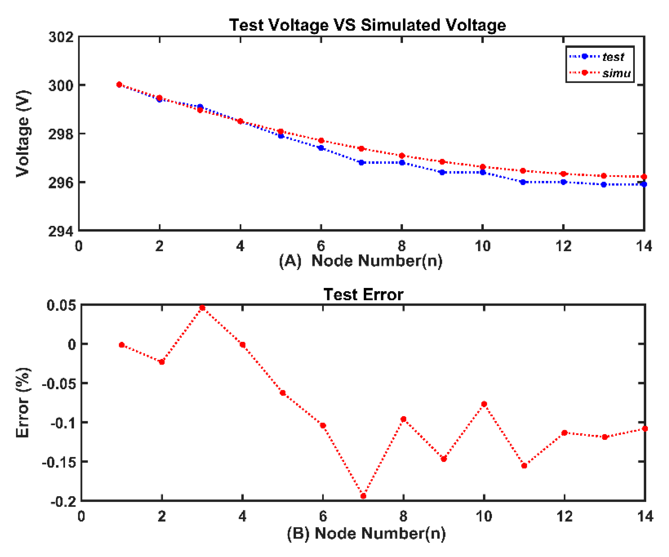
To verify the model under laboratory conditions, we set up a test platform of 1300 m (N = 13). The laboratory’s high-voltage DC power supply is used to simulate the power supply of the geophysical survey vessel and the electronic load is used to simulate DAS. The resistance of the power cable (100 m) was about 2.06 Ω.
Figure 8 illustrates the comparison of test results and simulated results. The maximum error of voltage was less than 0.2%. This error comes from the inaccuracy of the electronic load. Considering the minor error and the source of the error, the experiment proves that the model is accurate.

4.3. Reason for the Existence of Maximum Number of Nodes

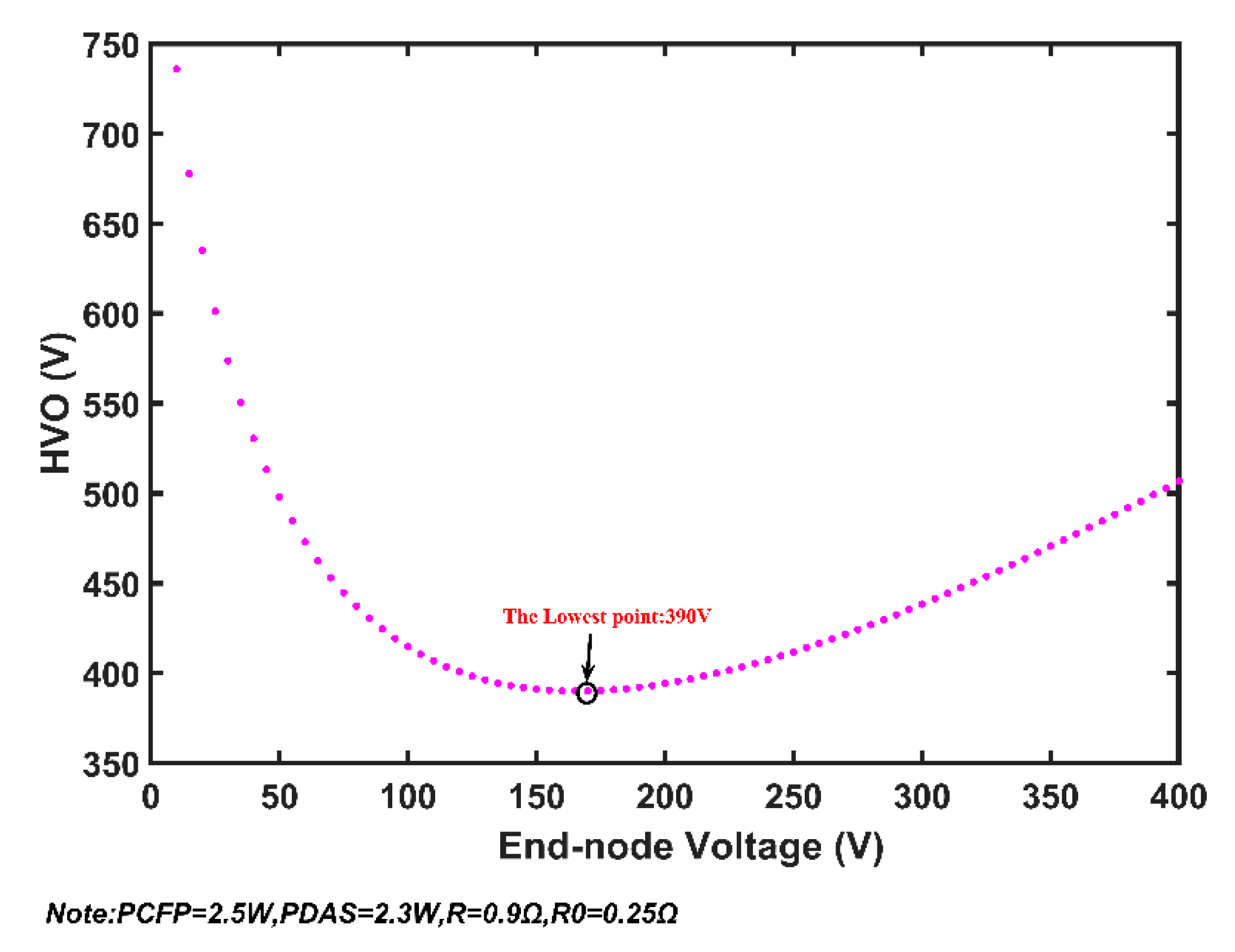
Assuming that the model and algorithms are accurate, the results of the two algorithms indicate that MSESS can operate normally at the measured parameters only when the number of nodes is less than or equals 165. If one more node is added, the equations will have no solution and the system will misbehave. There should be some reason for this phenomenon. We undertook further research to determine a reasonable explanation. The relationship between HVO (u0 in Figure 4) and end-node voltage (un in Figure 4) is presented in Figure 9 when N equals 165. The figure illustrates the following problem: if HVO exceeds the value of the lowest point (390 V), there will be two end-node voltage values, which is inconsistent with the actual situation. When the system is stable, the end-node voltage should be a unique value. Using one node (N = 1) as an example, we conduct analyses using the simplified system structure illustrated in Figure 10.
The equations for finding the values of u1 and i is shown as simultaneous Equations (10):
{ u 0 = u 1 + i ( R + R 0 ) p = u 1 i
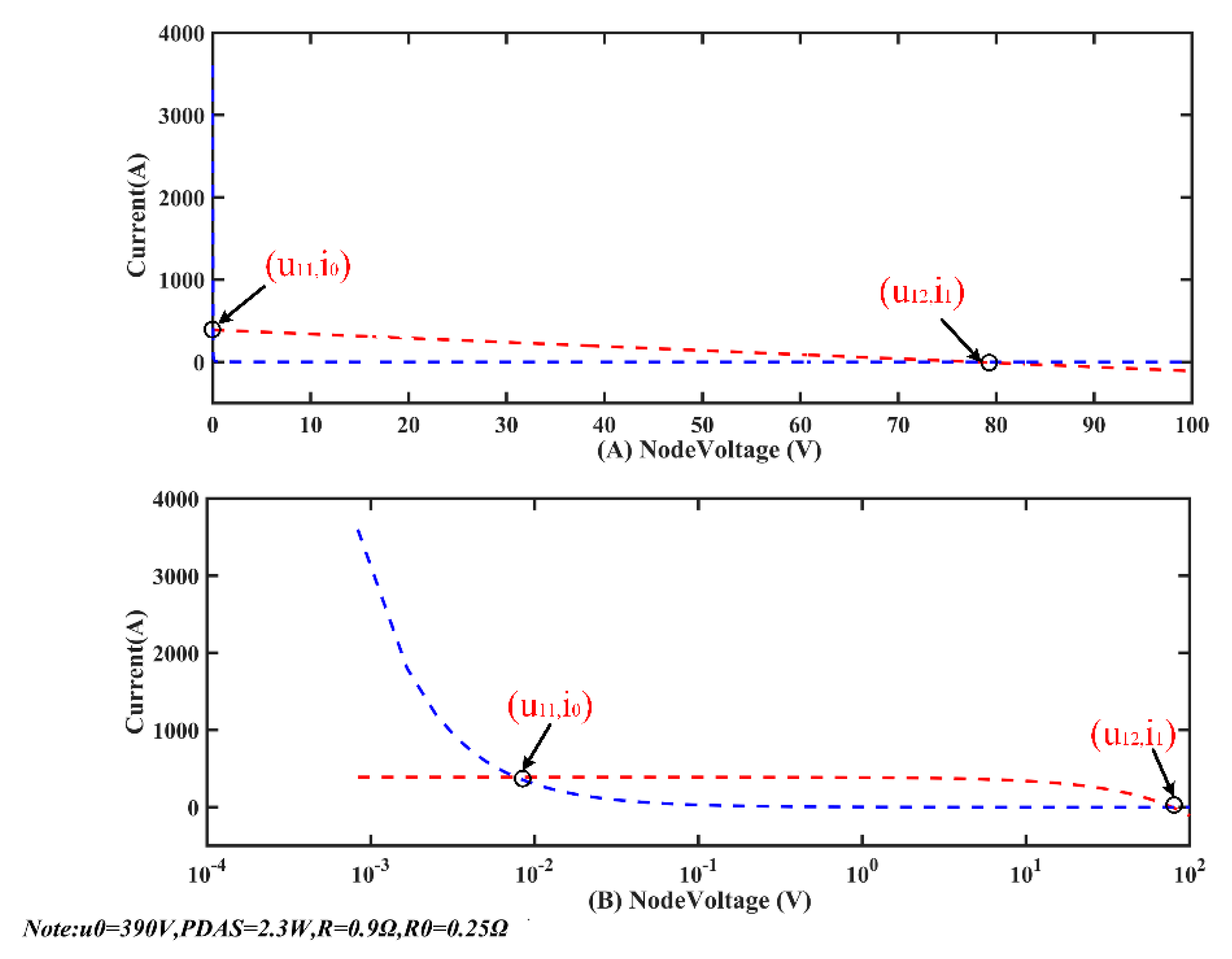
The system parameters are u0 = 390 V, R = 0.9 Ω, R0 = 0.25 Ω, and p = 2.3/eff (1). The result of the calculations, in both a linear coordinate system (on the top) and a logarithmic coordinate system (at the bottom) is shown in Figure 11. The red curve represents the relationship between u1 and i shown in the first equation of (10), and the blue curve represents the relationship between u1 and i in the second equation in (10). The intersection of the two curves are the solutions of Equations (10). From the curve on the logarithmic coordinate axes, it can be seen clearly that the equations have two mathematical solutions: (u11, i0) and (u12, i1). The solution (u11, i0) expresses as u11 is small (10−2), while i0 is very large (102). The characteristics of (u12, i1) are opposite. (u11, i0) and (u12, i1) are named as math solution. When MSESS runs, there is only one solution corresponding to the actual situation. The current cannot be hundreds of ampere in a functioning system. Therefore, (u12, i1) corresponds to the actual parameter when the system is running. (u12, i1) is named as the physical solution.
Our analysis of the special case (N = 1) indicates the existence of mathematical solution and physical solution. When N increases to 165, the relationship of the end-node voltage and HVO is shown in Figure 12. In the left part, once HVO exceeds the lowest point, the end-node voltage will have two numerical values. The two solutions correspond to the mathematical solution. The right part corresponds to the physical solution, which is meaningful for actual situation. The lowest point of the curve represents the minimum value of HVO at which MSESS will operate normally at 165 nodes.
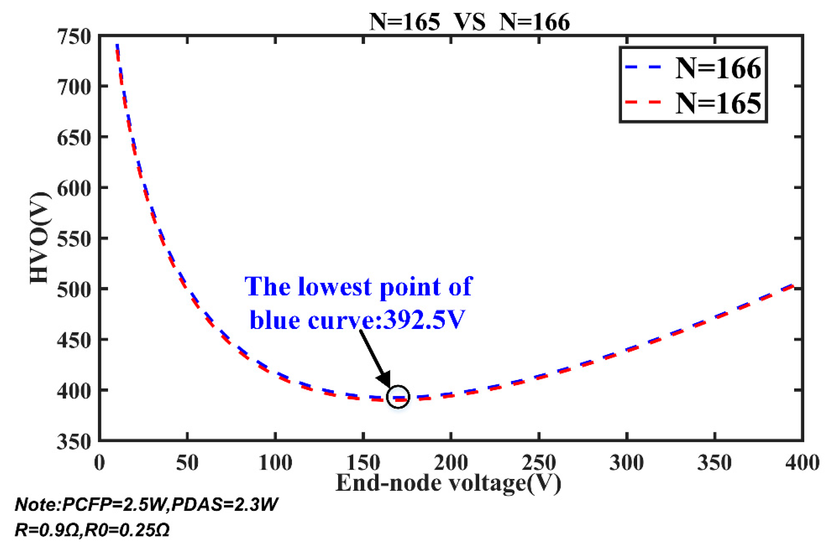
Further verification is illustrated in Figure 13. The blue curve shows the relationship of HVO and the end-node voltage when N equals 166. The lowest point of blue curve is 392.5, which is the minimum value of HVO to make MSESS work normally. Once the value of HVO is less than 392.5 V, MSESS is unable to function when N equals 166. The red curve represents the relationship between HVO and end-node voltage when N equals 165. The lowest point of red curve is 390. It is obvious that HVO must be at least 392.5 V to make MSESS operate normally at 166 nodes, and there is no solution for the equations if HVO is 390 V. If HVO is set to 390 V and N equals 166, what will happen in actual situation?
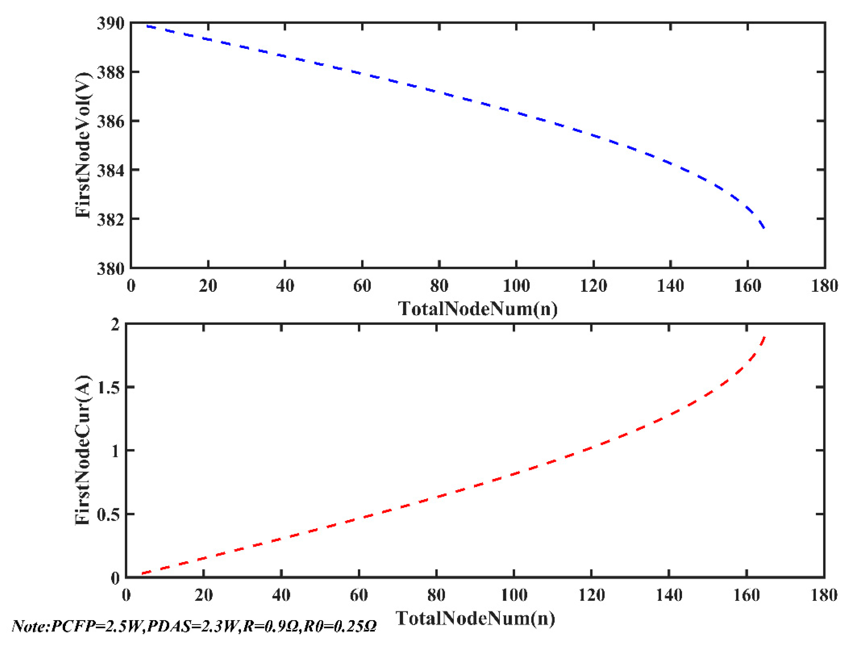
Figure 14 shows the varying curve of the first-node current (i1 in Figure 4) and voltage (u1 in Figure 4) as the total number of nodes (here it stands for N, the maximum value equals 165) increases. When system parameters (u0, R, R0, PCFP, PDAS) are constant, the first-node current increases sharply and the first-node voltage drops sharply as the total number of nodes increases to 165. From the trend of the curve, the current of the first node is an infinite value when N equals 166. Therefore in an actual situation, if HVO is set to 390 V and N equals 166, the output current of the power supply will be an infinite value. The power supply will turn on the overcurrent protection and disconnect the output.
From the analysis above, it can be concluded that for given system parameters and a certain number of nodes, HVO must have a minimum value to make the system work properly. From another perspective, once the system parameters and HVO are specified, the number of nodes with which the system works properly is determined. When the number of nodes exceeds the maximum value, the system current will be an infinite value and the power supply will shut down due to the function of overcurrent protection. This is why the number of nodes supported by “HQI-Seis” is limited.

5. Discussion of the Model

According to the model, the line loss on the power cable and the power consumption of each node (p1~pn in Figure 4) affect the length of MSESS. We have a detailed analysis in Section 5.1. To calculate the maximum length of MSESS under given system parameters quickly, we develop a kind of software. In Section 5.2, the function of the software is introduced.

5.1. Factors Affecting the Length of the Streamer

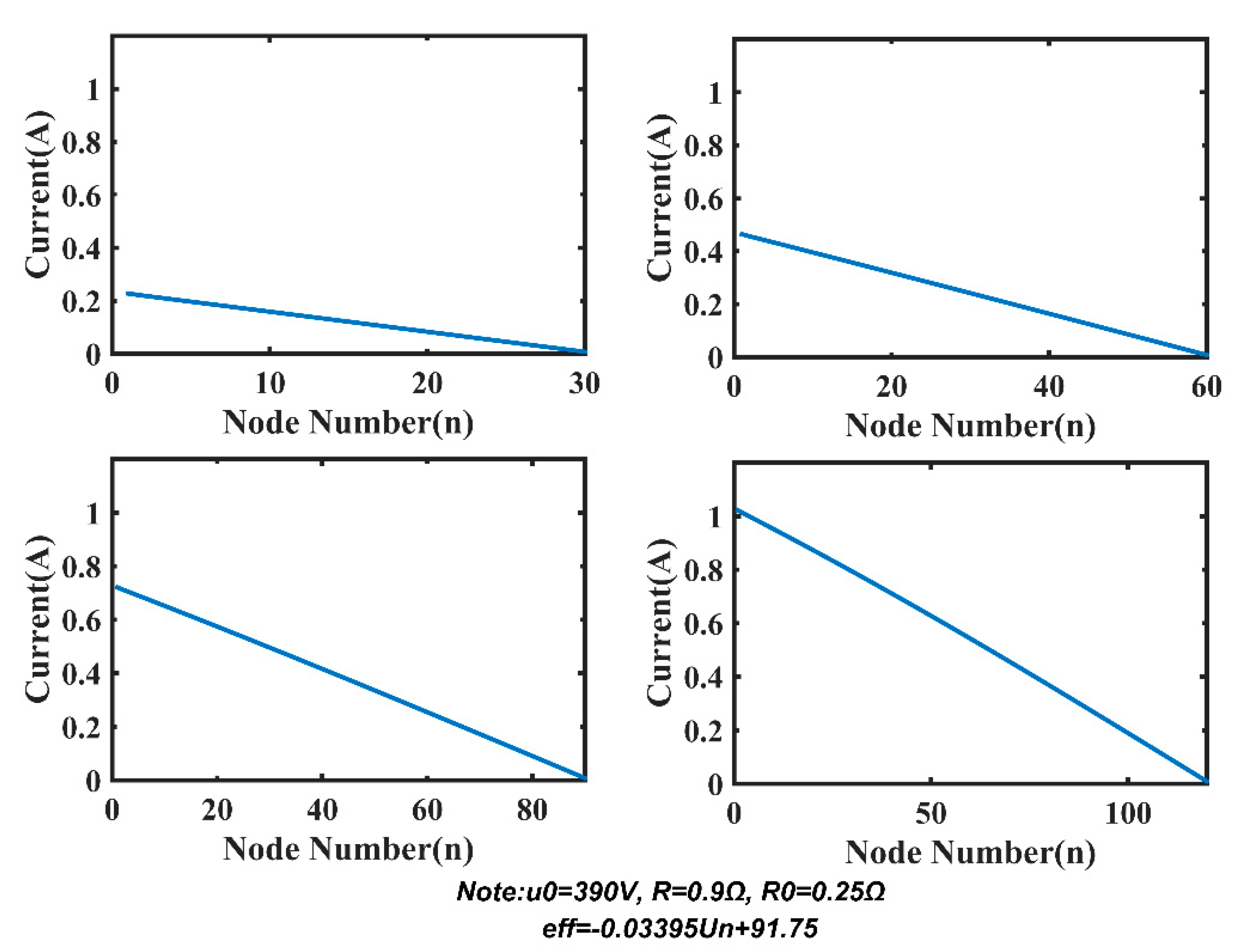
Based on the optimized model, we research two factors affecting the length and power consumption of MSESS, including R and PDAS. Figure 15 demonstrates voltage distribution with 30, 60, 90, and 120 nodes under the condition that system parameters are u0 = 390 V, R = 0.9 Ω, R0 = 0.25 Ω, and PDAS = 2.3 W. We can see that the voltage on the power line remains relatively stable when there are only 30 or 60 nodes. When the number of nodes increases to 90 or 120, the voltage drops rapidly due to line loss on the power line. Corresponding to Figure 15, the current distribution is shown in Figure 16. As the number of nodes increases, the total current increases accordingly, which results in a rise in system power consumption.
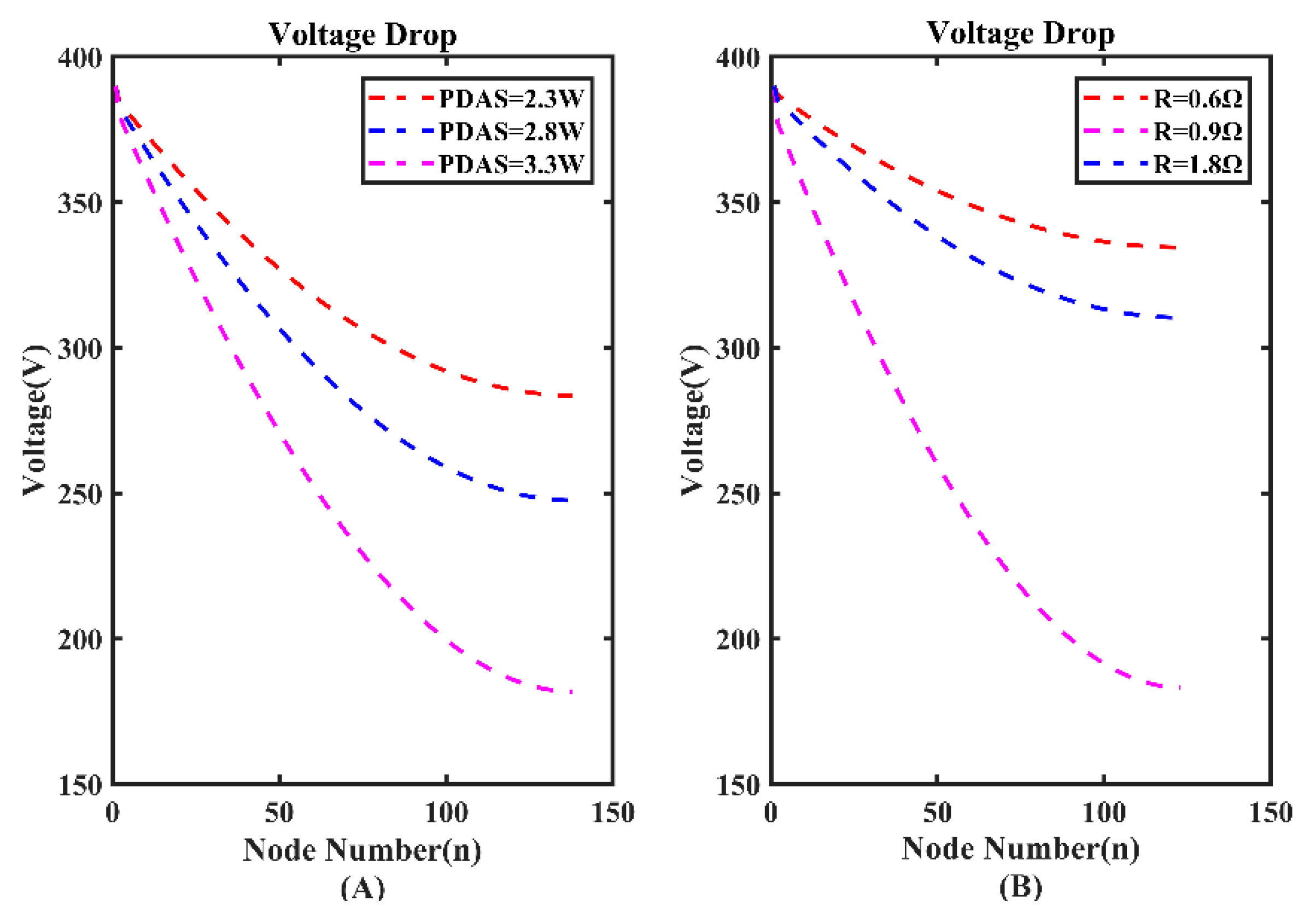
The value of power consumption of each node (p1~pn in Figure 4) affects the length of MSESS. Figure 17A illustrates the curve of voltage drop with 137 nodes. It is obvious that voltage descends rapidly when PDAS increases from 2.3 W to 3.3 W. For further research, we calculate the maximum number of nodes using a range of PDAS (Table 1). As PDAS changes from 3.3 W to 2.3 W, the maximum number of nodes increases from 137 to 165. Therefore, reducing the power of a single node is an effective way to raise the number of nodes supported by MSESS.
Another important factor affecting the length of MSESS is the value of R, which is the key to line loss. In the laboratory, the power supply line is composed of two 14 AWG (American wire gauge) lines (R = 0.9 Ω). We run a simulation under the condition that R is 0.6 Ω (the value of R of three 14 AWG lines) and 1.8 Ω (the value of R of one 14 AWG line). The results of the simulation are shown in Figure 17B. When the value of R increases, the voltage drops rapidly. The maximum number of nodes with different value of R is shown in Table 2.
Reducing the value of R is an effective approach to increase the length of MSESS. Due to the harsh working environment of marine seismic exploration, it is impossible to reduce the impedance by using multi-strand power lines in parallel in engineering applications. This shows reducing the value of PDAS is a more effective way to design long MSESS.

5.2. Predicting the Maximum Length of MSESS

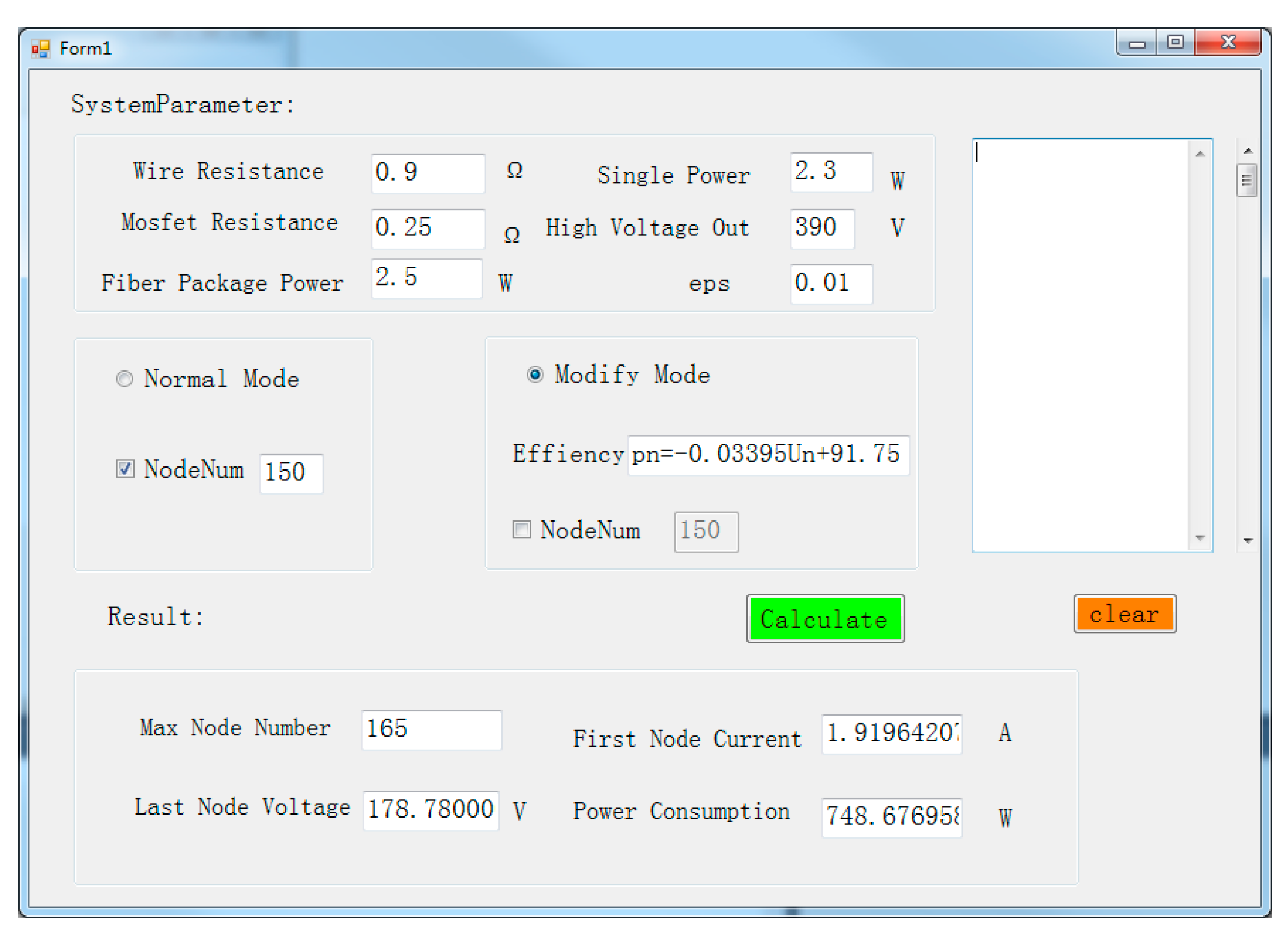
The length of the MSESS affects the depth of the exploration target layer, which is critical in designing the system. In order to quickly acquire the maximum length that can be supported by MSESS under certain parameters, we use C# to develop a human-computer interaction interface program based on the reverse algorithm. The graphical interface is shown in Figure 18. There are two main functions of the software. One function is to find the maximum number of nodes supported by MSESS under given system parameters. The other is to obtain other parameters of the system (end-node voltage, system power consumption, etc.) given known number of nodes. When system parameters (such as supply voltage, single node power consumption, wire resistance, etc.) are given, the maximum number of nodes can be calculated quickly to predict the maximum length supported by MSESS.

6. Conclusions

This paper researches the power system used in marine seismic exploration. A model to analyze the voltage distribution and current distribution is built. Non-linear equations are established for the model, which are solved by the Newton iteration algorithm and reverse algorithm. A test platform of 1300 m is built in the laboratory and the accuracy of the model is verified based on the analysis of measured results and simulated results. With further research, we discover why “HQI-Seis” can reach only 7 km under given system parameters. We have a detailed discussion about the two factors (the value of R and PDAS) affecting the length and power consumption of MSESS. By research, reducing the value of PDAS is a more effective way to design long MSESS. Based on the reverse algorithm, we develop a kind of software that is able to quickly calculate the maximum number of nodes that the system can support. System designers can predict the maximum length of MSESS conveniently using the software. The research results of this paper are of great significance to design long MSESS. The research methods in this paper could also be applied to relevant works such as large-scale sensor networks in land seismic exploration.

Author Contributions

Conceptualization, H.Y. and K.S.; Methodology, J.Y.; Software, H.Y.; Investigation, K.Z.; Data curation, W.L. and C.W.; Writing, H.Y. All authors have read and agreed to the published version of the manuscript.

Funding

This research was funded by National Key R&D Program of China under Grant No. 2016YFC0303200 and National Natural Science Foundation of China under Grant No. 41674179.

Conflicts of Interest

The authors declare no conflict of interest.

References

  1. Hu, W.R.; Bao, J.W.; Hu, B. Trend and progress in global oil and gas exploration. Pet. Explor. Dev. 2013, 40, 439–443. [Google Scholar] [CrossRef]
  2. Sun, L.D.; Fang, C.L.; Sa, L.M.; Yang, P.; Sun, Z.D. Innovation and prospect of geophysical technology in the exploration of deep oil and gas. Pet. Explor. Dev. 2015, 42, 454–465. [Google Scholar] [CrossRef]
  3. Xin, S. Analysis of deep oil and gas reservoirs exploration prospect. China Pet. Explor. 2005, 1, 1–10. [Google Scholar]
  4. Lin, H.M.; Shi, H.S. Hydrocarbon accumulation conditions and exploration direction of Baiyun–Liwan deep water areas in the Pearl River Mouth Basin. Nat. Gas Ind. B 2014, 1, 150–158. [Google Scholar] [CrossRef] [Green Version]
  5. Wang, Y.R.; Miao, X.H.; Jiang, H.; Chen, M.; Liu, Y.; Xu, W.S.; Meng, D. Review on underwater sound absorption materials and mechanisms. Adv. Mech. 2017, 47, 92–121. [Google Scholar]
  6. Xu, C.C.; Zou, W.H.; Yang, Y.M.; Duan, Y.; Shen, Y.; Luo, B. Status and prospects of deep oil and gas resources exploration and development onshore China. J. Nat. Gas Geosci. 2018, 3, 11–24. [Google Scholar] [CrossRef]
  7. Jia, C.Z. Breakthrough and significance of unconventional oil and gas to classical petroleum geology theory. Pet. Explor. Dev. 2017, 44, 1–10. [Google Scholar] [CrossRef]
  8. Wang, X.C.; Li, X.L.; Zhang, H.B.; Hao, X.Z.; Yu, K.B. Optical fiber marine seismic exploration system feasibility study. Acta Geophys. 2019, 67, 1403–1411. [Google Scholar] [CrossRef]
  9. Grindheim, J.V.; Revhaug, I.; Pedersen, E.; Solheim, P. Comparison of Two Models for Prediction of Seismic Streamer State Using the Ensemble Kalman Filter. J. Offshore Mech. Arct. Eng. 2018, 140. [Google Scholar] [CrossRef]
  10. Grindheim, J.V.; Revhaug, I.; Pedersen, E.; Solheim, P. Position Prediction of Marine Seismic Streamer Cables Using Various Kalman Filter Methods. J. Offshore Mech. Arct. Eng. 2019, 141, 051701. [Google Scholar] [CrossRef] [Green Version]
  11. Kong, F.D.; He, T.; Spence, G.D. Application of deep-towed multichannel seismic system for gas hydrate on mid-slope of northern Cascadia margin. Sci. China Earth Sci. 2012, 55, 758–769. [Google Scholar] [CrossRef]
  12. Luo, D.; Cai, F.; Wu, Z.Q.; Yan, G.J.; Du, R.L. The key technologies of marine small scale high resolution multichannel seismic high-precision imaging. Chin. J. Geophys. 2019, 62, 730–742. [Google Scholar]
  13. Li, Z.; Mei, H.W.; Wang, L.M. A Power Supply Technology for a Low-Power Online Monitoring Sensor Based on Electric Field Induction. Sensors 2019, 19, 2169. [Google Scholar] [CrossRef] [PubMed] [Green Version]
  14. Manuel, A.; Roset, X.; Del Rio, J.; Toma, D.M.; Carreras, N.; Panahi, S.S.; Garcia-Benadi, A.; Owen, T.; Cadena, J. Ocean Bottom Seismometer: Design and Test of a Measurement System for Marine Seismology. Sensors 2012, 12, 3693–3719. [Google Scholar] [CrossRef] [PubMed] [Green Version]
  15. Howe, B.M.; Kirkham, H.; Vorperian, V. Power system considerations for undersea observatories. IEEE J. Ocean. Eng. 2002, 27, 267–274. [Google Scholar] [CrossRef]
  16. Vedachalam, N.; Babu, S.M.; Ramadass, G.A.; Atmanand, M.A. Review of maturing multi-megawatt power electronic converter technologies and reliability modeling in the light of subsea applications. Appl. Ocean Res. 2014, 46, 28–39. [Google Scholar] [CrossRef]
  17. Narayanaswamy, V. Review of challenges in reliable electric power delivery to remote deep water enhanced oil recovery systems. Appl. Ocean Res. 2013, 43, 53–67. [Google Scholar] [CrossRef]
  18. Cao, P.; Song, K.Z.; Yang, J.F.; Ruan, F.M. Design of a large remote seismic exploration data acquisition system, with the architecture of a distributed storage area network. J. Geophys. Eng. 2011, 8, 27–34. [Google Scholar] [CrossRef]
  19. Song, K.Z.; Cao, P.; Yang, J.F.; Ruan, F.M. A high-speed transmission method for large-scale marine seismic prospecting systems. J. Geophys. Eng. 2012, 9, 737–748. [Google Scholar]
  20. Ruan, F.M.; Yang, K.; Wu, Q.Y.; Zhu, Y.Q.; Li, L. Application of Slant Streamer Marine Seismic Survey in the South China Sea. In Proceedings of the 2014 SEG Annual Meeting, Denver, CO, USA, 26–31 October 2014. [Google Scholar]
  21. Chun, C. A new iterative method for solving nonlinear equations. Appl. Math. Comput. 2006, 178, 415–422. [Google Scholar] [CrossRef]
  22. Thukral, R. A new eighth-order iterative method for solving nonlinear equations. Appl. Math. Comput. 2010, 217, 222–229. [Google Scholar] [CrossRef]
  23. Bi, W.H.; Wu, Q.B.; Ren, H.M. A new family of eighth-order iterative methods for solving nonlinear equations. Appl. Math. Comput. 2009, 214, 236–245. [Google Scholar] [CrossRef]
  24. Sharma, J.R. A note on the convergence order of some recent methods for solving nonlinear equations. Appl. Math. Comput. 2016, 273, 793–796. [Google Scholar] [CrossRef]
  25. Traub, J.F.; Wozniakowski, H. Convergence and Complexity of Newton Iteration for Operator Equations. J. ACM 1979, 26, 250–258. [Google Scholar] [CrossRef]
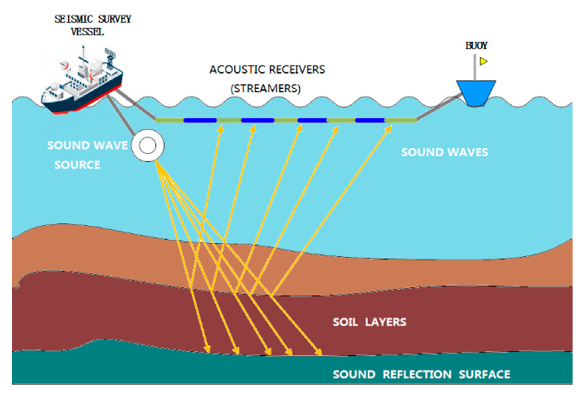
Figure 1. Working process of marine seismic exploration.
Sensors 20 00028 g001
Figure 2. Internal power supply structure of streamer.
Sensors 20 00028 g002
Figure 3. Architecture of the power system.
Sensors 20 00028 g003
Figure 4. Equivalent model of power system.
Sensors 20 00028 g004
Figure 5. Simplified model of power system.
Sensors 20 00028 g005
Figure 6. Calculation process of the reverse algorithm.
Sensors 20 00028 g006
Figure 7. Calculation results of Newton iteration and reverse algorithms.
Sensors 20 00028 g007
Figure 8. Test result: (A) comparison of simulated voltage and test voltage (B) error percentage of voltage.
Sensors 20 00028 g008
Figure 9. Relationship of high-voltage direct current output (HVO) and end-node voltage.
Sensors 20 00028 g009
Figure 10. Simplified model of one node.
Sensors 20 00028 g010
Figure 11. Solution result of one node.
Sensors 20 00028 g011
Figure 12. Comparison of the mathematical solution and physical solution.
Sensors 20 00028 g012
Figure 13. Relationship of HVO and end-node voltage as N = 165 and N = 166.
Sensors 20 00028 g013
Figure 14. First-node voltage and current vary as the total number of nodes increases.
Sensors 20 00028 g014
Figure 15. Voltage distribution.
Sensors 20 00028 g015
Figure 16. Current distribution.
Sensors 20 00028 g016
Figure 17. (A) Voltage drop with different power consumption of data acquisition station (PDAS). (B) Voltage drop with different R.
Sensors 20 00028 g017
Figure 18. Software interface.
Sensors 20 00028 g018
Table 1. Maximum number of nodes under different PDAS.
PDAS (W)HVO (V)End-Node Voltage (V)p0 (W)Maximum Number of Nodes
2.3390178.77748.677165
2.8390181.99814.9769149
3.3390181.79883.6328137
Table 2. Maximum number of nodes with different R.
R (Ω)HVO (V)End-Node Voltage (V)p0 (W)Maximum Number of Nodes
0.6390176.97879.04193
0.9390178.77748.677165
1.8390183.18548.28122