HD/FD and DF/AF with Fixed-Gain or Variable-Gain Protocol Switching Mechanism over Cooperative NOMA for Green-Wireless Networks


Abstract
1. Introduction
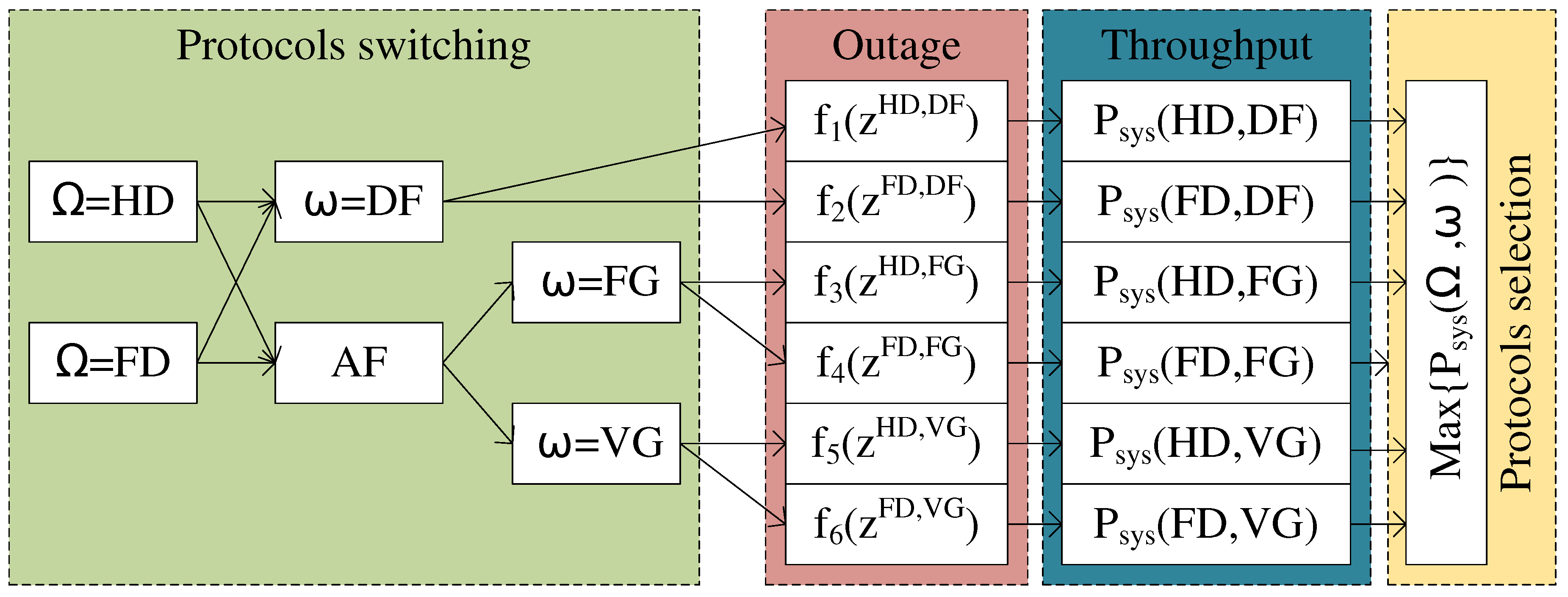
- An investigation into the system performance of cooperative NOMA under six scenarios: (1) HD and DF relay; (2) FD and DF relay; (3) HD and AF with FG relay; (4) FD and AF with FG relay; (5) HD and AF with VG relay; (6) FD and AF with VG relay. The outage probability of each scenario is presented in a closed form.
- A proposal of a mechanism for switching protocols and optimizing system performance by selecting the best protocol to forward a signal to the next user.
- An investigation into the system performance on different signal-to-noise-ratios (SNRs) to find a suitable means of transmitting power to avoid wasting energy. Energy saving is required in G-WNs.
- The results coming from the analysis and simulation of outage probability, system throughput and EE are performed by Matlab (This paper used Matlab software version R2017b, made by The MathWorks, Inc., 3 Apple Hill Drive Natick, MA 01760 USA 508-647-7000) software. In addition, an algorithm used for Monte Carlo simulation is also proposed for investigating the outage probability of individual scenarios. The simulation results are used for verifying the analysis results. The figures are presented clearly and accurately in order to demonstrate our propositions.
2. Experimental Models
2.1. First Time Slot (FTS)
2.2. Second Time Slot (STS)
2.2.1. DF Protocols at the Relay
2.2.2. AF with FG/VG Protocols at the Relay
3. System Performance Analysis
3.1. Outage Probability
- Case 1: The instantaneous bit rate cannot reach to the bit rate threshold , in other words .
- Case 2: The instantaneous bit rate can reach to the bit rate threshold but the instantaneous bit rate cannot reach to the bit rate threshold , in other words , and .
- Case 1: The instantaneous bit rate cannot reach the bit rate threshold , in other words .
- Case 2: The instantaneous bit rate can reach to the bit rate threshold but the instantaneous bit rate cannot reach to the bit rate threshold , in other words, , and .
3.1.1. HD and DF Protocols at the Relay ()
3.1.2. FD and DF Protocols at the Relay ()
3.1.3. HD and AF with FG Protocols at the Relay ()
3.1.4. FD and AF with FG Protocols at the Relay ()
3.1.5. HD and AF with VG Protocols at the Relay ()
3.1.6. FD and AF with VG Protocols at the Relay ()
3.2. System Throughput
3.3. Energy Efficiency
3.4. Protocol Switching Mechanism
4. Numerical Results and Discussion

4.1. Numerical Results and Discussion for Outage Probability
4.2. Numerical Results and Discussion for System Throughput
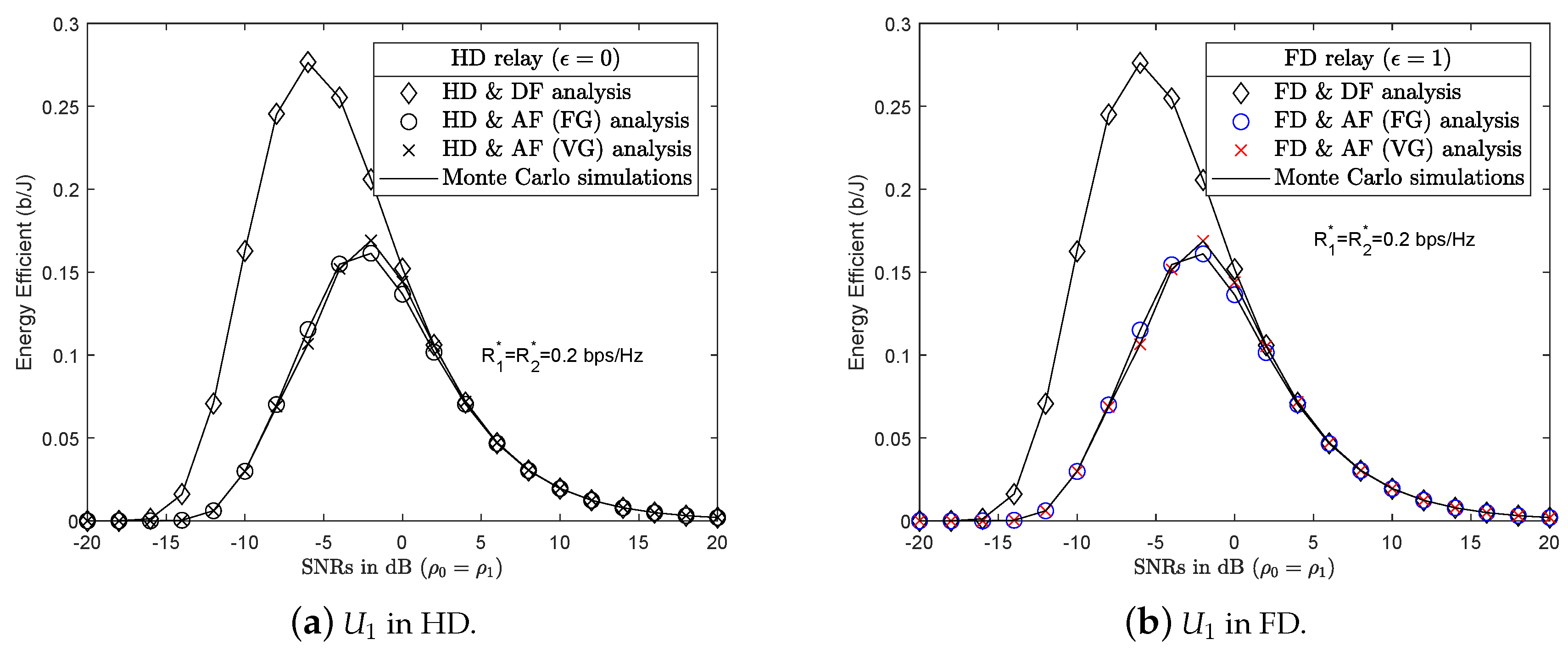
4.3. Numerical Results and Discussion for Energy Efficiency
4.4. Protocol Switching Mechanism
4.4.1. PSS Based on Outage Probability
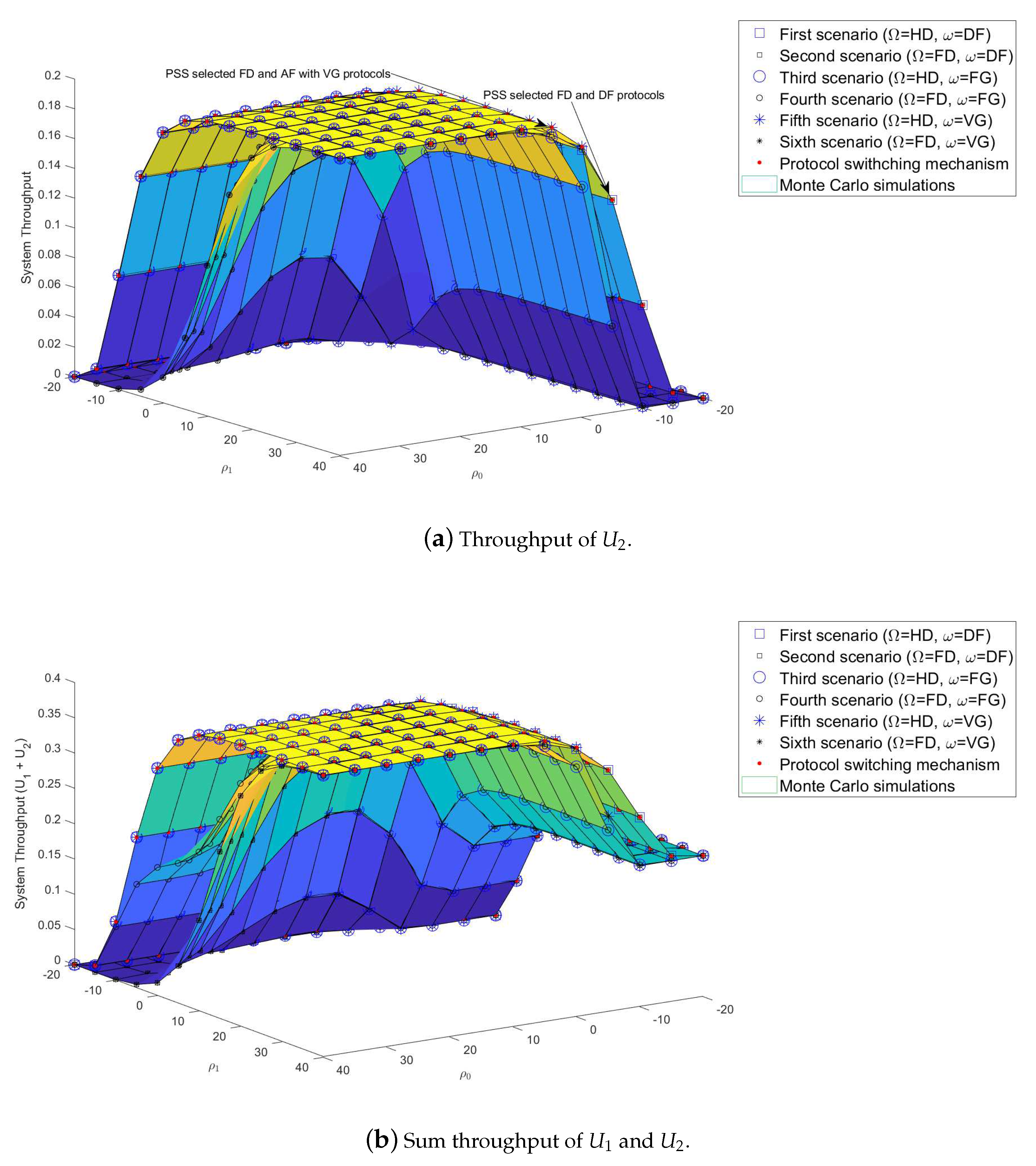
4.4.2. PSS Based on Throughput
4.4.3. PSS Based on EE
5. Conclusions
Author Contributions
Funding
Acknowledgments
Conflicts of Interest
Abbreviations
| No. | Abbreviations | Full Description |
| 1 | AF | Amplify-and-forward |
| 2 | AWGNs | Additive white Gaussian noises |
| 3 | BS | Base station |
| 4 | CDF | Cumulative distribution function |
| 5 | CSI | Channel state information |
| 6 | DF | Decode-and-forward |
| 7 | EE | Energy efficient |
| 8 | FD | Full-duplex |
| 9 | Fig. | Figure |
| 10 | FG | Fixed gain |
| 11 | G-WNs | Green-wireless networks |
| 12 | HD | Half-duplex |
| 13 | NOMA | Non-orthogonal multiple access |
| 14 | Probability density function | |
| 15 | PSM | Protocol switching mechanism |
| 16 | PSS | Protocol switching selection |
| 17 | QoS | Quality of service |
| 18 | S | Source |
| 19 | SIC | Successive interference cancellation |
| 20 | SINR | Signal-to-interference-plus-noise ratio |
| 21 | SNR | Signal-to-noise ratio |
| 22 | The i-th user | |
| 23 | VG | Variable gain |
Appendix A
References
- Li, Q.C.; Niu, H.; Papathanassiou, A.T.; Wu, G. 5G network capacity: Key elements and technologies. IEEE Veh. Technol. Mag. 2014, 9, 71–78. [Google Scholar] [CrossRef]
- Saito, Y.; Benjebbour, A.; Kishiyama, Y.; Nakamura, T. System level performance evaluation of downlink non-orthogonal multiple access (NOMA). In Proceedings of the 2013 IEEE 24th Annual International Symposium on Personal, Indoor, and Mobile Radio Communications (PIMRC), London, UK, 8–11 September 2013; pp. 611–615. [Google Scholar]
- Ding, Z.; Yang, Z.; Fan, P.; Poor, H. On the Performance of Non-Orthogonal Multiple Access in 5G Systems with Randomly Deployed Users. IEEE Signal Process. Lett. 2014, 21, 1501–1505. [Google Scholar] [CrossRef]
- Higuchi, K.; Benjebbour, A. Non-orthogonal Multiple Access (NOMA) with Successive Interference Cancellation for Future Radio Access. IEICE Trans. Commun. 2015, 98, 403–414. [Google Scholar] [CrossRef]
- Dai, L.; Wang, B.; Ding, Z.; Wang, Z.; Chen, S.; Hanzo, L. A Survey of Non-Orthogonal Multiple Access for 5G. IEEE Commun. Surv. Tutor. 2018, 20, 2294–2323. [Google Scholar] [CrossRef]
- Islam, S.; Zeng, M.; Dobre, O.; Kwak, K. Resource Allocation for Downlink NOMA Systems: Key Techniques and Open Issues. IEEE Wirel. Commun. 2018, 25, 40–47. [Google Scholar] [CrossRef]
- Lei, L.; Yuan, D.; Ho, C.; Sun, S. Power and Channel Allocation for Non-Orthogonal Multiple Access in 5G Systems: Tractability and Computation. IEEE Trans. Wirel. Commun. 2016, 15, 8580–8594. [Google Scholar] [CrossRef]
- Wan, D.; Wen, M.; Ji, F.; Liu, Y.; Huang, Y. Cooperative NOMA Systems With Partial Channel State 527 Information Over Nakagami-m Fading Channels. IEEE Trans. Commun. 2018, 66, 947–958. [Google Scholar] [CrossRef]
- Timotheou, S.; Krikidis, I. Fairness for Non-Orthogonal Multiple Access in 5G Systems. IEEE Signal Process. Lett. 2015, 22, 1647–1651. [Google Scholar] [CrossRef]
- Men, J.; Ge, J.; Zhang, C. Performance Analysis for Downlink Relaying Aided Non-Orthogonal Multiple Access Networks with Imperfect CSI Over Nakagami-m Fading. IEEE Access 2017, 5, 998–1004. [Google Scholar] [CrossRef]
- Ding, Z.; Peng, M.; Poor, H.V. Cooperative non-orthogonal multiple access in 5G systems. IEEE Commun. Lett. 2015, 19, 1462–1465. [Google Scholar] [CrossRef]
- Choi, J. Non-orthogonal multiple access in downlink coordinated two point systems. IEEE Commun. Lett. 2014, 18, 313–316. [Google Scholar] [CrossRef]
- Liu, Y.; Ding, Z.; Elkashlan, M.; Poor, H.V. Cooperative nonorthogonal multiple access with simultaneous wireless information and power transfer. IEEE J. Sel. Areas Commun. 2016, 34, 938–953. [Google Scholar] [CrossRef]
- Kim, J.-B.; Lee, I.-H. Non-orthogonal multiple access in coordinated direct and relay transmission. IEEE Commun. Lett. 2015, 19, 2037–2040. [Google Scholar] [CrossRef]
- Choi, J. On the spectral efficient nonorthogonal multiple access schemes. In Proceedings of the 2016 European Conference on Networks and Communications (EuCNC), Athens, Greece, 27–30 June 2016; pp. 277–281. [Google Scholar]
- Laneman, J.N.; Tse, D.N.C.; Wornell, G.W. Cooperative diversity in wireless networks: Efficient protocols and outage behavior. IEEE Trans. Inf. Theory 2004, 50, 3062–3080. [Google Scholar] [CrossRef]
- Zhang, Z.; Ma, Z.; Xiao, M.; Ding, Z.; Fan, P. Full-duplex device-to-device aided cooperative non-orthogonal multiple access. IEEE Trans. Veh. Technol. 2019; to be published. [Google Scholar]
- Ju, H.; Oh, E.; Hong, D. Improving efficiency of resource usage in two-hop full duplex relay systems based on resource sharing and interference cancellation. IEEE Trans. Wireless Commun. 2009, 8, 3933–3938. [Google Scholar]
- Wang, Q.; Dong, Y.; Xu, X.; Tao, X. Outage probability of full-duplex AF relaying with processing delay and residual self-interference. IEEE Commun. Lett. 2015, 19, 783–786. [Google Scholar] [CrossRef]
- Zhang, Z.; Chai, X.; Long, K.; Vasilakos, A.V.; Hanzo, L. Full-duplex techniques for 5G networks: Self-interference cancellation, protocol design, and relay selection. IEEE Commun. Mag. 2015, 53, 128–137. [Google Scholar] [CrossRef]
- Osorio, D.P.M.; Olivo, E.E.B.; Alves, H.; Filho, J.C.S.S.; Latva-aho, M. Exploiting the direct link in full-duplex amplify-and-forward relaying networks. IEEE Signal Process. Lett. 2015, 22, 1766–1770. [Google Scholar] [CrossRef]
- Kwon, T.; Lim, S.; Choi, S.; Hong, D. Optimal duplex mode for DF relay in terms of the outage probability. IEEE Trans. Veh. Technol. 2010, 59, 3628–3634. [Google Scholar] [CrossRef]
- Tran, T.; Do, D.; Voznak, M. On Outage Probability and Throughput Performance of Cognitive Radio Inspired NOMA Relay System. Adv. Electr. Electron. Eng. 2018, 16. [Google Scholar] [CrossRef]
- Riihonen, T.; Werner, S.; Wichman, R. Hybrid full-duplex/half-duplex relaying with transmit power adaptation. IEEE Trans. Wireless Commun. 2011, 10, 3074–3085. [Google Scholar] [CrossRef]
- Yue, X.; Liu, Y.; Kang, S.; Nallanathan, A.; Ding, Z. Exploiting Full/Half-Duplex User Relaying in NOMA Systems. IEEE Trans. Commun. 2018, 66, 560–575. [Google Scholar] [CrossRef]
- Yue, X.; Liu, Y.; Kang, S.; Nallanathan, A. Performance Analysis of NOMA With Fixed Gain Relaying Over Nakagami-m Fading Channels. IEEE Access 2017, 5, 5445–5454. [Google Scholar] [CrossRef]
- Ding, Z.; Dai, H.; Poor, H. Relay Selection for Cooperative NOMA. IEEE Wirel. Commun. Lett. 2016, 5, 416–419. [Google Scholar] [CrossRef]
- Lu, X.; Wang, P.; Niyato, D.; Kim, D.I.; Han, Z. Wireless networks with RF energy harvesting: A contemporary survey. IEEE Commun. Surv. Tutor. 2015, 17, 757–789. [Google Scholar] [CrossRef]
- Perera, T.P.; Jayakody, D.; Sharma, S.; Chatzinotas, S.; Li, J. Simultaneous Wireless Information and Power Transfer (SWIPT): Recent Advances and Future Challenges. IEEE Commun. Surv. Tutor. 2018, 20, 264–302. [Google Scholar] [CrossRef]
- Tam, H.H.M.; Tuan, H.D.; Nasir, A.A.; Duong, T.Q.; Poor, H.V. MIMO energy harvesting in full-duplex multi-user networks. IEEE Trans. Wirel. Commun. 2017, 16, 3282–3297. [Google Scholar] [CrossRef]
- Tran, T.; Voznak, M. Multi-Points Cooperative Relay in NOMA System with N-1 DF Relaying Nodes in HD/FD Mode for N User Equipments with Energy Harvesting. Electronics 2019, 8, 167. [Google Scholar] [CrossRef]


| Symbols | Values | Description |
|---|---|---|
| 5 | Channel coefficient from BS to | |
| 3 | Channel coefficient from to | |
| 0.01 | Loop interference channels at | |
| 5 | Mean of channel from BS to | |
| 3 | Mean of channel from to | |
| 0.01 | Mean of loop interference channel from to | |
| 0.25 | Allocation power factor of | |
| 0.75 | Allocation power factor of | |
| 0.2 | Bit rate threshold of | |
| 0.2 | Bit rate threshold of | |
| SNRs at BS (optional) | ||
| SNRs at (optional) |
| Protocols | –5 dB | 0 dB | 5 dB | 10 dB | 30 dB |
|---|---|---|---|---|---|
| HD and DF | 0.471831 | 0.182791 | 0.061839 | 0.019983 | 0.000201 |
| FD and DF | 0.472334 | 0.183569 | 0.062732 | 0.020917 | 0.001154 |
| HD and AF with FG | 0.894059 | 0.337188 | 0.075005 | 0.016100 | 9.6 × 10 |
| FD and AF with FG | 0.894160 | 0.337820 | 0.075887 | 0.017037 | 0.001049 |
| HD and AF with VG | 0.920599 | 0.262177 | 0.045436 | 0.010755 | 9.6 × 10 |
| FD and AF with VG | 0.920675 | 0.262880 | 0.046345 | 0.011697 | 0.001048 |
| PSS | 0.471831 | 0.182791 | 0.045436 | 0.010755 | 0.001048 |
| Protocols | –5 dB | 0 dB | 5 dB | 10 dB | 30 dB |
|---|---|---|---|---|---|
| HD and DF | 0.105633 | 0.163441 | 0.187632 | 0.196003 | 0.199959 |
| FD and DF | 0.105533 | 0.163286 | 0.187453 | 0.195816 | 0.199769 |
| HD and AF with FG | 0.021188 | 0.132562 | 0.184998 | 0.196779 | 0.199980 |
| FD and AF with FG | 0.021167 | 0.132435 | 0.184822 | 0.196592 | 0.199790 |
| HD and AF with VG | 0.015880 | 0.147564 | 0.190912 | 0.197848 | 0.199980 |
| FD and AF with VG | 0.015864 | 0.147423 | 0.190730 | 0.197660 | 0.199790 |
| PSS | 0.105633 | 0.163441 | 0.190912 | 0.197848 | 0.199790 |
© 2019 by the authors. Licensee MDPI, Basel, Switzerland. This article is an open access article distributed under the terms and conditions of the Creative Commons Attribution (CC BY) license (http://creativecommons.org/licenses/by/4.0/).
Share and Cite
Tran, T.-N.; Voznak, M. HD/FD and DF/AF with Fixed-Gain or Variable-Gain Protocol Switching Mechanism over Cooperative NOMA for Green-Wireless Networks. Sensors 2019, 19, 1845. https://doi.org/10.3390/s19081845
Tran T-N, Voznak M. HD/FD and DF/AF with Fixed-Gain or Variable-Gain Protocol Switching Mechanism over Cooperative NOMA for Green-Wireless Networks. Sensors. 2019; 19(8):1845. https://doi.org/10.3390/s19081845
Chicago/Turabian StyleTran, Thanh-Nam, and Miroslav Voznak. 2019. "HD/FD and DF/AF with Fixed-Gain or Variable-Gain Protocol Switching Mechanism over Cooperative NOMA for Green-Wireless Networks" Sensors 19, no. 8: 1845. https://doi.org/10.3390/s19081845
APA StyleTran, T.-N., & Voznak, M. (2019). HD/FD and DF/AF with Fixed-Gain or Variable-Gain Protocol Switching Mechanism over Cooperative NOMA for Green-Wireless Networks. Sensors, 19(8), 1845. https://doi.org/10.3390/s19081845