Article

Sensor Fusion and State Estimation of IoT Enabled Wind Energy Conversion System

1
School of Computer Science and IT, University College Cork, T12 K8AF Cork, Ireland
2
Nimbus Centre, Cork Institute of Technology, T12 P928 Cork, Ireland
3
Department of Mechanical Engineering, Virginia Tech, Blacksburg, VA 24061, USA
4
School of Automation, Southeast University, Nanjing 210096, China
*
Author to whom correspondence should be addressed.
Sensors 2019, 19(7), 1566; https://doi.org/10.3390/s19071566
Submission received: 31 January 2019 / Revised: 21 March 2019 / Accepted: 26 March 2019 / Published: 1 April 2019
(This article belongs to the Special Issue Advanced Technologies on Green Radio Networks)

Abstract

:
The use of renewable energy has increased dramatically over the past couple of decades. Wind farms, consisting of wind turbines, play a vital role in the generation of renewable energy. For monitoring and maintenance purposes, a wind turbine has a variety of sensors to measure the state of the turbine. Sensor measurements are transmitted to a control center, which is located away from the wind farm, for monitoring and maintenance purposes. It is therefore desirable to ensure reliable wireless communication between the wind turbines and the control center while integrating the observations from different sensors. In this paper, we propose an IoT based communication framework for the purpose of reliable communication between wind turbines and control center. The communication framework is based on repeat-accumulate coded communication to enhance reliability. A fusion algorithm is proposed to exploit the observations from multiple sensors while taking into consideration the unpredictable nature of the wireless channel. The numerical results show that the proposed scheme can closely predict the state of a wind turbine. We also show that the proposed scheme significantly outperforms traditional estimation schemes.

1. Introduction

Demand for renewable energy is rapidly increasing in order to counteract progress of global warming and diminishing natural resources. Wind turbines play a significant role in renewable energy generation. It is predicted that wind farms, consisting of many wind turbines, will supply about 10% of total electricity by the year 2020 [1,2]. Usually, wind turbines are placed in remote areas where plenty of wind is available. Examples of such places are off or near the seashore or on mountains. For maintenance and monitoring purposes, various sensors are embedded into a wind turbine to measure the state of the turbine. However, convenient monitoring of the state requires remote communication connectivity to the wind turbines. A viable solution to this problem can be an Internet of Things (IoT) based network [3,4,5]. Integration of the wind turbines into an IoT network can enable a real-time monitoring system to monitor turbine performance and detect faults so that technicians can take necessary actions promptly. As communication links between the wind turbines and the Internet will likely take place over wireless communication channels, a reliable communication framework is required between the wind turbines and wireless base stations or access points connected to the Internet. On top of that, to process and combine the multiple sensor readings, a fusion algorithm needs to be developed for accurate state estimation while taking into account the uncertainty of the wireless channel.
In previous works, various algorithms and models have been developed to estimate the state of the wind turbine and examples of such works are [6,7,8,9,10,11,12,13,14,15,16] (see Table 1). A sensor selection procedure for estimation of wind turbine rotor state and wind-induced load state was presented in [6]. Considering nonlinear observers, a wind turbine dynamic state and parameter estimation technique was described in [8]. In [9], a semi-empirical method for wind turbine state estimation was proposed. In conjunction with the Newton-Raphson method, a Kalman filter based estimation technique was described in [10] to estimate the aerodynamic torque acting on the rotor of the wind turbine. To overcome drawbacks due to the decoupling effects, an extended state estimation method was proposed in [11], where the models for the different wind turbine technologies were incorporated. A type of non-linear state estimator called particle filter was utilized in [12] to estimate the wind turbine parameters: tower top displacement, tower stop velocity and the rotor speed. More recently, authors in [13,14,15,16] studied dynamic state estimation of doubly fed induction generator (DFIG) based wind turbine and permanent magnet synchronous generator (PMSG) based wind turbine. However, most of the previous work did not take into account the impact of an unreliable wireless channel (between the wind turbines and the remote controller) on the state estimation of the wind turbine. Moreover, IoT based network can play a vital role in enabling a reliable and real-time state estimation and controlling of wind turbines. Although the potentials of IoT were discussed in a few studies [3,4,5,17], not much is known regarding wireless communication framework of IoT based state estimation of wind turbine. On the other hand, the embedded sensors in a wind turbine measure different components of the turbine independently. Thus, an appropriate sensor fusion algorithm is required to combine the readings of different sensors for accurate state estimation. Note that previous research, including [18,19,20,21,22,23,24] considered sensor fusion techniques for generic observable plants. However, to the best of our knowledge, no work has considered sensor fusion techniques in the context of turbine-based wind energy systems.
To address these shortcomings, this paper studies sensor fusion and state estimation of wind turbines over a wireless IoT network. We present a communication framework for wind turbines and remote IoT components. To achieve a reliable communication between the wind turbines and the remote observer, we present a repeat-accumulate coded transmission scheme over a wireless channel. To exploit different observations from the sensors, we propose a Kalman filter based sensor fusion technique while taking into consideration the error events caused by the wireless channel. Through the numerical results, we show that the proposed estimation technique can closely predict the state of the wind turbine. We also show that the proposed scheme significantly outperforms traditional state estimation techniques.
The remainder of this paper is organized as follows. In Section 2, we present an IoT enabled wind energy conversion system and linearized state space model of wind turbine’s induction motor. The proposed communication framework is presented in Section 3. In Section 4, we propose Kalman filter based sensor fusion technique. We present the simulation results of the proposed fusion scheme in Section 5 along with the improvement over the traditional scheme.

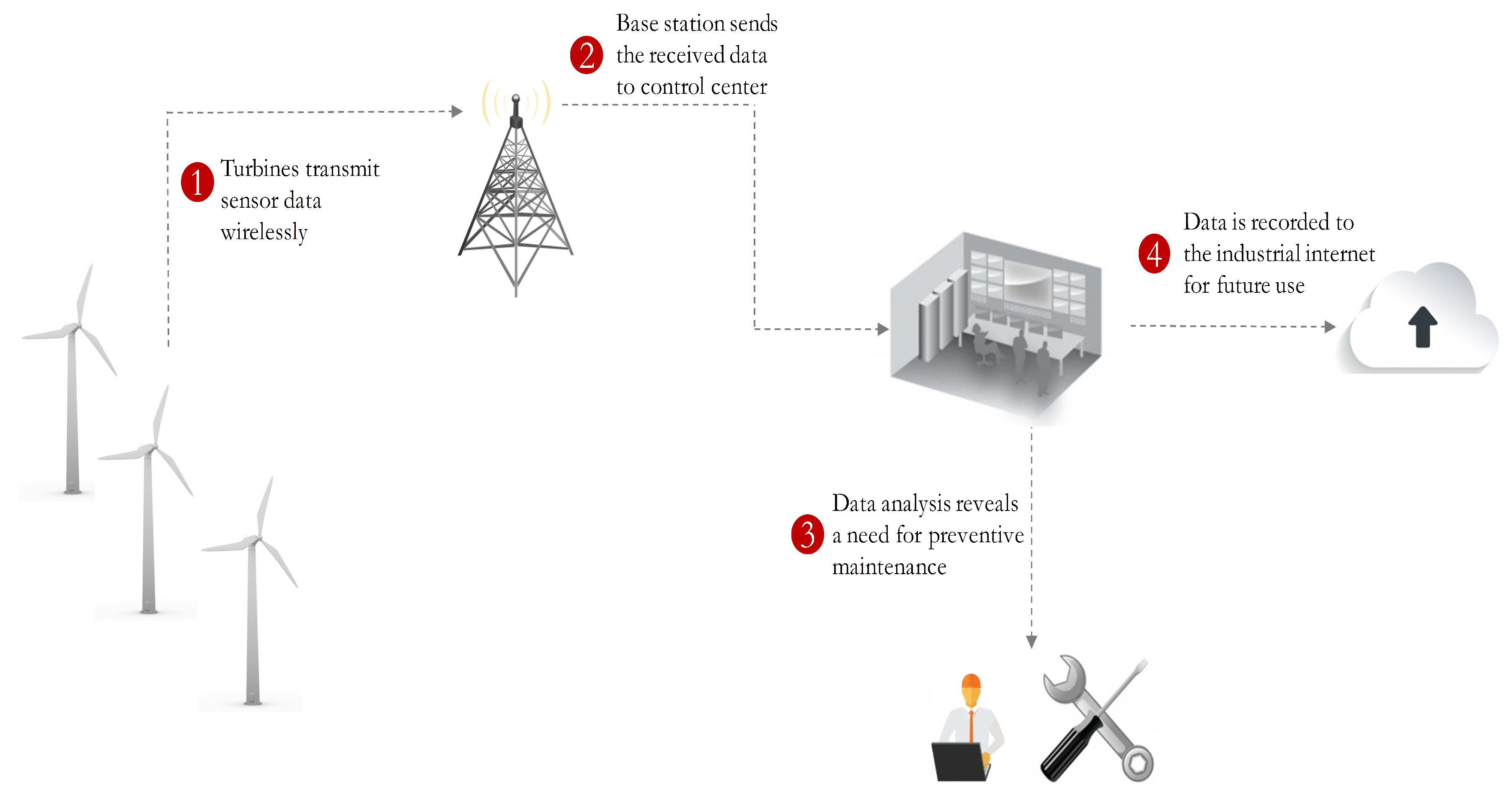
2. IoT Enabled Wind Energy Conversion System and State Space Model

In general, wind farms are situated in remote locations and thus the control centers are typically located several hours away from the wind farms. Remote data communication connectivity through the Internet in the form of an IoT network can help the control centers to monitor the state of a wind turbine and to control a wind turbine’s operation. Due to the remote location of wind turbines, the IoT network connectivity requires wireless networks such as cellular or satellite networks. An integrated scenario comprised of wind turbines and a wireless IoT network [25] is depicted in Figure 1.
A wind turbine system consists of induction generator, rotors, gearbox, and matrix converter [26,27]. The matrix converter connects the induction generator with the power grid and controls the output power delivered to the grid. In this paper, we track the output current components of an induction generator in a wind turbine. We adopt the state space model reported in [28], where a fixed-speed wind turbine is considered. Authors in [28] utilized the current model to characterize the induction generator and the following assumptions were considered for the sake of simplicity: (1) the stator current is assumed to be negative when it flows toward the machine; (2) a synchronous reference frame was considered to derive the equations; (3) the d-axis is 90 deg behind the q-axis (Direct axis (d-axis) is the axis of the stator/rotor’s salient pole and quadrature axis (q-axis) is the axis in quadrature or perpendicular to the stator/rotor’s salient pole.). With the above assumptions, we adopt the linearized state space current model of induction generator, which is described by the following equation:
X ˙ = A X + B U + Γ 𝒩 p
where X = [ i d s i q s i d r i q r ] T is the state of the induction generator, U = [ v d s v q s v d r v q r ] T is control input, Γ is a constant matrix, and 𝒩 p is process noise. We model the process noise as Gaussian noise with zero-mean and covariance matrix Q . In X , i d s and i q s are the stator currents in the d and q axes, respectively; i d r and i q r are the rotor currents in the d and q axes, respectively. In U , v d s and v q s are the stator voltages in the d and q axes, respectively; v d r and v q r are the stator voltages in the d and q axes, respectively. With the specifications of a single-cage induction generator, A and B are characterized by [28,29],
A = ω b X s X r γ R s X r α 1 ω s R r X m β r ω s α 1 ω s R s X r β r ω s R r X m R s X m β s ω s R r X s α 2 ω s β s ω s R s X m α 2 ω s R r X s
B = ω b X s X r γ X r 0 X m 0 0 X r 0 X m X m 0 X s 0 0 X m 0 X s
where ω b , ω s , ω r are base, stator, rotor angular speeds, respectively; s is the slip defined by s = ω s ω r ω s ; R s , R r Stator, rotor resistances, respectively; X s , X r , X m stator, rotor, magnetizing reactances, respectively; α 1 = X s X r s X m 2 , α 2 = X m 2 s X s X r , β s = X m X s ( 1 s ) , β r = X m X r ( 1 s ) , γ = 1 X m 2 X r X s .
For the sake of simplicity, we discretise Equation (1) in the following form [30]:
X ( t + 1 ) = A d X ( t ) + B d U ( t ) + Γ 𝒩 p
where A d and B d are obtained by,
A d = exp ( A Δ t ) ( I ) + A Δ t B d = 0 Δ t exp ( A z ) B d z B Δ t
where Δ t is the step size used for discretization.

3. Proposed Communication Framework

In a wind turbine, different types of sensors are embedded to measure the components of the wind turbine, for example, generated current, voltage, rotor speed, etc. Let 𝒪 i ( t ) , i = 1 , 2 , , N , be the measured state by the i t h sensor of the wind turbine. We define 𝒪 i ( t ) by,
𝒪 i ( t ) = C i X ( t ) + 𝒩 m i ,
where C i is the measurement/sensing matrix of sensor i and 𝒩 m i is the observed noise during the measurement at sensor i. Similar to the process noise, we model the measurement noise as Gaussian noise with zero-mean and co-variance R i . The measured state is sent periodically to the control center for the appropriate action to be taken. Due to the remote placement of wind turbines there often is no direct communication link between a wind turbine and the control center. In most cases, a transmitter in the wind turbine communicates with a nearby base station, from where the message is relayed to the control center. We assume that the communication link between the base station and the control center is reliable as it is part of a fixed backbone network. However, due to the wireless communication channel between the wind turbine and the base station it is challenging to maintain reliable data communication, although reliable communication is highly desirable for accurate state estimation and control applications. To achieve reliable communication between the wind turbine and the base station we propose the following communication strategy. We define the observed state as 𝒪 i ( t ) = [ o i 1 , o i 2 , , o i p ] , where o i j ( t ) is the j t h component of X , which is measured by the i t h sensor. Each component of 𝒪 i ( t ) is mapped and quantized into K bits. The bit block corresponding to component j is represented by b i j ( t ) { 0 , 1 } K . A repeat-accumulate code is then applied over b i j ( t ) to generate a code word c i j ( t ) { 0 , 1 } K η , where η is the rate of the code. All code words are arranged serially to form m i ( t ) = [ c i 1 ( t ) , c i 2 ( t ) , , c i p ( t ) ] . After modulating the m i ( t ) onto the wireless carrier signal, the resultant carrier signal s i ( t ) is then transmitted from the wind turbine to the base station. Let s ^ i ( t ) be the received signal at the base station, which is defined by,
s ^ i ( t ) = s i ( t ) + 𝒩 w ,
where 𝒩 w is the additive white Gaussian noise (AWGN) with zero mean and standard deviation σ w . Upon receiving s ^ i ( t ) , the receiver performs the reverse process (i.e., demodulation, decoding, demapping, etc.) in order to construct the observed state. Let 𝒪 ^ i ( t ) be the reconstructed observed state which corresponds to 𝒪 i ( t ) . The reconstructed observed state 𝒪 ^ i ( t ) is then fed to our proposed fusion algorithm (discussed in Section 4) to track the original state of the wind turbine. The overall communication framework is depicted in Figure 2. In the following, we briefly describe the repeat-accumulate code along with its encoding and decoding procedures.

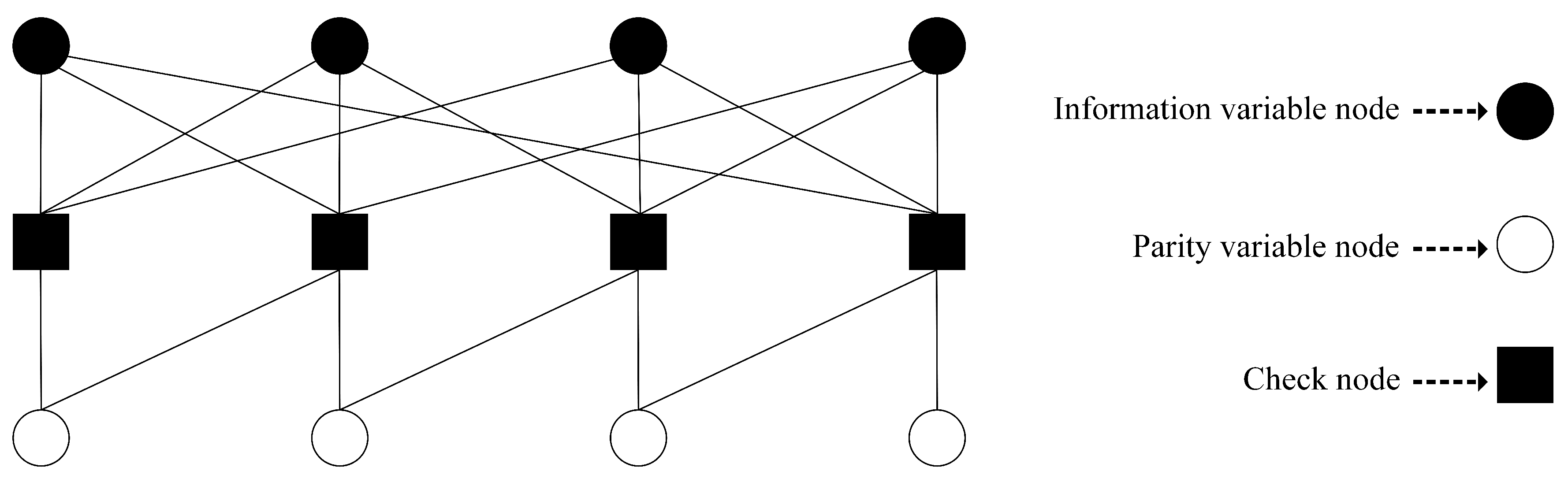
Repeat Accumulate (RA) Codes

Low-density parity-check (LDPC) codes are best known for their capacity approaching performance and low complexity decoding property [31,32]. Repeat accumulate (RA) codes are a special type of LDPC codes which inherit the above properties while allowing low encoding complexity [33,34,35]. Similar to the LDPC codes, RA codes can be represented by a bipartite graph with K information variable nodes, M parity variable nodes, and M check nodes. Each information node represents an information bit, while each check node represents a check equation satisfying the condition that the modulo 2 sum of all the connected nodes will be zero. The value of each parity node, which represents a redundant/parity bit, is generated such that the check equation satisfies the above condition. In an RA code, each information node is connected to more than one check node, while each parity bit node has connection with exactly two check nodes (except the last parity node, which connects to only one check node). We connect the parity bit nodes and the check nodes such that the i t h parity bit node always connects with the check nodes at position i t h and ( i 1 ) t h . The parity/redundant bits or the value of the parity nodes are generated in the following manner. The i t h parity bit node’s value is calculated by performing modulo-2 sum of the information bit nodes that have connection with the i t h check node and the ( i 1 ) t h parity bit node. A RA code is referred to as ( q , a ) -regular code, when each of the information bit node is connected with exactly q check nodes and each of the check nodes is connected with exactly a information bit nodes. A Tanner graph representation of a ( q , a ) = ( 3 , 3 ) regular RA code is depicted in Figure 3. Note that a Tanner graph is equivalent to a binary matrix H of size M × ( K + M ) , where each column and row represent variable and check nodes, respectively and each non zero entry represents a connection between the corresponding variable and check nodes.

Belief Propagation Decoding

A belief propagation (BP) decoding algorithms, which belong to the category of message passing algorithms, is among the best known decoding algorithms over binary input AWGN channels [36]. In a BP decoding algorithm, messages that passed between nodes are represented by log likelihood ratios (LLRs) (see Equations (3)–(5) in the following). Let x m be the m t h bit of a codeword (i.e., m t h variable node in the Tanner graph) and y m be the corresponding channel output. For variable node m, the initial (channel) LLR is given by ([37] [Chapter 2]),
r m = log P ch ( y m | x m = 0 ) P ch ( y m | x m = 1 ) .
For simplicity, we use the following notations to describe the BP decoding algorithm:
  • S v ( m ) → set of variable nodes that have connection/edge with the m t h check node.
  • S c ( m ) → set of check nodes that have connection/edge with the m t h variable node.
  • V n , m ( ) → LLR message sent from variable node m to check node n at iteration .
  • C n , m ( ) → LLR message sent from check node n to variable node m at iteration .
Message from check node:
C n , m ( ) = 2 tanh 1 m S v ( n ) , m m tanh V n , m ( ) 2 .
Message from variable node:
V n , m ( + 1 ) = n S c ( m ) , n n C n , m ( ) + r m .
The above decoding process is initialized by sending the channel LLRs from each variable node to the connected check nodes. After maximum iteration, the max , m t h decoded bit is given by
x ^ m = 0 if n S c ( m ) C n , m ( max ) + r m 0 1 if n S c ( m ) C n , m ( max ) + r m < 0
A successful decoding event can be indicated by summed syndrome ψ , which is defined by ψ = mod 2 ( H x ^ T ) , where mod 2 ( · ) is a modulo-2 operation and x ^ = x ^ 1 , x ^ 2 , , x ^ K + M . ψ = 0 indicates a successful decoding event, while ψ > 0 indicates an unsuccessful decoding event.

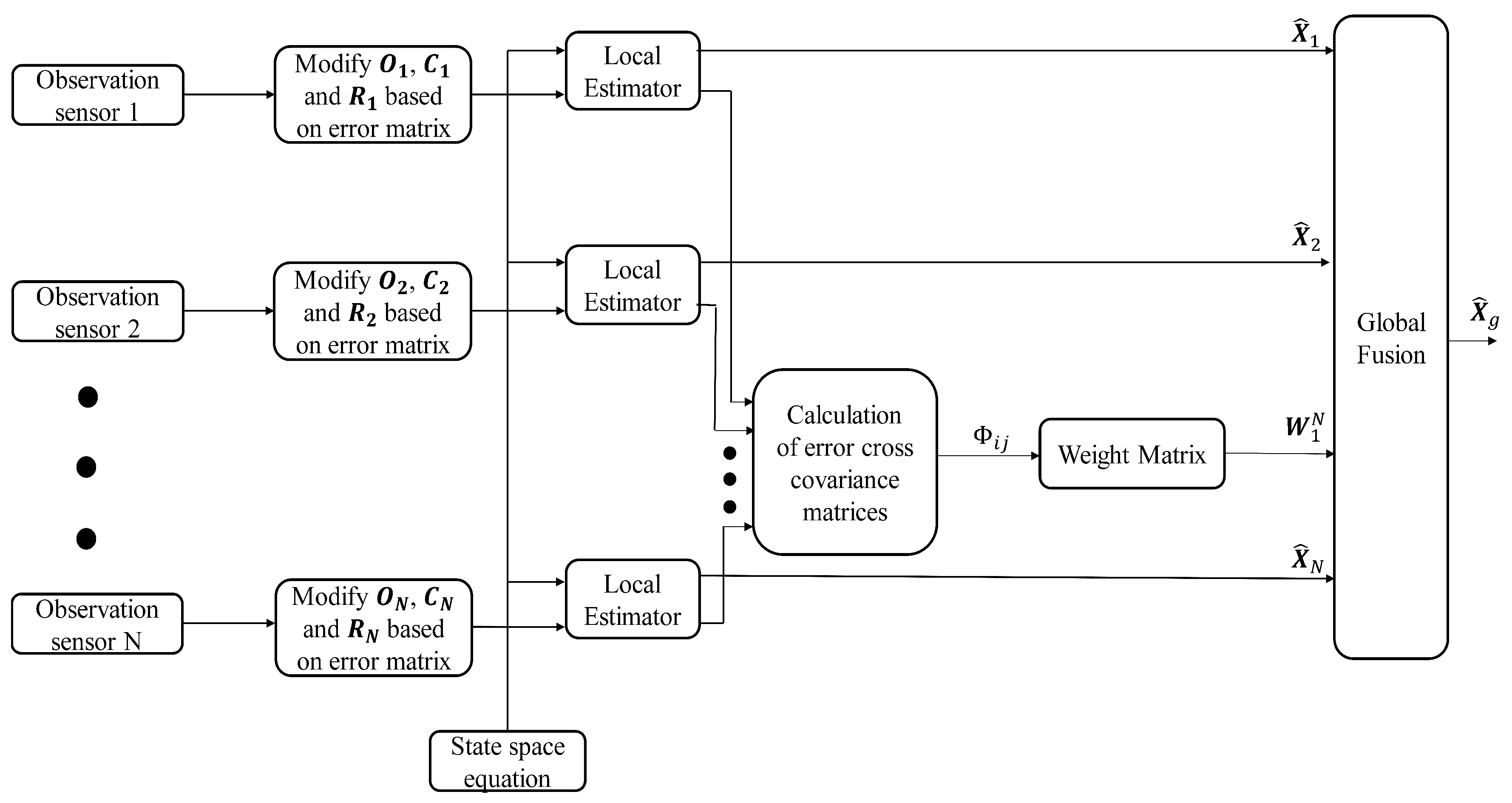
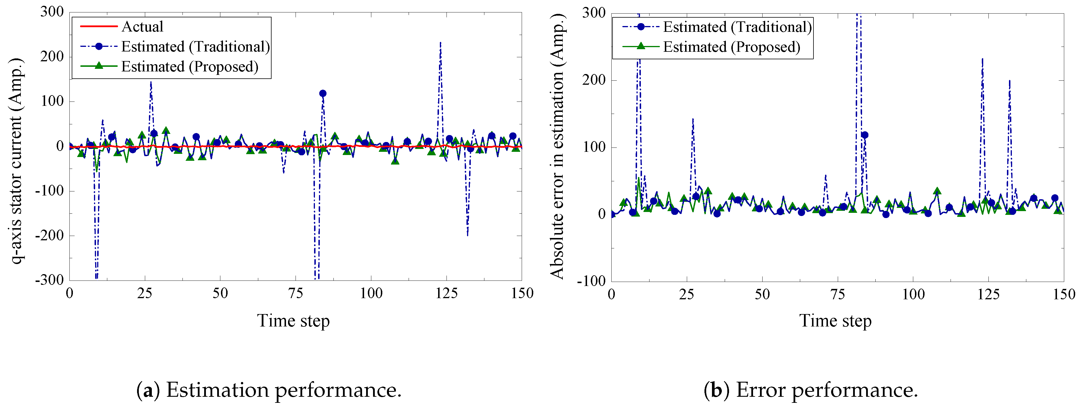
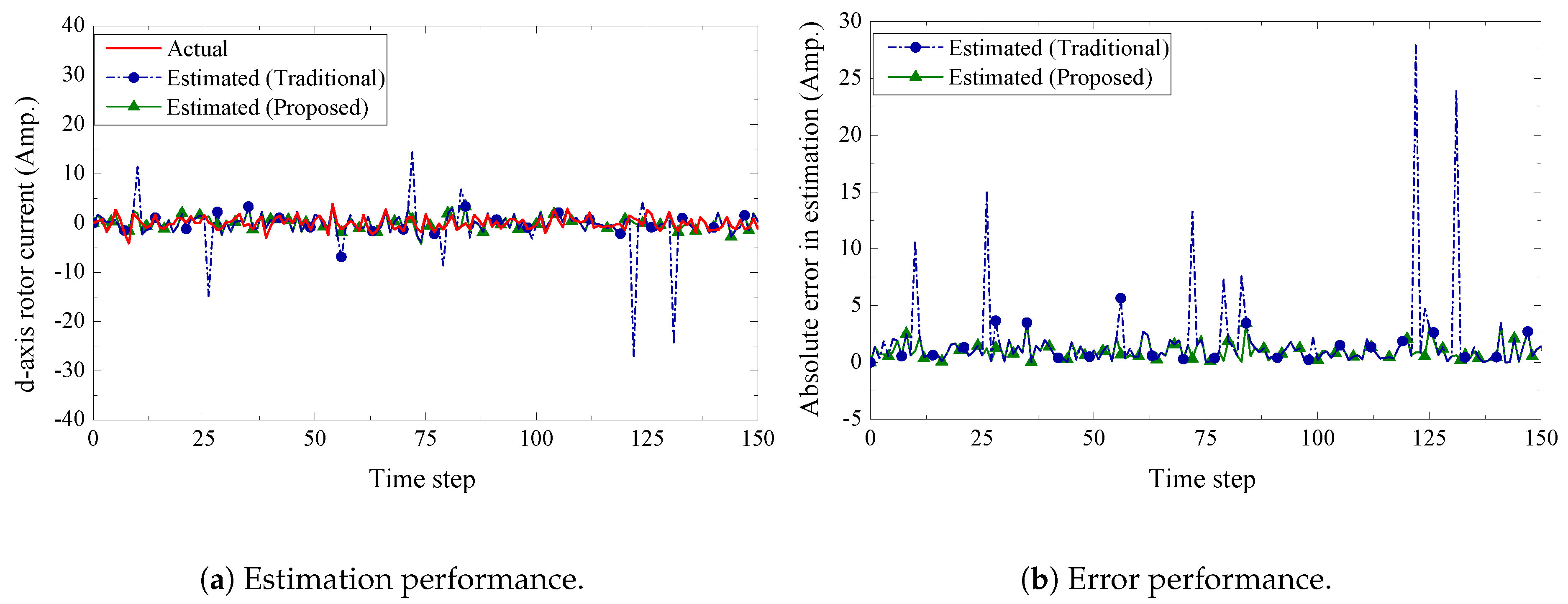
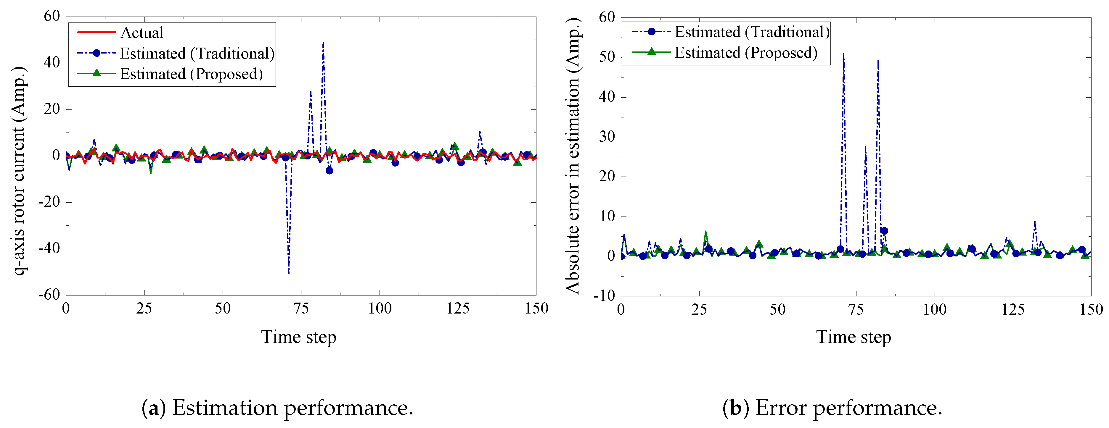
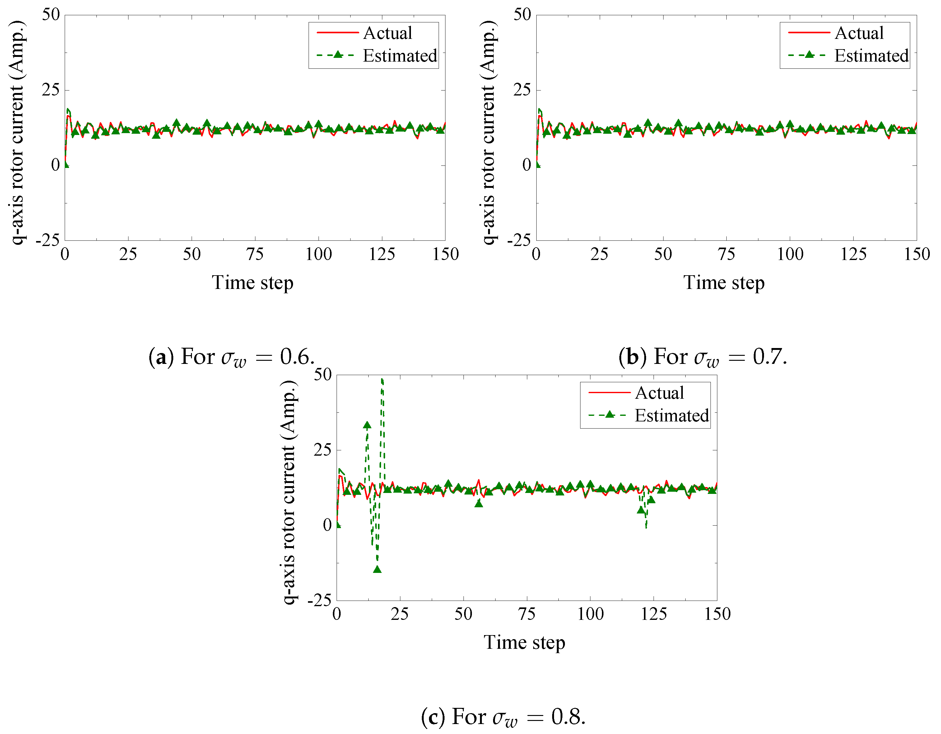
4. Proposed Sensor Fusion Technique

We now present our state estimation with sensor fusion based on a Kalman filter algorithm [38,39]. We illustrate the proposed scheme in the following four steps:
Step 1—Prediction: Let X ^ ( t ) and P ^ ( t ) be the predicted state and co-variance matrix, respectively. According to the Kalman filter algorithm, we calculate X ^ ( t ) and Υ ^ ( t ) by
X ^ i ( t ) = A d X ^ i ( t 1 ) + B d U ( t 1 ) Υ i ( t ) = A d Υ i ( t 1 ) A d T + Q
We denote Υ i ( t ) as the i t h local estimator’s updated co-variance matrix at time step t. Initially we set Υ i ( 0 ) to a predefined value Υ 0 .
Step 2—Modification: We find the summed syndrome value of each component of 𝒪 ^ i ( t ) . We remove the erroneous component from 𝒪 ^ i ( t ) and modify C i and R i accordingly. Let 𝒪 ¯ i ( t ) , C ¯ i ( t ) , and R ¯ i ( t ) be the modified version of 𝒪 ^ i ( t ) , C i and R i , respectively.
Step 3—Update: Let ϵ i ( t ) and 𝒢 i ( t ) be the measurement pre-fit residual and Kalman gain, respectively. We calculate ϵ i ( t ) and 𝒢 i ( t ) by
ϵ i ( t ) = O ¯ i ( t ) C ¯ i ( t ) X ^ i ( t ) 𝒢 i ( t ) = Υ i ( t ) C ¯ i ( t ) T C ¯ i ( t ) Υ i ( t ) C ¯ i ( t ) T + Q
At time step k, co-variance matrix estimate and the updated state estimate are calculated by,
Υ ( t ) = Υ ( t ) 𝒢 ( t ) C ¯ i ( t ) Υ i ( t ) X ^ i ( t ) = X ^ i ( t ) + 𝒢 i ( t ) R ¯ i ( t )
Step 4—Fusion: Let Φ p q ( t ) , p , q { 1 , 2 , , N } be the error cross co-variance between the p t h and the q t h sensors. Φ p q ( t ) is given by
Φ p q ( t | t ) = Υ 0 if t = 0 Υ p ( t ) if m = n I λ 𝒢 p ( t ) C ¯ p ( t ) ] × Otherwise A d Φ p q ( t 1 | t 1 ) A d T + Γ Q Γ T ] × I λ 𝒢 q ( t ) C ¯ q ( t ) ]
where I λ is the identity matrix of size λ × λ and λ is the number of components in X . Following [18,40], optimal fusion based on the linear minimum variance can be written as
X ^ g ( t ) = W 1 ( t ) X ^ 1 ( t ) + W 2 ( t ) X ^ 2 ( t ) + + W N ( t ) X ^ N ( t )
where the matrix weight W ¯ ( t ) is given by
W ¯ ( t ) = Ξ ( t ) 1 T Ξ ( t ) 1
where W ¯ ( t ) = [ W 1 ( t ) , W 2 ( t ) , , W N ( t ) ] T is an λ N × λ matrix, Ξ ( t ) = ( Φ p q ( t ) ) , p , q = 1 , 2 , , N is an λ N × λ N symmetric positive definite matrix, and = [ I λ , , I λ ] T is an λ N × λ matrix. The overall fusion process is shown in Figure 4.

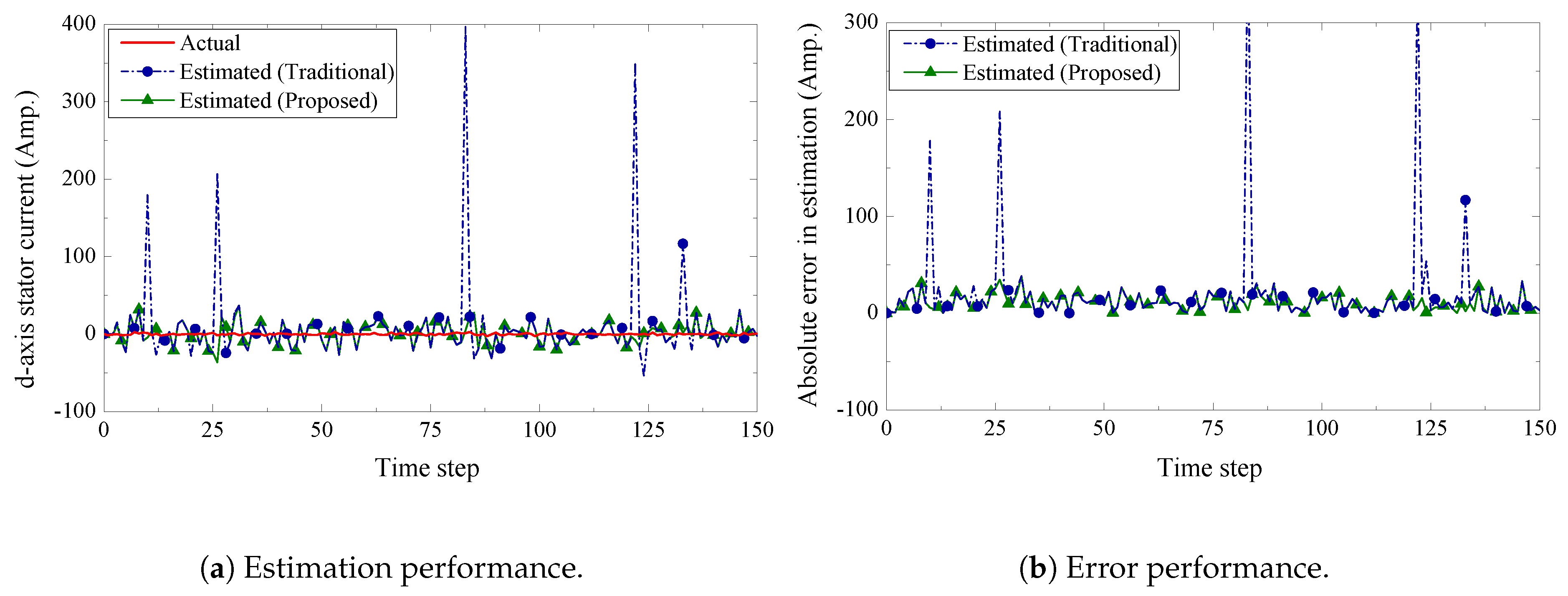
5. Performance Evaluations

In this section, we present the performance of the proposed communication and fusion technique. We also compare the numerical results with a traditional fusion technique [18]. We built a simulation environment in Matlab to evaluate the tracking performance of the wind turbine’s state. The parameters of the induction generator are shown in Table 2. We set the following values for the input parameters: the stator voltage in the d axis is v d s = 0.04 Volt, the stator voltage in the q axis is v q s = 0.99 Volt, the rotor voltage in the d axis is v d r = 0.02 Volt, and the rotor voltage in the q axis is v q r = 0.206 Volt. Note that the above parameters are adopted from the experimental setup reported in [28]. The process’ noise co-variance is set to Q = 0.95 I λ with constant matrix Γ = I λ . For the following results, simulations were carried out for 150 steps with a step size of Δ t = 0.0001 s.
We present the estimation performance of the proposed scheme in Figure 5, Figure 6, Figure 7 and Figure 8. Four sensors are used to measure the four current components of the induction generator with the following measurement matrices C 1 = [ 1 0 0 0 ] , C 2 = [ 0 1 0 0 ] , C 3 = [ 0 0 1 0 ] , C 4 = [ 0 0 0 1 ] . The measurement noise co-variances of the four sensors are set as 1.6 , 1.2 , 1.4 , and 1.6 , respectively. We consider a 32-bits uniform quantizer to map each component of the measured state. We use a rate 1 2 - ( q , a ) = ( 4 , 4 ) repeat-accumulate code over each mapped 32 bit frame and hence each component is represented by a codeword of 64 bits. This codeword is then modulated with BPSK and sent over a wireless channel with noise standard deviation 0.7 . From the results, we observe that the proposed fusion technique can track the state of the wind turbine very closely. As a benchmark, we also present results obtained from a traditional fusion algorithm [18]. We show that our proposed scheme can significantly outperform the traditional estimation approach. In case of an error event due to the wireless transmission, it is expected that the measured state received by the remote receiver will be unreliable. While the traditional fusion algorithm treats all the measured states with the same importance, the proposed algorithm ignores the measured state and gives priority to the observation from the system dynamics. We notice that the traditional fusion algorithm fails to track the state (blue spikes in the figures), which are results of erroneous transmissions. We also investigate the impact of the wireless channel on the estimation performance of the proposed scheme. In Figure 9, we show the estimation performance while varying the channel noise standard deviation σ w . Note that in terms of noise standard deviation, the decoding threshold of the presented ( 4 , 4 ) -RA code is 0.885 . For σ w = 0.6 and σ w = 0.7 , we observe similar estimation performance, which indicates that the wireless channel does not influence the estimation performance when the noise standard deviation is well below the threshold. However, when the noise standard deviation is close to the threshold (for σ w = 0.8 ), we observe inaccuracies in the estimation results.

6. Conclusions

The communication link between wind turbines and control center is often wireless to the remote placement of wind farms. In this paper, we have presented the state estimation of a wind turbine while taking into account the uncertainty of the wireless channel. We have shown an IoT inspired wireless communication framework to monitor the states of the wind turbine. A repeat-accumulate coded communication scheme is presented to tackle the noise induced by the unreliable wireless channel. Moreover, we have proposed an effective fusion algorithm to process and combine the multiple readings from different sensors of a wind turbine. Through simulation results, we have shown that our proposed scheme can track the state of a wind turbine accurately. We have also shown that the estimation performance of the proposed scheme outperforms estimation performance of traditional fusion algorithms. In the future we aim to apply our proposed scheme in a practical test-bed to evaluate the performance for real-world use cases.

Author Contributions

M.N.-A.-R. and M.O.K. performed theoretical investigation and wrote the draft; M.N.-A.-R. and X.L. performed the simulation; D.P. supervised the work and revised the manuscript.

Funding

This work has received funding in part, from the European Union’s Horizon 2020 Research and Innovation Programme under the EDGE COFUND Marie Sklodowska Curie grant agreement No. 713567 and from the Science Foundation Ireland under CONNECT Centre grant no. 13/RC/2077.

Conflicts of Interest

The authors declare no conflict of interest.

References

  1. Moradi, H.; Vossoughi, G. Robust control of the variable speed wind turbines in the presence of uncertainties: A comparison between H? and PID controllers. Energy 2015, 90, 1508–1521. [Google Scholar] [CrossRef]
  2. Najafi Khoshrodi, M.; Jannati, M.; Sutikno, T. A Review of Wind Speed Estimation for Wind Turbine Systems Based on Kalman Filter Technique. Int. J. Electr. Comput. Eng. 2016, 6, 1406–1411. [Google Scholar] [CrossRef]
  3. Xu, L.D.; He, W.; Li, S. Internet of Things in Industries: A Survey. IEEE Trans. Ind. Inf. 2014, 10, 2233–2243. [Google Scholar] [CrossRef]
  4. Zanella, A.; Bui, N.; Castellani, A.; Vangelista, L.; Zorzi, M. Internet of Things for Smart Cities. IEEE Internet Things J. 2014, 1, 22–32. [Google Scholar] [CrossRef]
  5. Al-Fuqaha, A.; Guizani, M.; Mohammadi, M.; Aledhari, M.; Ayyash, M. Internet of Things: A Survey on Enabling Technologies, Protocols, and Applications. IEEE Commun. Surv. Tutor. 2015, 17, 2347–2376. [Google Scholar] [CrossRef]
  6. Berg, J.C.; Miller, K. Sensor Selection for Wind Turbine State Estimation. In Proceedings of the ITEA Live-Virtual-Constructive Conference, Orlando, FL, USA, 1–4 December 2008. [Google Scholar]
  7. Soltani, M.N.; Knudsen, T.; Svenstrup, M.; Wisniewski, R.; Brath, P.; Ortega, R.; Johnson, K. Estimation of Rotor Effective Wind Speed: A Comparison. IEEE Trans. Control Syst. Technol. 2013, 21, 1155–1167. [Google Scholar] [CrossRef]
  8. Ritter, B.; Schild, A.; Feldt, M.; Konigorski, U. The design of nonlinear observers for wind turbine dynamic state and parameter estimation. J. Phys. Conf. Ser. 2016, 753, 52029. [Google Scholar] [CrossRef] [Green Version]
  9. Petar, M.; Petrovi, V.; Baotic, M. Dual Kalman Estimation of Wind Turbine States and Parameters. In Proceedings of the International Conference on Process Control, Tatranska Lomnica, Slovakia, 14–17 June 2011; pp. 85–91. [Google Scholar]
  10. Bourlis, D.; Bleijs, J.A.M. A wind speed estimation method using adaptive Kalman filtering for a variable speed stall regulated wind turbine. In Proceedings of the 2010 IEEE 11th International Conference on Probabilistic Methods Applied to Power Systems, Singapore, 14–17 June 2010; pp. 89–94. [Google Scholar] [CrossRef]
  11. Miranda-Blanco, B.N.; Díaz-Dorado, E.; Carrillo, C.; Cidrás, J. State estimation for wind farms including the wind turbine generator models. Renew. Energy 2014, 71, 453–465. [Google Scholar] [CrossRef]
  12. Sudev, P.; Anita, J.P.; Sudheesh, P. Nonlinear state estimation of wind turbine. In Proceedings of the International Conference on Advances in Computing, Communications and Informatics (ICACCI), Udupi, India, 13–16 September 2017; pp. 354–358. [Google Scholar] [CrossRef]
  13. Yu, S.; Fernando, T.; Emami, K.; Iu, H.H.C. Dynamic State Estimation Based Control Strategy for DFIG Wind Turbine Connected to Complex Power Systems. IEEE Trans. Power Syst. 2016. [Google Scholar] [CrossRef]
  14. Yu, S.; Emami, K.; Fernando, T.; Iu, H.H.C.; Wong, K.P. State Estimation of Doubly Fed Induction Generator Wind Turbine in Complex Power Systems. IEEE Trans. Power Syst. 2016, 31, 4935–4944. [Google Scholar] [CrossRef]
  15. Prajapat, G.P.; Bhui, P.; Senroy, N.; Kar, I.N. Modelling and estimation of gear train backlash present in wind turbine driven DFIG system. IET Gener. Transm. Distrib. 2018, 12, 3527–3535. [Google Scholar] [CrossRef]
  16. Shahriari, S.A.A.; Raoofat, M.; Dehghani, M.; Mohammadi, M.; Saad, M. Dynamic state estimation of a permanent magnet synchronous generator-based wind turbine. IET Renew. Power Gener. 2016, 10, 1278–1286. [Google Scholar] [CrossRef]
  17. Shahinzadeh, H.; Moradi, J.; Gharehpetian, G.B.; Nafisi, H.; Abedi, M. IoT Architecture for Smart Grids. In Proceedings of the 2019 IEEE International Conference on Protection and Automation of Power System (IPAPS), Tehran, Iran, 8–9 January 2019; pp. 22–30. [Google Scholar] [CrossRef]
  18. Sun, S.L.; Deng, Z.L. Multi-sensor optimal information fusion Kalman filter. Automatica 2004, 40, 1017–1023. [Google Scholar] [CrossRef]
  19. Deng, Z.L.; Gao, Y.; Mao, L.; Li, Y.; Hao, G. New approach to information fusion steady-state Kalman filtering. Automatica 2005, 41, 1695–1707. [Google Scholar] [CrossRef]
  20. Chen, B.; Hu, G.; Ho, D.W.C.; Zhang, W.A.; Yu, L. Distributed Robust Fusion Estimation with Application to State Monitoring Systems. IEEE Trans. Syst. Man Cybern. Syst. 2017, 47, 2994–3005. [Google Scholar] [CrossRef]
  21. Tian, T.; Sun, S.; Li, N. Multi-sensor information fusion estimators for stochastic uncertain systems with correlated noises. Inf. Fusion 2016, 27, 126–137. [Google Scholar] [CrossRef]
  22. Chen, B.; Hu, G.; Ho, D.W.; Yu, L. A New Approach to Linear/Nonlinear Distributed Fusion Estimation Problem. IEEE Trans. Autom. Control 2019, 64, 1301–1308. [Google Scholar] [CrossRef]
  23. Chen, B.; Ho, D.W.C.; Zhang, W.A.; Yu, L. Networked Fusion Estimation With Bounded Noises. IEEE Trans. Autom. Control 2017, 62, 5415–5421. [Google Scholar] [CrossRef]
  24. Ma, J.; Sun, S. Distributed fusion filter for networked stochastic uncertain systems with transmission delays and packet dropouts. Signal Process. 2017, 130, 268–278. [Google Scholar] [CrossRef]
  25. Froese, M. Talking with Turbines through the Internet of Things. 2016. Available online: https://www.windpowerengineering.com/wind-farm-networks/talking-turbines-internet-things/ (accessed on 27 March 2019).
  26. Masoud Barakati, S. Modeling and Controller Design of a Wind Energy Conversion System Including a Matrix Converter. 2008, p. 264. Available online: http://hdl.handle.net/10012/3786 (accessed on 27 March 2019).
  27. Barakati, S.; Kazerani, M.; Aplevich, J. Maximum Power Tracking Control for a Wind Turbine System Including a Matrix Converter. IEEE Trans. Energy Convers. 2009, 24, 705–713. [Google Scholar] [CrossRef]
  28. Ugalde-Loo, C.E.; Ekanayake, J.B.; Jenkins, N. State-Space Modeling of Wind Turbine Generators for Power System Studies. IEEE Trans. Ind. Appl. 2013, 49, 223–232. [Google Scholar] [CrossRef]
  29. Ugalde-Loo, C.E.; Ekanayake, J.B. State-space modelling of variable-speed wind turbines: A systematic approach. In Proceedings of the IEEE International Conference on Sustainable Energy Technologies (ICSET), Paris, France, 6–9 December 2010; pp. 1–6. [Google Scholar] [CrossRef]
  30. Noor-A-Rahim, M.; Khyam, M.O.; Ali, G.G.M.N.; Liu, Z.; Pesch, D.; Chong, P.H.J. Reliable State Estimation of an Unmanned Aerial Vehicle Over a Distributed Wireless IoT Network. IEEE Trans. Reliab. 2019, 1–9. [Google Scholar] [CrossRef]
  31. Chung, S.-Y.; Forney, G.; Richardson, T.; Urbanke, R. On the design of low-density parity-check codes within 0.0045 dB of the Shannon limit. IEEE Commun. Lett. 2001, 5, 58–60. [Google Scholar] [CrossRef] [Green Version]
  32. Ten Brink, S.; Kramer, G.; Ashikhmin, A. Design of Low-Density Parity-Check Codes for Modulation and Detection. IEEE Trans. Commun. 2004, 52, 670–678. [Google Scholar] [CrossRef]
  33. Ten Brink, S.; Kramer, G. Design of repeat-accumulate codes for iterative detection and decoding. IEEE Trans. Signal Process. 2003, 51, 2764–2772. [Google Scholar] [CrossRef]
  34. Noor-A-Rahim, M.; Zhang, N.; Wang, S. Performance estimation of finite-length repeat–accumulate codes. IET Commun. 2015, 9, 1902–1905. [Google Scholar] [CrossRef]
  35. Noor-A-Rahim, M.; Khyam, M.O.; Guan, Y.L.; Ali, G.G.N.; Nguyen, K.D.; Lechner, G. Delay-Universal Channel Coding with Feedback. IEEE Access 2018. [Google Scholar] [CrossRef]
  36. Chung, S.Y.; Richardson, T.J.; Urbanke, R.L.; Chung, S.Y.; Richardson, T.J.; Urbanke, R.L. Analysis of sum-product decoding of low-density parity-check codes using a {Gaussian} approximation. IEEE Trans. Inform. Theory 2001, 47, 657–670. [Google Scholar] [CrossRef]
  37. Johnson, S.J. Iterative Error Correction: Turbo, Low-Density Parity-Check and Repeat-Accumulate Codes; Cambridge University Press: Cambridge, UK, 2010. [Google Scholar]
  38. Simon, D. Kalman filtering with state constraints: A survey of linear and nonlinear algorithms. IET Control Theory Appl. 2010, 4, 1303–1318. [Google Scholar] [CrossRef]
  39. Faragher, R. Understanding the Basis of the Kalman Filter Via a Simple and Intuitive Derivation [Lecture Notes]. IEEE Signal Process. Mag. 2012, 29, 128–132. [Google Scholar] [CrossRef]
  40. Sun, S.l. Multi-sensor optimal information fusion Kalman filters with applications. Aerosp. Sci. Technol. 2004, 8, 57–62. [Google Scholar] [CrossRef]
Figure 1. Use of Internet of Things (IoT) network for transmitting data from turbines to control center and technicians.
Sensors 19 01566 g001
Figure 2. Communication framework of multi-sensor wind turbine.
Sensors 19 01566 g002
Figure 3. A Tanner graph representation of a repeat accumulate code with ( q , a ) = ( 3 , 3 ) . In the graph, filled and unfilled circle nodes represent the information and parity bits, respectively, while rectangular nodes represent check equations.
Sensors 19 01566 g003
Figure 4. Block diagram of proposed sensor fusion technique.
Sensors 19 01566 g004
Figure 5. d-axis stator current estimation and error performance.
Sensors 19 01566 g005
Figure 6. q-axis stator current estimation and error performance.
Sensors 19 01566 g006
Figure 7. d-axis rotor current estimation and error performance.
Sensors 19 01566 g007
Figure 8. q-axis rotor current estimation and error performance.
Sensors 19 01566 g008
Figure 9. Impact of wireless channel quality on estimation performance.
Sensors 19 01566 g009
Table 1. Comparison of different works on state estimation of wind turbine.
WorksType of Wind TurbineFilter TypeSensor FusionImpact of Wireless ChannelError Correction Technique
Berg et al. [6]GenericLinear KalmanNoNoNo
Ritter et al. [8]GenericLinear KalmanNoNoNo
Petar et al. [9]GenericExtended KalmanNoNoNo
Bourlis et al. [10]GenericAdaptive KalmanNoNoNo
Blanco et al. [11]GenericExtended KalmanNoNoNo
Sudev et al. [12]GenericParticle filterNoNoNo
Yu et al. [13]DFIGUnscented KalmanNoNoNo
Yu et al. [14]DFIGUnscented KalmanNoNoNo
Prajapat et al. [15]DFIGUnscented KalmanNoNoNo
Shahriari et al. [16]PMSGExtended KalmanNoNoNo
This workGenericLinear KalmanYesYesYes
Table 2. Induction Generator Parameters.
ParameterValue
Base frequency10 Hz
Stator frequency15 Hz
Rotor frequency15 Hz
Resistance of stator0.004 Ω
Resistance of rotor0.005 Ω
Reactance of stator0.09 Ω
Reactance of rotor0.08 Ω
Magnetizing reactance3.95 Ω

