An Enhanced Lightweight Dynamic Pseudonym Identity Based Authentication and Key Agreement Scheme Using Wireless Sensor Networks for Agriculture Monitoring


Abstract
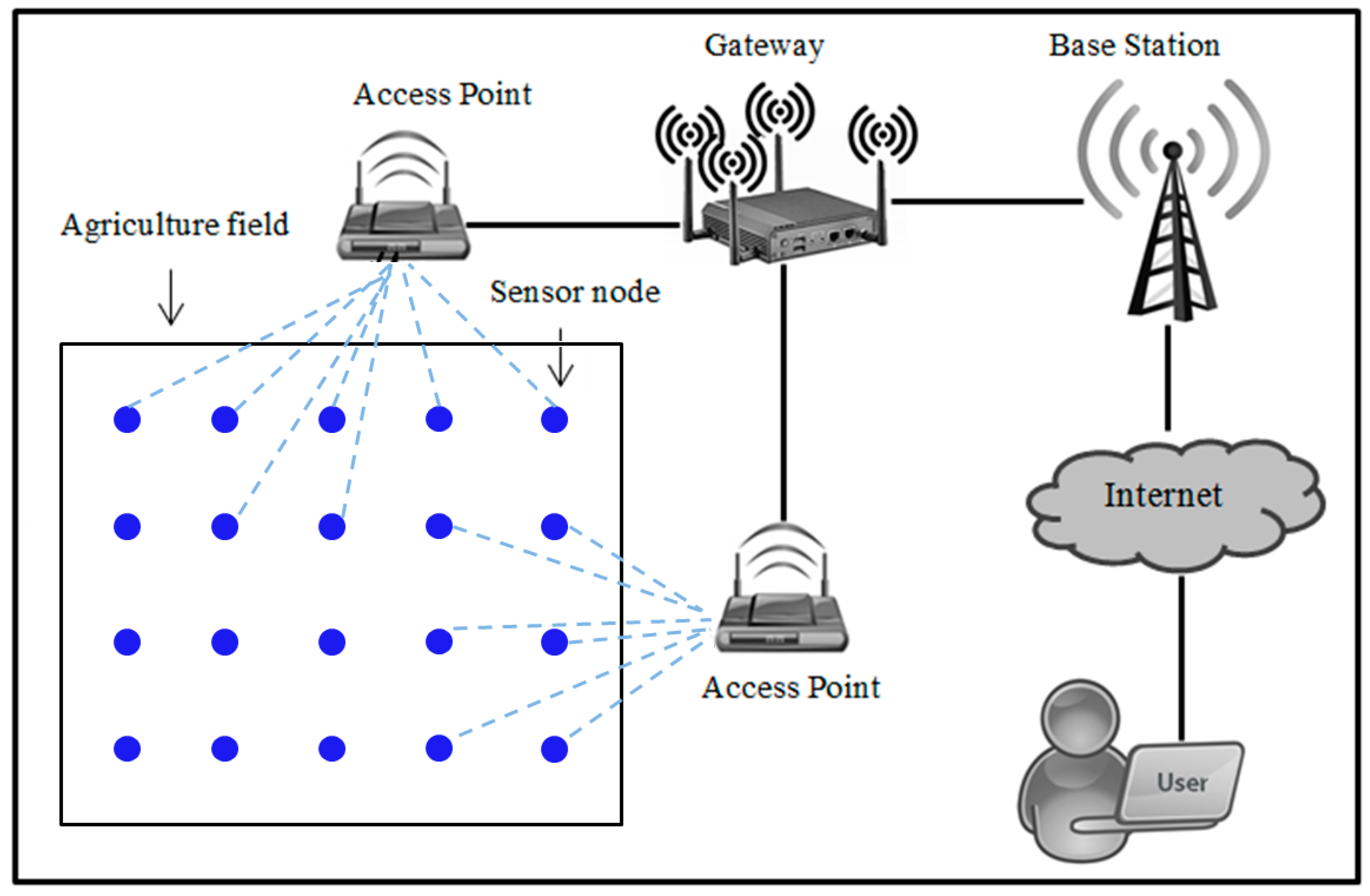
:1. Introduction
1.1. Literature Reviews
1.2. Motivation and Contributions
2. Preliminary
2.1. The Importance and Advantage of Ali et al.’s Scheme
2.2. Ali et al.’s Scheme
2.2.1. System Setup Phase
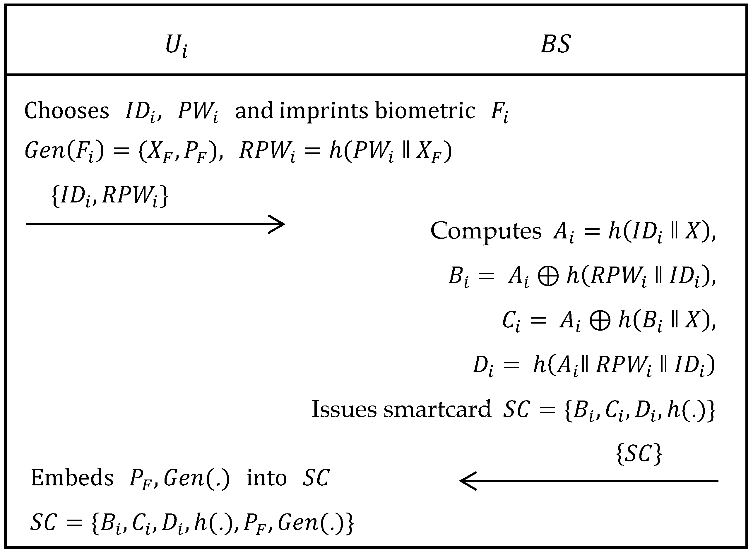
2.2.2. User/Agriculture Professional Registration Phase
| Step 1: | The selects his/her own identity , password and imprints biometric on the sensor device and then computes , , where is a generate function of fuzzy extractor and are, respectively, secret and public keys. Now, sends to via trustworthy channel. |
| Step 2: | When obtained the registration request from , firstly calculates , , and Afterwards, issues a smartcard having parameters, i.e., and sends it to via the same channel. |
| Step 3: | After obtaining the smartcard from , embeds and in the memory of smartcard, i.e., . |
2.2.3. Login Phase
| Step 1: | The inserts his/her own smartcard into card reader and inputs , and also imprints on a sensor device. Now, the card reader computes , = , = , = ⊕ , = , = ⊕ and verifies if equals . If this verification holds then the system continues the process. Otherwise, the session is terminated. |
| Step 2: | Now, generates a random nonce and enumerates , , and sends to via public channel. |
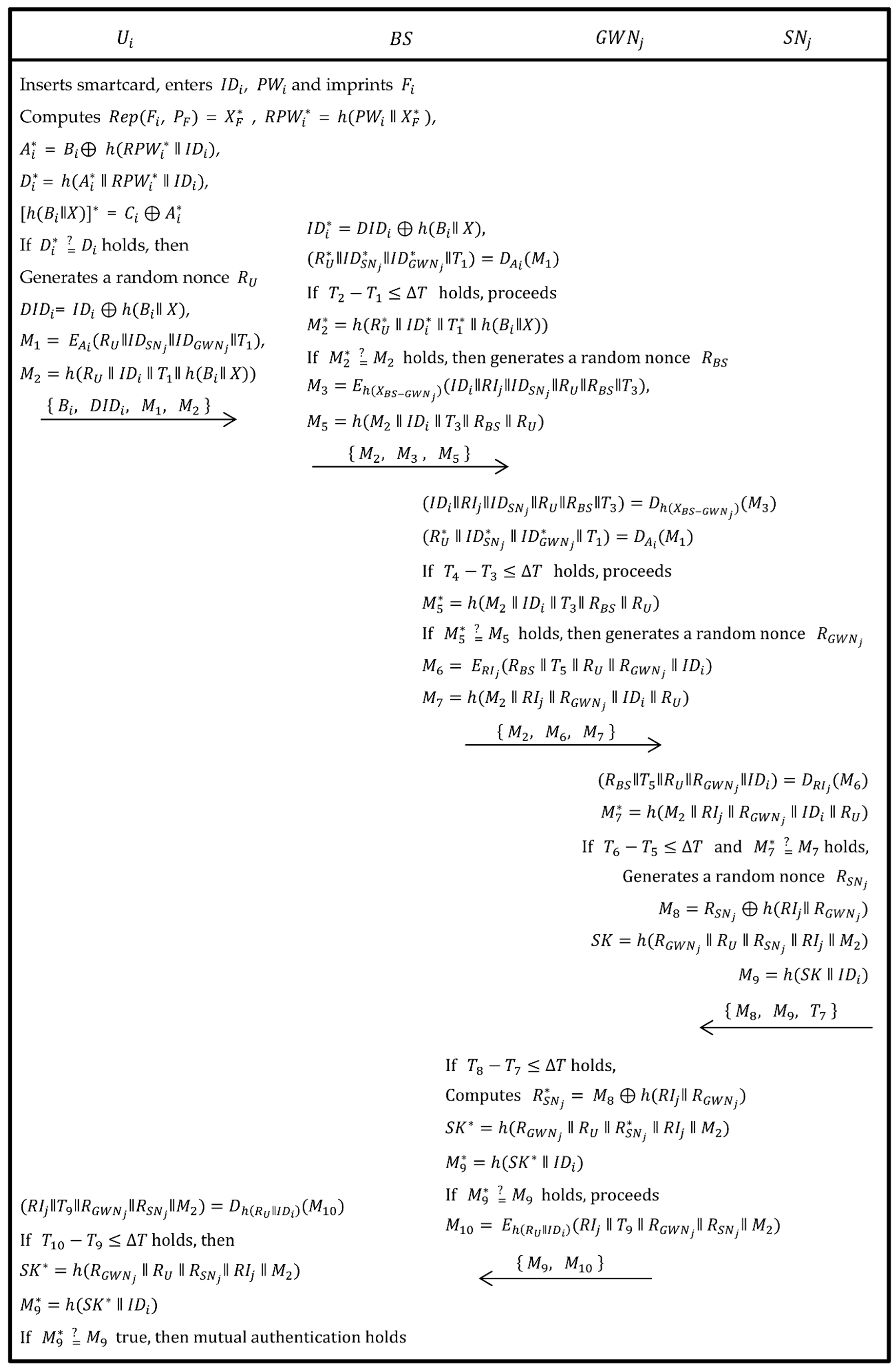
2.2.4. Authentication and Session Key Agreement Phase
| Step 1: | Upon obtaining the message from , the computes , and checks if holds. If this does not true, then session expires. Otherwise, computes and verifies if equals or not. If it holds, then is legal and goes to next step. Otherwise, the session is rejected. |
| Step 2: | Now, the produces a random nonce and computes , and then sends to via public channel. |
| Step 3: | After getting request message from , the computes and , then checks if two condition and hold. If both conditions are true then it proceeds further. Otherwise, the session is terminated. |
| Step 4: | Now, the generates a random nonce and calculates , and then sends to . |
| Step 5: | Upon obtaining the message from , the computes , and then verifies if two conditions and hold. If both are true, then goes to the next step, Otherwise, the session is terminated. |
| Step 6: | Now, the generates a random nonce , computes , , and sends to via public channel. |
| Step 7: | After getting the message from , firstly verifies if holds. If true, the process continues. Otherwise, the session expires. Then, calculates , and , then checks if . If it holds, the next step proceeds. Otherwise, the session is terminated. |
| Step 8: | The computes and sends to via public channel. |
| Step 9: | After getting the message from , computes and verifies if holds. If it holds, the next step proceeds. |
| Step 10: | The calculates =, and checks if holds. If it holds, mutual-authentication and session-key agreement holds. |
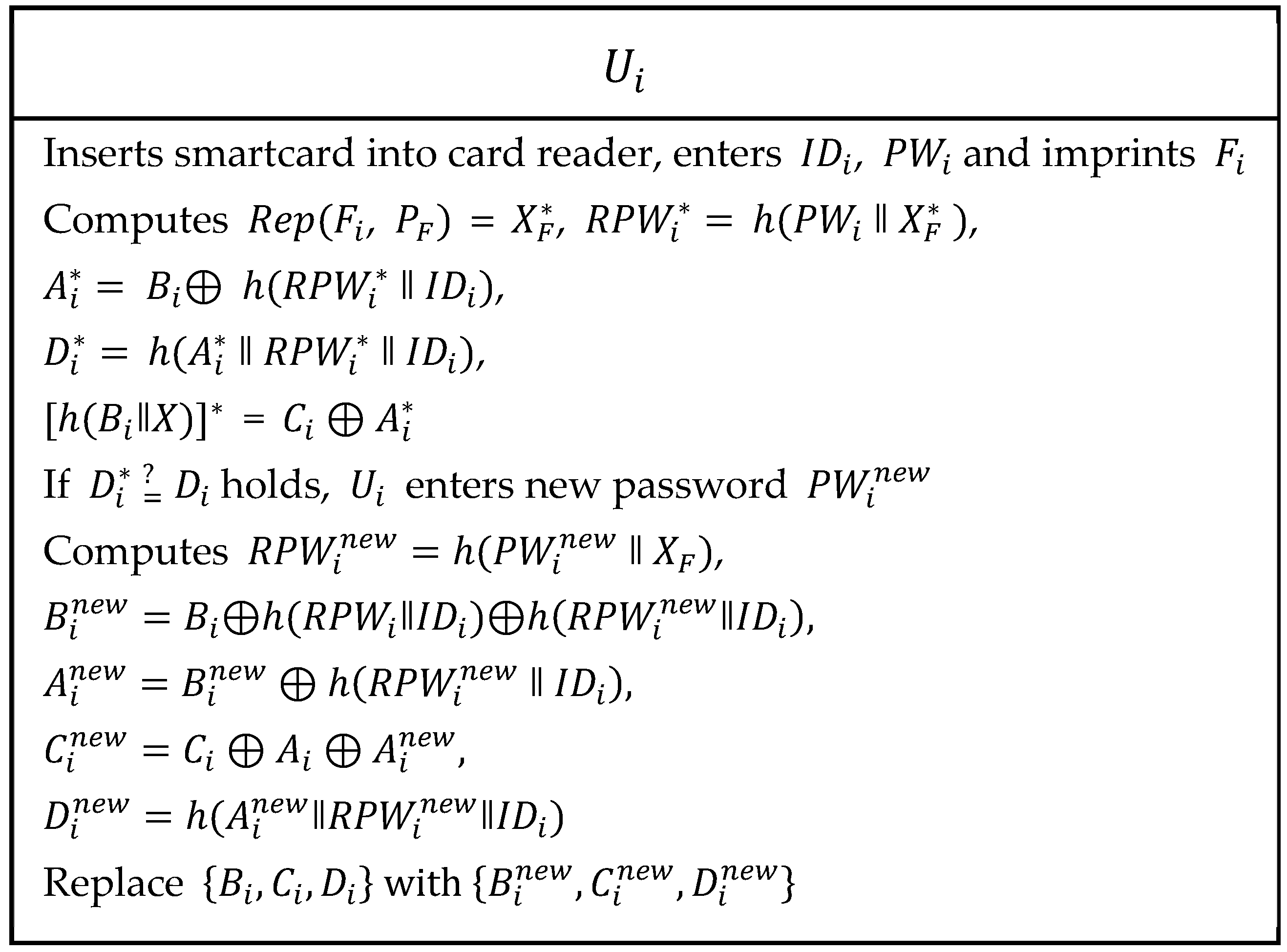
2.2.5. Password Updates or Change Phase
| Step 1: | The inserts his/her own smartcard into the card reader and enters , and imprints on a sensor device. Now, the card reader computes , = , , ⊕ , , = ⊕ and verifies if . If this verification holds, then continues the process. Otherwise, the session is terminated. |
| Step 2: | The enters new password and computes , ⊕⊕, , and . Then, are replaced with . |
2.2.6. Dynamic Node Addition Phase
2.3. Weaknesses of Ali et al.’s Scheme
2.3.1. Violation of User Traceability
2.3.2. Insider Attack
Violation of User Anonymity
Sensor Node Impersonation Attack
Perfect Forward Secrecy Attack
Violation of Session Key Security
2.3.3. Denial of Services as a Service in Authentication and Key Agreement Phase
3. Proposed Authentication and Key-Agreement Scheme Using WSNs for Agriculture Monitoring
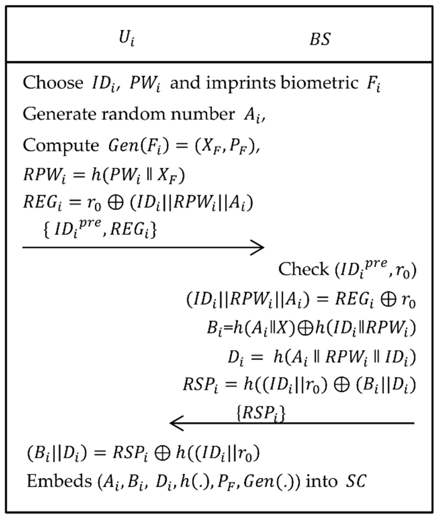
3.1. User/Agriculture Professional Registration Phase
| Step 1: | The selects his/her own identity , password , and imprints biometric on the sensor device and then computes , , where is a generate function of fuzzy extractor and are secret and public key respectively. Now, computes and sends to . |
| Step 2: | When the registration request is received from , if successfully verifies that () is in ’s storage and has not been registered, then computes , and . Afterwards, computes and sends {} to . |
| Step 3: | After receiving the response from , computes , and embeds and in the memory of . |
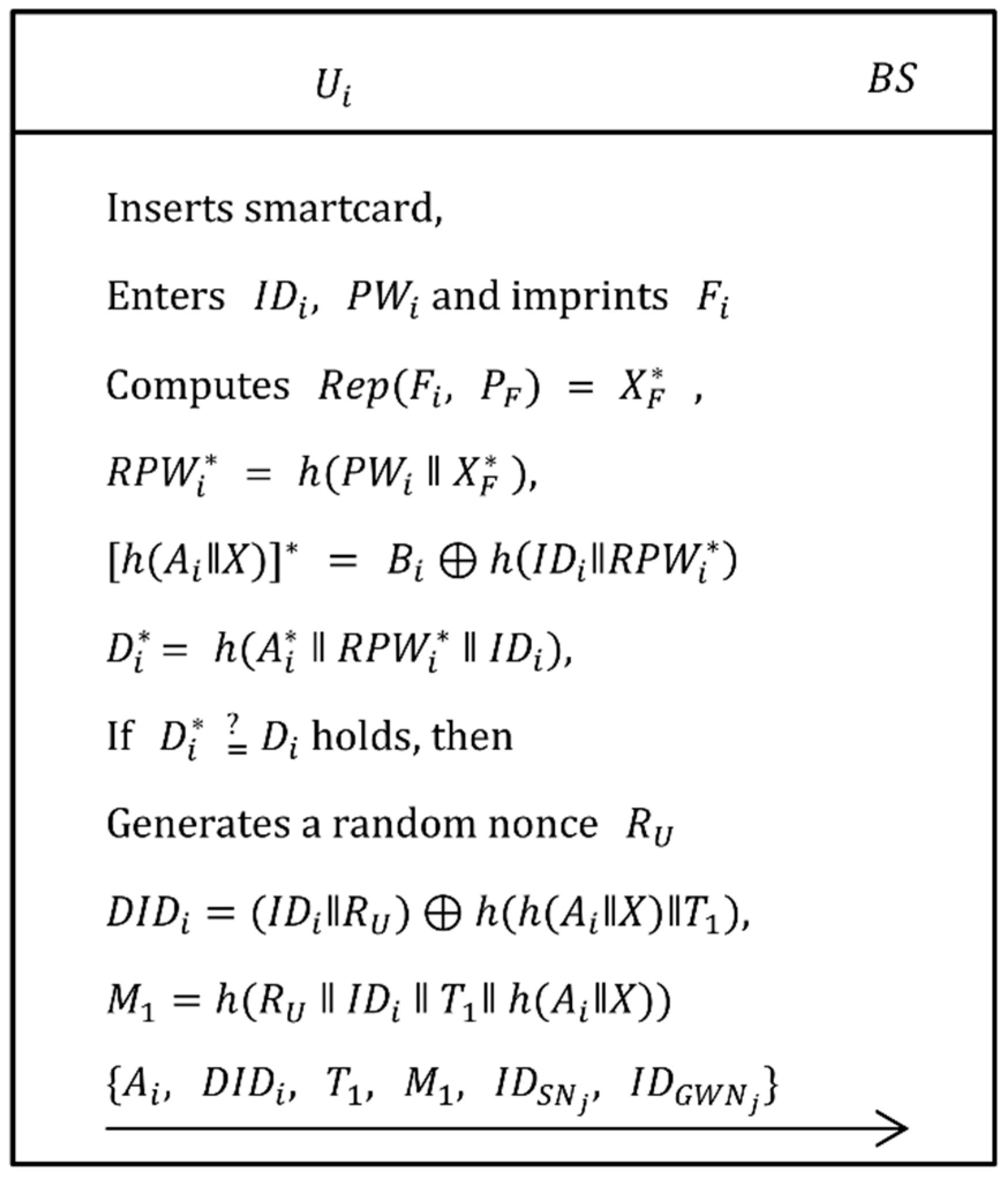
3.2. Login Phase
| Step 1: | The inserts his/her own smartcard into card reader, inputs , and imprints his/her biometric on sensor device. Now, the card reader computes , = , = , = , = and verifies if equals . If the verification holds, the system continues to process the request. Otherwise, the session is terminated. |
| Step 2: | Now, generates a random nonce , computes and , then send to via public channel. |
3.3. Authentication and Session Key Agreement Phase
| Step 1: | Upon obtaining the message from , the checks if holds. If this does not true then session expires. Otherwise, calculates and computes , then verifies if equals or not. If this holds, goes to next step. Otherwise, the session is rejected. |
| Step 2: | Now, generates a random nonce and computes a new , where = Then, computes =⊕, , and ⊕ and sends to via public channel. |
| Step 3: | After getting the request message from , the checks if holds. If this does not true then session expires. Otherwise, calculates and , then checks if holds. If the condition is true then it proceeds further. Otherwise, the session is terminated. |
| Step 4: | Now, the generates a random nonce , calculates = and , then sends to . |
| Step 5: | Upon obtaining the message from , the checks if holds. If this does not true then session expires. Otherwise, calculates , and . Then, verifies if holds. If the condition is true then it proceeds further. Otherwise, the session is terminated. |
| Step 6: | Now, the generates a random nonce , computes , and . Then, sends to . |
| Step 7: | Upon receiving the message from , firstly verifies if holds. If this is not true then the session expires. Otherwise, calculates , and , then checks if holds. If the condition is true then further is proceeded. Otherwise, the session is terminated. |
| Step 8: | The computes and . Then, sends to . |
| Step 9: | Upon receiving the message from , firstly verifies if holds. If this does not true then session expires. Otherwise, computes =⊕, =, , and verifies if holds. If the condition is true then mutual authentication and session key agreement holds. Otherwise, the session is terminated. |
| Step 10: | The computes and . Then, replaces with , , , respectively. |
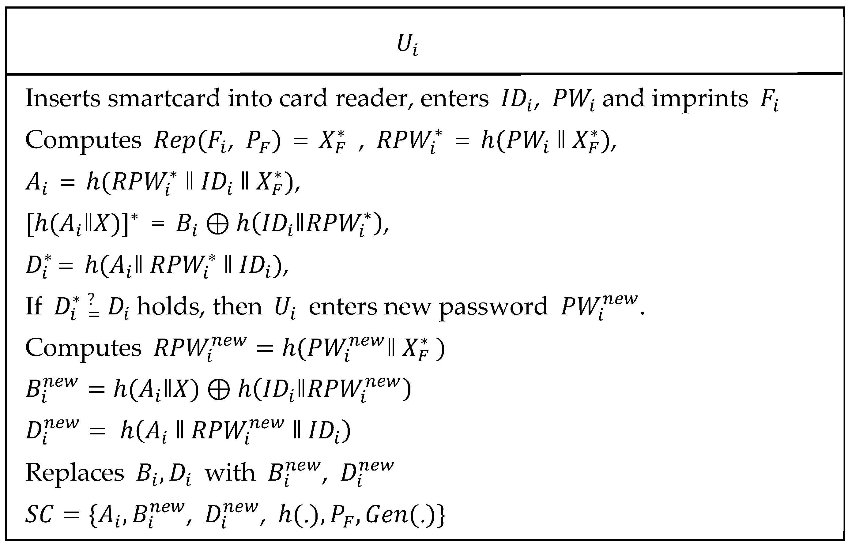
3.4. Password Updates or Change Phase
| Step 1: | The user inserts his/her own smartcard into card reader and enters , and imprints on sensor device. The card reader computes , = , , , = and . Then, verifies if holds. If condition is true then further is proceeded. Otherwise, the session is terminated. |
| Step 2: | The enters new password and computes , and . Then, are replaced with , respectively. |
4. Security Analysis
4.1. Authentication Proof of the Proposed Scheme Using BAN Logic
4.1.1. Basic Rules of BAN Logic
- Rule 1. Message-meaning rule:If the entity believes that the secret is shared with and sees message is encrypted using , then believes that once said .
- Rule 2. Jurisdiction rule:If the entity believes that has jurisdiction over and believes , then believes that is true.
- Rule 3. Nonce-verification rule:If the entity believes that is fresh and the entity once said , then believes that believes .
- Rule 4. Session key rule:If the entity believes that is fresh and believes , then believes the secret that is shared between both entities and .
- Rule 5. Freshness-conjuncatenation rule:If the entity believes that is fresh, then believes the freshness of .
4.1.2. Goals
- Goal 1:
- Goal 2:
- Goal 3:
- Goal 4:
- Goal 5:
- Goal 6:
- Goal 7:
- Goal 8:
- Goal 9:
- Goal 10:
4.1.3. Idealized Form
- Message 1., , , , , :
- Message 2., , , , , :
- Message 3. ( , , , , , , :
- Message 4. (, , , , :
- Message 5. ( , , , :
4.1.4. Assumptions
- A1: | #(, , , )
- A2: | #(, )
- A3: | #(, , , )
- A4: | #(, , , )
- A5: |
- A6: |
- A7: |
- A8: |
- A9: |
- A10: |
- A11: |
- A12: |
- A13: |
- A14: |
4.1.5. Verification
| V5: | | Goal1 |
| V6: | | | Goal2 |
| V11: | | Goal3 |
| V12: | | | Goal4 |
| V17: | | Goal5 |
| V18: | | | Goal6 |
| V23: | | Goal7 |
| V24: | | | Goal8 |
| V30: | | Goal9 |
| V31: | | | Goal10 |
4.2. Informal Security Analysis
4.2.1. User Anonymity
4.2.2. User Traceability
4.2.3. Three-Factor Security
4.2.4. Session Key Security
4.2.5. Perfect Forward Secrecy Attack
4.2.6. Sensor Node Impersonation Attack
4.2.7. Gateway Node Impersonation Attack
4.2.8. User/Agriculture Impersonation Attack
4.2.9. Offline Password Guessing Attack
4.2.10. Replay Attack
4.2.11. Insider Attack
5. Performance and Functionality Comparisons
5.1. Security Functionality Comparisons
5.2. Performance Comparisons
6. Conclusions
Author Contributions
Funding
Acknowledgments
Conflicts of Interest
References
- Arjun, K.M. Indian agriculture—Status, importance and role in Indian economy. Int. J. Res. Agric. Food Sci. 2013, 4, 343–346. [Google Scholar]
- Omorogiuwa, O.; Zivkovic, J.; Ademoh, F. The role of agriculture in the economic development of Nigeria. Eur. Sci. J. 2014, 10, 4. [Google Scholar]
- Raza, S.A.; Ali, Y.; Mehboob, F. Role of agriculture in economic growth of Pakistan. Int. Res. J. Financ. Econ. 2012, 83. [Google Scholar]
- Sustainable Development Solutions Network, A Global Initiative for the United Nations. Solutions for Sustainable Agriculture and Food Systems. Available online: http://unsdsn.org/resources/publications/solutions-for-sustainable-agriculture-and-food-systems/ (accessed on 11 December 2018).
- Luis, R.G.; Lunadei, L.; Barreiro, P.; Robla, J.I. A review of wireless sensor technologies and applications in agriculture and food industry: State of the art and current trends. Sensors 2009, 9, 4728–4750. [Google Scholar] [CrossRef]
- Jiber, Y.; Harroud, H.; Karmouch, A. Precision agriculture monitoring framework based on WSN. In Proceedings of the 7th International Wireless Communications and Mobile Computing Conference, Istanbul, Turkey, 4–8 July 2011; pp. 2015–2020. [Google Scholar] [CrossRef]
- Anurag, D.; Roy, S.; Bandyopadhyay, S. Agro-sense: Precision agriculture using sensor-based wireless mesh networks. In Proceedings of the First ITU-T Kaleidoscope Academic Conference Innovation in NGN: Future Network and Services, Geneva, Switzerland, 12–13 May 2008; pp. 383–388. [Google Scholar] [CrossRef]
- Panchard, J.; Papadimitratos, P.; Hubaux, J.P.; Rao, P.R.S.; Sheshshayee, M.S.; Kumar, S. Wireless Sensor Networking for Rain-fed Farming Decision Support. In Proceedings of the ACM SIGCOMM Workshop on Networked Systems for Developing Regions, Seattle, WA, USA, 17–22 August 2008; pp. 31–36. [Google Scholar] [CrossRef]
- Das, A.K.; Sharma, P.; Chatterje, S.; Sing, J.K. A dynamic password-based user authentication scheme for hierarchical wireless sensor networks. J. Netw. Comput. Appl. 2012, 35, 1646–1656. [Google Scholar] [CrossRef]
- Xue, K.P.; Ma, C.S.; Hong, P.L.; Ding, R. A temporal-credential-based mutual authentication and key agreement scheme for wireless sensor networks. J. Netw. Comput. Appl. 2013, 36, 316–323. [Google Scholar] [CrossRef]
- Shi, W.B.; Gong, P. A new user authentication protocol for wireless sensor networks using elliptic curves cryptography. Int. J. Distrib. Sens. Netw. 2013, 9, 4. [Google Scholar] [CrossRef]
- Li, C.T.; Weng, C.Y.; Lee, C.C. An advanced temporal credential-based security scheme with mutual authentication and key agreement scheme for wireless sensor networks. Sensors 2013, 13, 9589–9603. [Google Scholar] [CrossRef]
- Rahman, M.; Sampalli, S. An Efficient Pairwise and Group Key Management Protocol for Wireless Sensor Network. Wirel. Pers. Commun. 2015, 84, 2035–2053. [Google Scholar] [CrossRef]
- Lee, T.F. Efficient and secure temporal credential-based authenticated key agreement scheme using extended chaotic maps for wireless sensor networks. Sensors 2015, 15, 14960–14980. [Google Scholar] [CrossRef]
- He, D.P.; Kumar, N.; Chilamkurti, N. A secure temporal-credential-based mutual authentication and key agreement scheme with pseudo identity for wireless sensor networks. Inf. Sci. 2015, 321, 263–277. [Google Scholar] [CrossRef]
- Amin, R.; Islam, S.K.H.; Biswas, G.P.; Khan, M.K.; Kumar, N. A robust and anonymous patient monitoring system using wireless sensor networks. Future Gener. Comput. Syst. 2018, 80, 483–495. [Google Scholar] [CrossRef]
- Kumari, S.; Li, X.; Wu, F.; Das, A.K.; Arshad, H.; Khan, M.K. A user friendly mutual authentication and key agreement scheme for wireless sensor networks using chaotic maps. Future Gener. Comput. Syst. 2016, 63, 56–75. [Google Scholar] [CrossRef]
- Zebboudj, S.; Cherifi, F.; Mohammedi, M.; Omar, M. Secure and efficient ECG-based authentication scheme for medical body area sensor networks. Smart Health 2017, 3–4, 75–84. [Google Scholar] [CrossRef]
- Li, X.; Ibrahim, M.H.; Kumari, S.; Sangaiah, A.K.; Gupta, V.; Choo, K.K.R. Anonymous mutual authentication and key agreement scheme for wearable sensors in wireless body area networks. Comput. Netw. 2017, 2, 429–443. [Google Scholar] [CrossRef]
- Liu, J.W.; Li, Q.; Yan, R.; Sun, S. Efficient authenticated key exchange protocols for wireless body area networks. Eur. J. Wirel. Commun. Netw. 2015, 188. [Google Scholar] [CrossRef]
- Gupta, R.; Sultania, K.; Singh, P.; Gupta, A. Security for Wireless Sensor Networks in Military Operations. In Proceedings of the Fourth International Conference on Computing, Communications and Networking Technologies, Tiruchengode, India, 4–6 July 2013. [Google Scholar] [CrossRef]
- Costa, D.G.; Figueredo, S.; Oliveira, G. Cryptography in Wireless Multimedia Sensor Networks: A Survey and Research Directions. Cryptography 2017, 1, 4. [Google Scholar] [CrossRef]
- Ali, R.; Pal, A.K.; Kumari, S.; Karuppiah, M.; Conti, M. A secure user authentication and key-agreement scheme using wireless sensor networks for agriculture monitoring. Future Gener. Comput. Syst. 2018, 84, 200–215. [Google Scholar] [CrossRef]
- Mesit, J.; Brust, M.R. Secured node-to-node key agreement for wireless sensor networks. In Proceedings of the 2015 International Conference on Information Networking (ICOIN), Siem Reap, Cambodia, 12–14 January 2015; pp. 37–39. [Google Scholar]
- Pecori, R.; Veltri, L. A Key Agreement Protocol for P2P VoIP Applications. In Proceedings of the International Conference on Software Telecommunications and Computer Networks, Hvar, Croatia, 24–26 September 2009; pp. 276–280. [Google Scholar]
- Pecori, R. A PKI-free Key Agreement Protocol for P2P VoIP Applications. In Proceedings of the ICC 2012 1st International Workshop on Security and Forensics in Communication Systems, Ottawa, ON, Canada, 10–12 June 2012; pp. 6748–6752. [Google Scholar] [CrossRef]
- Lee, T.F. An efficient dynamic id-based user authentication scheme using smart cards without verifier tables. Appl. Math. Inf. Sci. 2015, 9, 485–490. [Google Scholar] [CrossRef]
- Xue, K.P.; Hong, P.L.; Ma, C.S. A lightweight dynamic pseudonym identity based authentication and key agreement protocol without verification tables for multi-server architecture. J. Comput. Syst. Sci. 2014, 80, 195–206. [Google Scholar] [CrossRef]
- Lee, C.C.; Li, C.T.; Chiu, S.T.; Lai, Y.M. A new three-party-authenticated key agreement scheme based on chaotic maps without password table. Nonlinear Dyn. 2015, 79, 2485–2495. [Google Scholar] [CrossRef]
- Jokhio, S.H.; Jokhio, I.A.; Kemp, A.H. Node capture attack detection and defence in wireless sensor networks. IET Wirel. Sens. Syst. 2012, 2, 161–169. [Google Scholar] [CrossRef]
- Burrows, M.; Abadi, M.; Needham, R. A logic of authentication. ACM Trans. Comput. Syst. 1990, 8, 1836. [Google Scholar] [CrossRef]
- Fan, C.I.; Lin, Y.H. Provably secure remote truly three-factor authentication scheme with privacy protection on biometrics. IEEE Trans. Inf. Forensics Secur. 2009, 4, 933–945. [Google Scholar] [CrossRef]


| Symbol | Description |
|---|---|
| User/agriculture professional | |
| Base station | |
| Gateway node | |
| Sensor node | |
| , , | Identity of , , , respectively |
| Password of | |
| Biometric of | |
| Shared key between and | |
| Secret key of | |
| Secret key shared between and | |
| Secret key shared between and | |
| , , , | Random nonce of , , , respectively |
| Session key | |
| Timestamp of i | |
| Time differences between | |
| , | Encryption, Decryption using shared key, respectively |
| Generate function of fuzzy extractor | |
| Reproduce function of fuzzy extractor | |
| Hash function | |
| ⊕ | Exclusive OR operation |
| || | Concatenation operation |
| Notation | Abbreviation |
|---|---|
| | | The entity believes the statement |
| has jurisdiction on the statement | |
| once said | |
| ⨞ | sees |
| Formula is encrypted under the key | |
| and communicate via shared key | |
| sends the message and receives it | |
| The message is freshly generated |
| Attributes | Ali et al. Scheme | Proposed Scheme |
|---|---|---|
| User anonymity | N | Y |
| User traceability | N | Y |
| Three-factor security | Y | Y |
| Session key security | N | Y |
| Perfect forward secrecy attack | N | Y |
| Sensor node impersonation attack | N | Y |
| Gateway node impersonation attack | Y | Y |
| User/agriculture impersonation attack | Y | Y |
| Offline password guessing attack | Y | Y |
| Replay attack | Y | Y |
| Insider attack | N | Y |
| Denial of Service as a Service | N | Y |
| Total | |||||
|---|---|---|---|---|---|
| Ali et al.’s scheme | |||||
| Response time | 0.00836 s | 0.00832 s | 0.01044 s | 0.00514 s | 0.03512 s |
| Proposed scheme | |||||
| Response time | 000280 s | 0.00176 s | 0.00126 s | 0.00144 s | 0.00740 s |
| Hardware/Software Specification | ||
|---|---|---|
| Mainboard | ASUSTeK Computer INC. CM5571 | |
| CPU | Intel Core 2 Quad Q8300 @ 2.50 GHz 2.50 GHz | |
| Memory | 4.00 GB Dual-Channel DDR3 @ 533 MHz | |
| OS | Windows 7 64-bit SP1 | |
| Mainboard | ASUSTeK Computer INC. CM5571 | |
| CPU | Intel Core 2 Quad Q8300 @ 2.50 GHz 2.50 GHz | |
| Memory | 4.00 GB Dual-Channel DDR3 @ 533 MHz | |
| OS | Windows 7 64-bit SP1 | |
| Mainboard | IBM 46W9191 | |
| CPU | Intel Xeon E3 1231 v3 @ 3.40 GHz 3.40 GHz | |
| Memory | 8.00 GB Dual-Channel DDR3 @ 800 MHz | |
| OS | Windows Server 2008 R2 Standard 64-bit SP1 | |
| Mainboard | ASUSTeK Computer INC. UX303LN | |
| CPU | Intel Core i3/i5/i7 4xxx @ 1.70 GHz | |
| Memory | 4.00 GB Single-Channel DDR3 @ 798 MHz | |
| OS | Windows 8.1 64-bit | |
| Used Programming Language and Algorithms C/C++ Hash function: SHA-1 | ||
© 2019 by the authors. Licensee MDPI, Basel, Switzerland. This article is an open access article distributed under the terms and conditions of the Creative Commons Attribution (CC BY) license (http://creativecommons.org/licenses/by/4.0/).
Share and Cite
Chen, M.; Lee, T.-F.; Pan, J.-I. An Enhanced Lightweight Dynamic Pseudonym Identity Based Authentication and Key Agreement Scheme Using Wireless Sensor Networks for Agriculture Monitoring. Sensors 2019, 19, 1146. https://doi.org/10.3390/s19051146
Chen M, Lee T-F, Pan J-I. An Enhanced Lightweight Dynamic Pseudonym Identity Based Authentication and Key Agreement Scheme Using Wireless Sensor Networks for Agriculture Monitoring. Sensors. 2019; 19(5):1146. https://doi.org/10.3390/s19051146
Chicago/Turabian StyleChen, Meriske, Tian-Fu Lee, and Jiann-I Pan. 2019. "An Enhanced Lightweight Dynamic Pseudonym Identity Based Authentication and Key Agreement Scheme Using Wireless Sensor Networks for Agriculture Monitoring" Sensors 19, no. 5: 1146. https://doi.org/10.3390/s19051146
APA StyleChen, M., Lee, T.-F., & Pan, J.-I. (2019). An Enhanced Lightweight Dynamic Pseudonym Identity Based Authentication and Key Agreement Scheme Using Wireless Sensor Networks for Agriculture Monitoring. Sensors, 19(5), 1146. https://doi.org/10.3390/s19051146