1. Introduction
With the improvement of wireless techniques and applications, the demand for location-based services (LBS) has continuously increased in the Internet of Things (IoT) [
1,
2,
3,
4]. Self-awareness of sensor node locations is important for the network and for most applications because sensor data without spatiotemporal characteristics have limited meaning [
1]. Traditional LBS is available through GNSS. However, in indoor environments, GNSS does not work well, especially in demanding communication environments. Such as in buildings, underground structures, industrial process optimization or indoor navigational aid, where weak signal conditions are encountered [
5]. To solve the need for high-precision localization, the business community and groups in academia have conducted research on indoor localization technology [
6,
7].
In general, the accuracy of localization based on ranging is achieved by solving a set of simultaneous equations based on distance measurement, for example, time-of-arrival (TOA) [
8], time-difference-of-arrival (TDOA) [
9], difference-time-difference-of-arrival (DTDOA) [
10] and the received signal strength (RSS) [
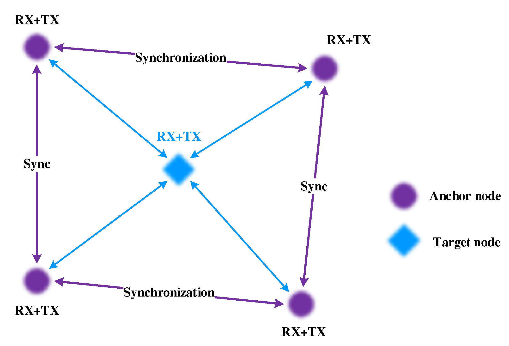
11]. Among these parameters, the TDOA is one of the commonly used method that has the advantages of high measurement accuracy, simultaneous removal synchronization of nodes and easy implementation and operation. In the ranging-based localization, the signal distance from the target node to the anchor nodes can be used to estimate the internode distances together with the propagation speed or the channel fading model. And then, a target node can be located by a set of anchor nodes that measure the time difference, as shown in
Figure 1 [
12]. The difficulty of TDOA method is to estimate the distance between nodes, especially in dynamic and industrial environments. In these environments, most narrowband signals are highly attenuated, resulting in a decrease in the ranging accuracy.
Some recent studies have shown that the placement of more anchor nodes, increased node signal transmission power [
8] and enhanced cooperation between nodes can improve the accuracy of localization [
9,
10,
11]. However, in the context of IoT, some devices have stringent energy requirements and computational requirements. Under the premise of ensuring localization accuracy, how to reduce energy consumption and extend network life to meet the localization and deployment requirements are challenges [
13]. Indoor localization is gaining increasing attention and various technologies have been applied to localization including Wi-Fi, Bluetooth, radio frequency identification (RFID), acoustic signals, magnetic fields, UWB and light. Among them, due to the high ranging accuracy (<10 cm) of UWB becomes an excellent technique for precise localization. Compared with narrowband signals, UWB signals have an advantage in precise localization due to their high temporal resolution and potential for multipath resolution. However, the localization schemes commonly used with UWB have their own limitations. Due to the limited transmission distance of UWB signals, localization in multi-area network during the movement process are particularly important. In addition, the ranging and localization of fixed positions are relatively simple and the localization accuracy can be improved by continuously optimizing the error. However, localization the moving node requires not only the frequency of the localization but also requiring the transmission power of the signal, the collision loss rate and so on.
For mobile nodes, which are generally powered by batteries, resources are limited. The lifetime of location-aware network will affect the survival of the localization system. Therefore, a location-aware network requires lower power consumption [
14,
15,
16]. The IEEE 802.15.4a standard [
17], which defines several deterministic channel access schemes, is a valuable candidate for communication requirement systems in low-power-consumption networks. The standard imposes certain physical layer (PHY) guidelines, such as the transmission power. With the increasing number of anchor nodes, the reliability of localization becomes limited, as interfering messages may interrupt the required message exchange. Moreover, the localization system needs to consider the impact of the medium access control (MAC) layer protocol within practical implementations. A carrier sense multiple access (CSMA-CA), offer good benefits relating to changes within the network but are not suitable for UWB-based location-aware networks with a large of nodes due to the listen-before-talk mechanism, which requires sensing the medium. To overcome the limitations of existing approaches, the time division multiple access (TDMA) MAC approaches are more beneficial for high user densities in the location-aware network than contention-based approaches [
18]. Therefore, providing satisfactory localization availability in the mobile localization process is one of the main challenges that has yet to be solved.
In a location-aware network, due to the limitation of wireless resources, only a limited number of node pairs can perform measurements between nodes simultaneously. To effectively utilize limited wireless resources (such as bandwidth) to located more nodes, the design of a targeted network transmission strategy is essential. Network transmission strategies affect location reliability. Song [
19] developed a framework for evaluating metric network transmission strategies and proposed a context-aware network transmission strategy method to mitigate network localization errors. Garcia [
5] established an optimization framework for a joint localization network with the goal to allocate STDMA network resources and perform UWB TW-TOA ranging. In these two localization systems, there is no system analysis of other localization aspects, such as large area coverage, tag roaming or multiuser interference, which are critical to achieving real-world indoor deployment. For example, in [
14], the authors compared two existing solutions in terms of the accuracy, location update rate and end-to-end latency. In addition, the combination of TDMA and other methods, such as code division multiple access (CDMA), was studied in [
9]. Although the MAC was analyzed in terms of delay, it was not shown whether this method can further improve scalability to support higher user density. In such a context, designing an effective and efficient UWB localization system is very challenging in industrial communications [
20].
In this paper, we focus on the IEEE 802.15.4a standard to enable the adoption of the low-latency deterministic network (LLDN) mode as the basis for UWB location-aware networks. Furthermore, we consider the lifetime of targets with low-rate, low-power networks and the number of nodes. We present RMLNet, an efficient network addressed on the MAC layer, which guarantees the general localization application reliability on different UWB network zones. Specifically, we present how to support localization by applying slotted scheduling. The design requires specific and optimized solutions for managing and coordinating multiple anchor nodes. In addition, an approach of target area determination is proposed, which can approximately determine the region of the target node by RSSI, to support RMLNet. Furthermore, we design the system to estimate the multi-area localization of the target node and evaluate its performance. Experiments show that RMLNet can achieve localization application reliability in multi-area localization with a better accuracy of competing target nodes.
The rest of this paper is organized as follows. In
Section 2, we review the studies on UWB localization networks related to our work.
Section 3 describes and analyzes the overview of the TDOA-based localization system. Then,
Section 4 discusses the proposed mechanism, including the proposed target area determination approach and network scheduling mechanism. The performance of our prototype network is analyzed in
Section 5. Finally, the conclusions are drawn in
Section 6.
4. System Design
This paper presents a UWB indoor localization system using a TDOA localization approach that ensure collision-free access to the network. The design requires specific and optimized solutions for managing and coordinating multiple anchor nodes. The design of a specific solution related to target area determination, anchor node slot allocation, target node intervention and movement can impact the realization of the network and the system, which is presented in this section.
4.1. Process of Localization
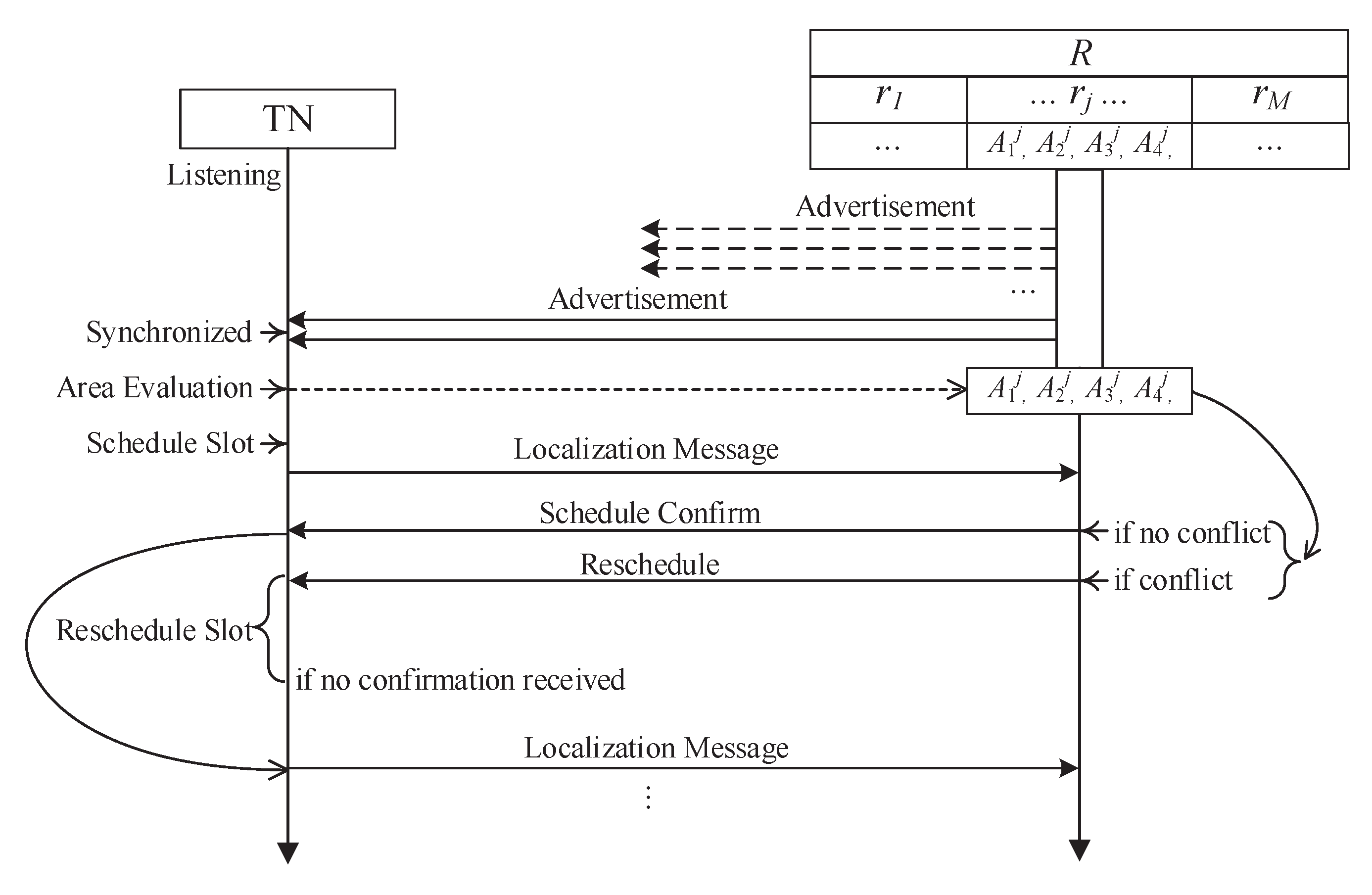
The network process between the target node and anchor nodes of the localization system described in this design is shown in
Figure 4. The process is as follows:
The anchor node broadcasts a synchronization and localization signal in the public frequency band andthe target node receives it. The anchor and target complete synchronization and determine the target node region using the signal strength.
The target node sends localization signals, including the region information, in the regional frequency band according to the regional slot scheduling strategy.
According to the regional slot scheduling policy, the target node randomly selects the free slot in the current region and sends access requests in the access slot. If the target node does not receive the slot allocation policy in the next slot, this node considers the access request to have failed and reselects the free slot to send the access request again. The anchor node broadcasts the timeslot scheduling strategy in the regional frequency band. The target node adjusts the receiving frequency band and receives the timeslot scheduling strategy.
In the process, the phase of synchronization, area determination and timeslot schedule of the anchor node is in the broadcast state and the transmission and node access phase are in the listening state. Correspondingly, the target node has three phases in the listening state and two phases in the receiving state. The functions of each phase are described below:
4.2. Target Access
The target node moves to a new region but it does not immediately know its position, so it can determine only its access time by receiving broadcast information from the anchor node. There are two types of target node access—node startup and node movement across regions.
Node startup—The target node is in the listening state and receives the broadcast signal from the anchor node. After completing the phases of synchronization and area determination, the target node adjusts the listening frequency to receive the scheduling signal from the anchor node in its region. The scheduling signal includes information such as the number of all target nodes in the current region and the slot allocation strategy.
Node cross-region—The target node uses the RSSI to determine whether the cross-region is completed. If it is not completed, the transmission of localization signals is carried out according to the slot allocation strategy of the previous region. After the target node completes the cross-region movement, the target node adjusts the listening state, receives the synchronization information, localization information and scheduling information from the anchor node of the new region and randomly selects the free transmission slot in the access slot of the new region to send the access request.
That is if the target moves within the original area, it will transmit the localization signal according to the slot allocation strategy at the previous moment. If the target node moves cross-region, the target node adjusts the listening state, receives the synchronization information, localization information and scheduling information from the anchor node of the new region and randomly selects the free transmission slot in the access slot of the new region to send the access request. Note that the target node receives the slot allocation strategy in the scheduling time slot. If the target node does not receive the slot allocation information, it sends an access request in the stage of node access. We stipulate that if the anchor node does not receive the localization signal from the target node for more than three frames, which indicates that the target node has left the area or has been closed, the anchor node releases the time slot occupied by the target point in the next frame.
4.3. Target Area Determination
In
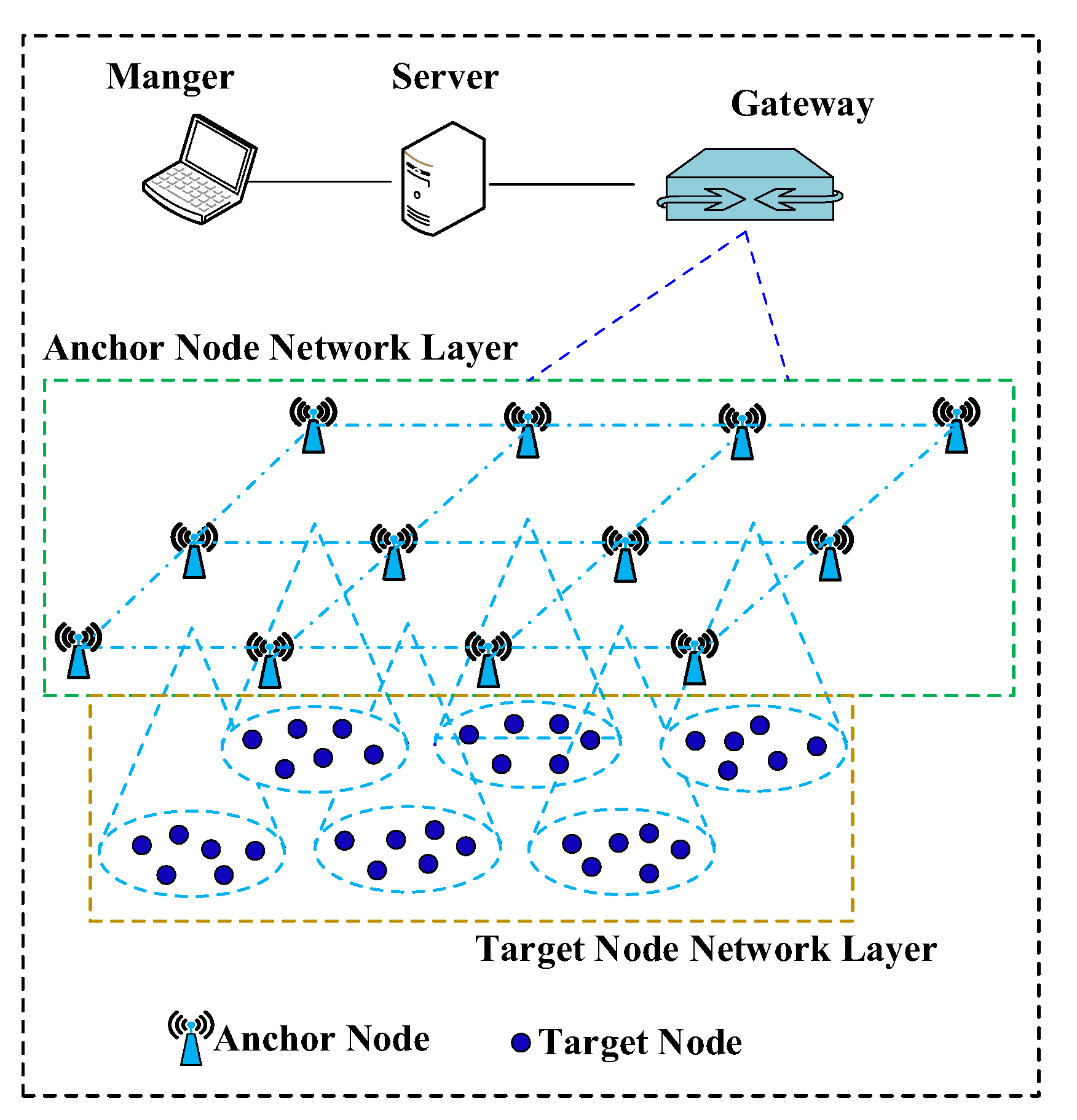
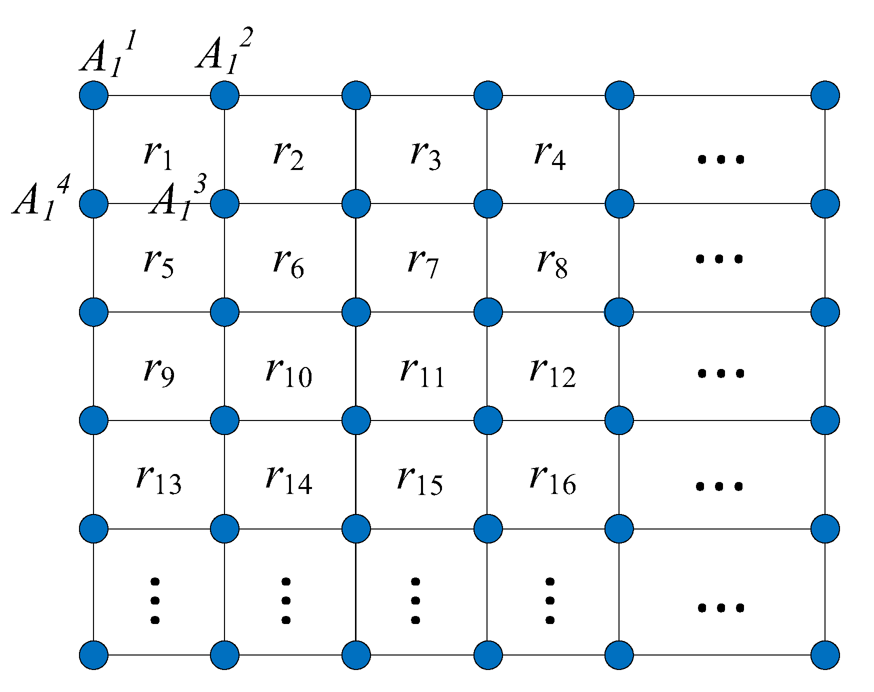
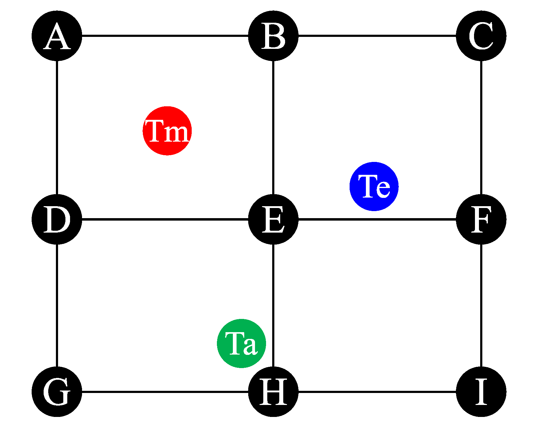
Figure 3, the target node receives the signal from anchor nodes in different cell regions and records the RSSI. In general,
RSSI is proportional to
, where
d is the propagation distance between the target node and the anchor node and
is the path-loss exponent. The relation between the RSSI and the propagation distance can be represented as
and a simplified model is given by the following:
where
A is Gaussian additive noise with zero mean and standard deviation
related to the specific connections.
To further describe the relationship between the RSSI measured by the target node from
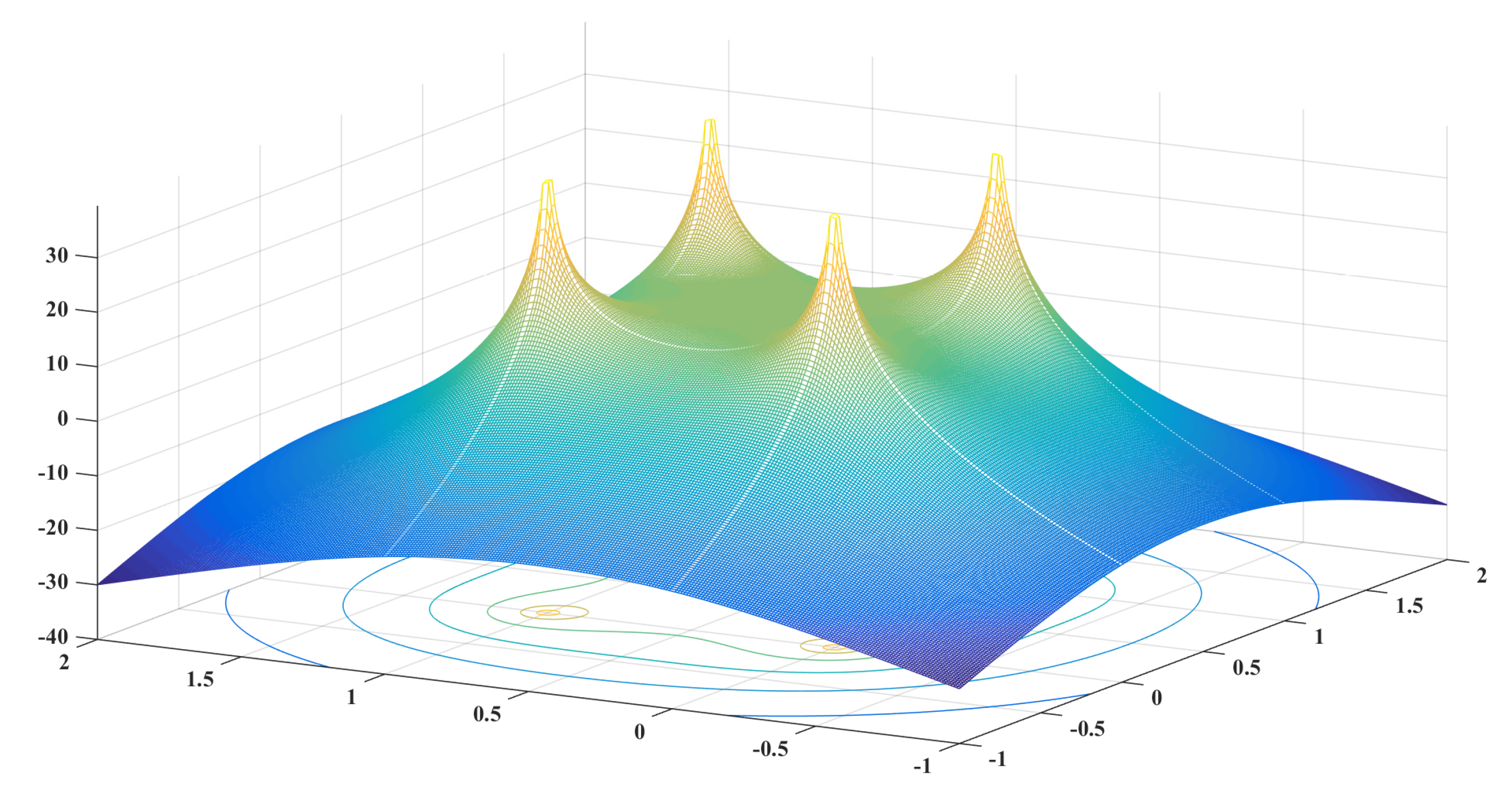
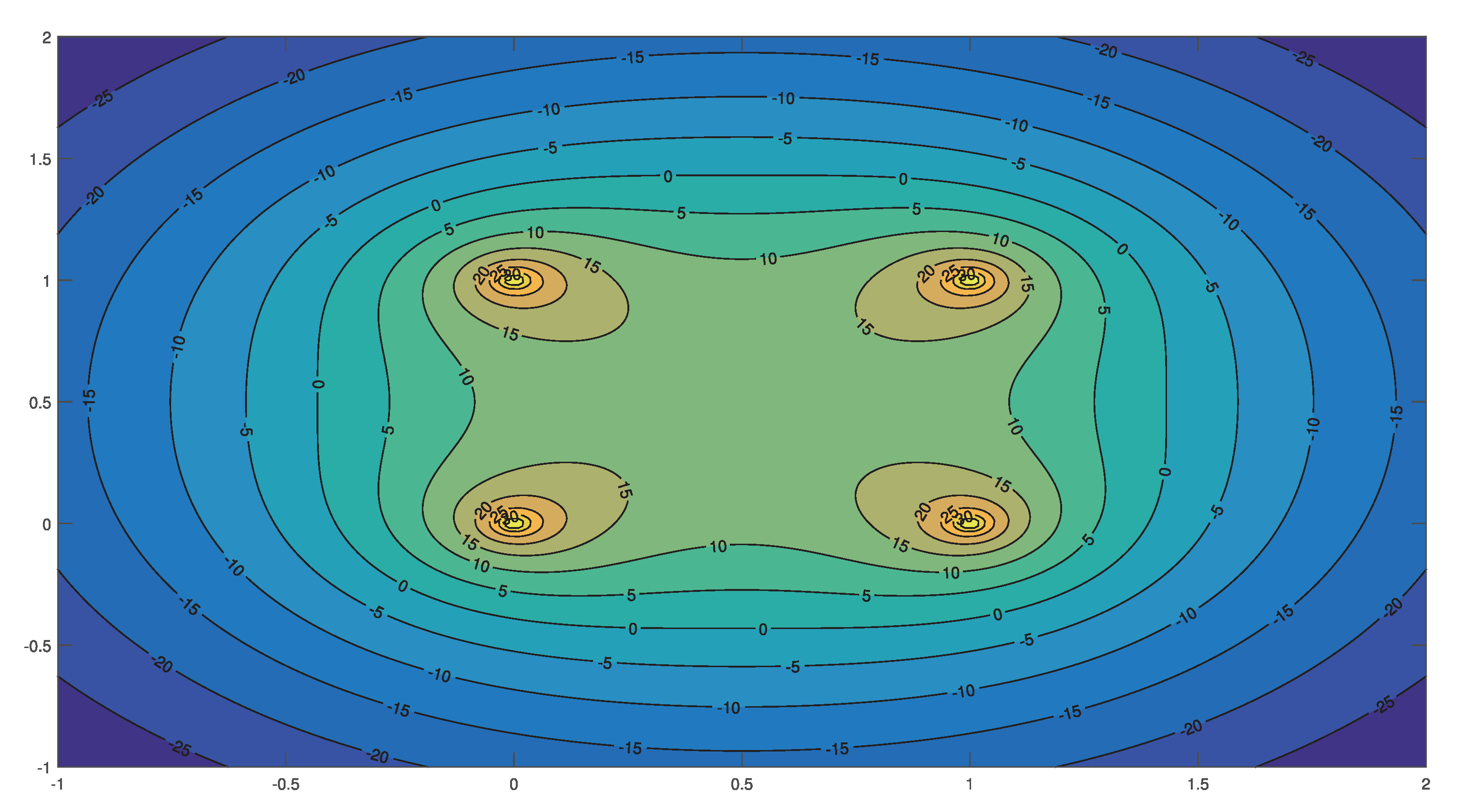
and the position of the target node, we tested the performance of the RSSI in a region under ideal conditions. The coordinates of anchor nodes were
. The results are shown in
Figure 5 and
Figure 6. So, in theory, the RSSI received by the target node in the region is greater than that received outside the region. Therefore, we can approximately determine the region where the target node is located by comparing the the RSSI values in different regions. We define
as the region of the target to be determined, such that
where
represents the RSSI value of an advertisement broadcasted by
, and
represents the sum RSSI of node the
n in region
. According to Equation (3),
We can approximately determine the region of the target node by Equation (4). The region with the maximum is the region where the node is located.
Figure 5 and
Figure 6 show that
is generally larger near the anchor node in region
. Theoretically, the RSSI has an extreme value in the region far from the anchor node and a maximum value at the regional center. The RSSI decreases along the regional center to the midpoint direction of the anchor nodes and reaches the minimum value at the midpoint. Thus,
Theorem 1. If there is a maximum value of the RSSI at the regional center, then the minimum value of the RSSI within the region is at the midpoint of the regional boundary.
Thus, there is a minimum value of the RSSI in the region near the midpoint of the anchor nodes. All values in this region should be greater than the minimum value. Thus, we can introduce a threshold determination mechanism to locate the region of the target node more accurately. As mentioned above,
is mainly affected by the nearby anchor node and changes little near the boundary of the region, which affects the region determination of the target node. We introduce
, the minimum value of the RSSI in the region as the threshold determination to assist in locating the region of the target node.
where
represents the minimum value of the RSSI in the region
.
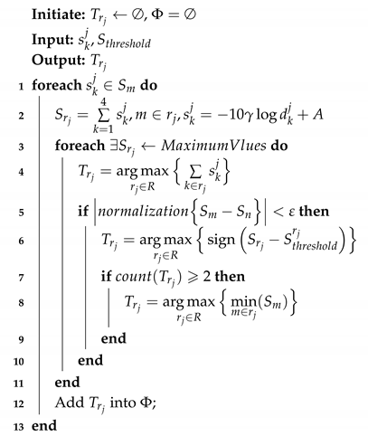
We can approximately determine the region of the target node by Equation (6), as the target node communicates near the boundary of the region. However, due to signal transmission errors, multiple values close to each other can be obtained by Equation (6). At this point, the region where the target node is located needs to be further determined.
The region where the target node is located depends on the anchor node, which is farthest from the target node among the four anchor points constituting the region. For cases where multiple values are similar, we can calculate the minimum of
in each region and then obtain the maximum value of these minimum values.
represents a collection of RSSI values measured by the target node in all regions.
The region containing the anchor node with the largest RSSI is the region containing the target node. Therefore, we can determine the region of the target node by Equation (7) when there are multiple values close to each other as obtained by Equation (6).
Thus, we can determine the region of the target node by Algorithm 1.
| Algorithm 1: Determine the region |
![Sensors 19 04374 i001 Sensors 19 04374 i001]() |
4.4. Slot Scheduling
The ANNL adopts the TDMA MAC protocol for all communication. We give the communication resources scheduling in this subsection according to the scenario displayed in
Figure 3 and the overview. The process of localization is demonstrated in
Figure 4. First, when a target node first moves into a new target area, the node needs to be synchronized by the advertisements broadcast by the anchor nodes. Through such advertisements, the target node can evaluate its area and preschedule the timeslot for the transmission of localization messages. Second, the target node should send the localization-related information to anchor nodes after synchronization. Then, the anchor nodes send the scheduling information to the target nodes. The scheduling is confirmed when the target node received confirmation. A conflict may occur when more than two target nodes move into the same target area at the same time. Thus, we schedule the final step downstream to avoid the resource conflicts and improve the reliability of communication resource scheduling.
Several repeated timeslots construct a superframe. As shown in
Figure 7, we divide a superframe into three segments—the broadcast timeslot segment (BTS), the target timeslot segment (TTS) and the scheduling timeslot segment (STS). In the design, a superframe contains of 500 timeslots, each of the timeslot is 20 ms. The setting of the timeslot mainly considers two factors—the transmission rate of the radio chip and the time during the server calculates the localization result. First, the transmission rate of data packets in the RF chip is 6.8 Mbps and the size of each packet is 127 Bytes. In theory, the time it takes to send a packet is 0.15 ms. Second, the server to solve a set of coordinate values using the TDOA algorithm is less than 10 ms.
In the BTS, each anchor node broadcasts in its own area. The advertisement packet contains the timeslot bit table. That is, each anchor node announces the current timeslot scheduling in its own area among TTSs. The designed format of the advertisement packet is shown in
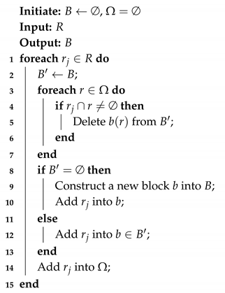
Figure 8. The advertisement packet contains an IEEE 802.15.4 MAC header, network header and payload. We use the payload mainly to tell the target node the current usage of timeslots. The payload consists of the number of areas (AN) and the serial number of areas and their bit table. One of the bits in the bit table, ‘0,’ represents unscheduled timeslots in a block and‘1’ represents scheduled timeslots. Each bit table represents one block of timeslots in the TTS. Once the target node receives the advertisement packets, it disassembles the area and bit table. According to the area self-evaluated in Algorithm 1, the target randomly chooses an idle timeslot in the corresponding bit table as its upstream timeslot in the TTS.
The TTSs supply localized information of the target node. Since the target areas are different, each area needs a block of timeslots. To save resources, different areas can reuse the same timeslots. Thus, we design Algorithm 2 to generate a block of timeslots. represents the temporary collection for storing the scheduled area and is a collection of timeslot blocks. We adopt the graph coloring algorithm to solve the allocation of upstream timeslots. Each block contains several timeslots to support the target node in an area. The number of timeslots of a block depends on the maximum number of target nodes in an area. The adjacent area cannot use the same block because that condition would result in wireless interference and the sharing of same two anchor nodes. However, different areas can use the same block if they do not share the same anchor nodes. Based on our experience, we assume that no wireless interference occurs if the areas are not adjacent.
| Algorithm 2: Schedule |
![Sensors 19 04374 i002 Sensors 19 04374 i002]() |
The STSs are used downstream for scheduling information. In a block, a timeslot can be used for one target node only. Thus, if more than one target node selects the same timeslot in the same area, a conflict may arise. When the anchor nodes receive the localization packet of a target node, they send the scheduled information to the target node in the corresponding timeslot. This packet is multicast. Thus, when the other target nodes receive the packet, they will find that they are not scheduled. Thus, they will reselect the upstream timeslot in the next superframe. Each area selects a major anchor node to send this scheduling information.
5. Implementation and Experiments
In this section, we first introduce the system based on RMLNet and then evaluate the performance of the stability and accuracy of the RMLNet-based localization system.
5.1. System Implementation
To evaluate our proposed RMLNet, we designed a system based on UWB, which can overhear signals and mark the recorded messages with a timestamp. We used the DecaWave DW1000 as radio transceivers, which is compliant with the IEEE 802.15.4-2011 standard. The controlling framework of transmitting or receiving the timestamp was actualized by an STM32F105 chip with Contex-M3. We integrated these nodes into the RMLNet network.
In this system, target nodes are arbitrarily deployed in the sensing field and each node has the same transmission range and similar hardware configurations. The whole sensing field is partitioned into grids. As discussed in the previous sections, the RSSI is utilized to localize the area of the target nodes first. Then, the target node sends localization signals in the regional according to the regional slot scheduling strategy. We measure the TDOA by ASync-TDOA [
12]—a model for TDOA localization without time synchronization—which achieves the time difference in a one-way-based range by introducing the reference node. After calculating the TDOA, the localization of the target node is estimated by the optimization algorithm.
5.2. Experimental Scenario
We performed extensive experiments to examine the feasibility of ASync-TDOA for localization in a large-scale wireless network. As shown in
Figure 9, we used a laboratory to simulate the factory environment. For simplicity, we considered a 2D localization model to compare with other models. We measured the time difference and estimated the localization in this environment to evaluate the proposed model.
The coordinates of anchor nodes are , , , , , , , and . We defined three target scenes—near the middle , near the anchor node and near the edge of a line between two anchors . In all experiments, the target node is static and transmits a packet every 200 ms. The localization of each setting was conducted many times.
5.3. Target Area Determination
This test mainly evaluated the performance of the target area determination. As shown in
Figure 9, 4 target nodes are placed in each scene at
,
and
, and each test is conducted 1000 times.
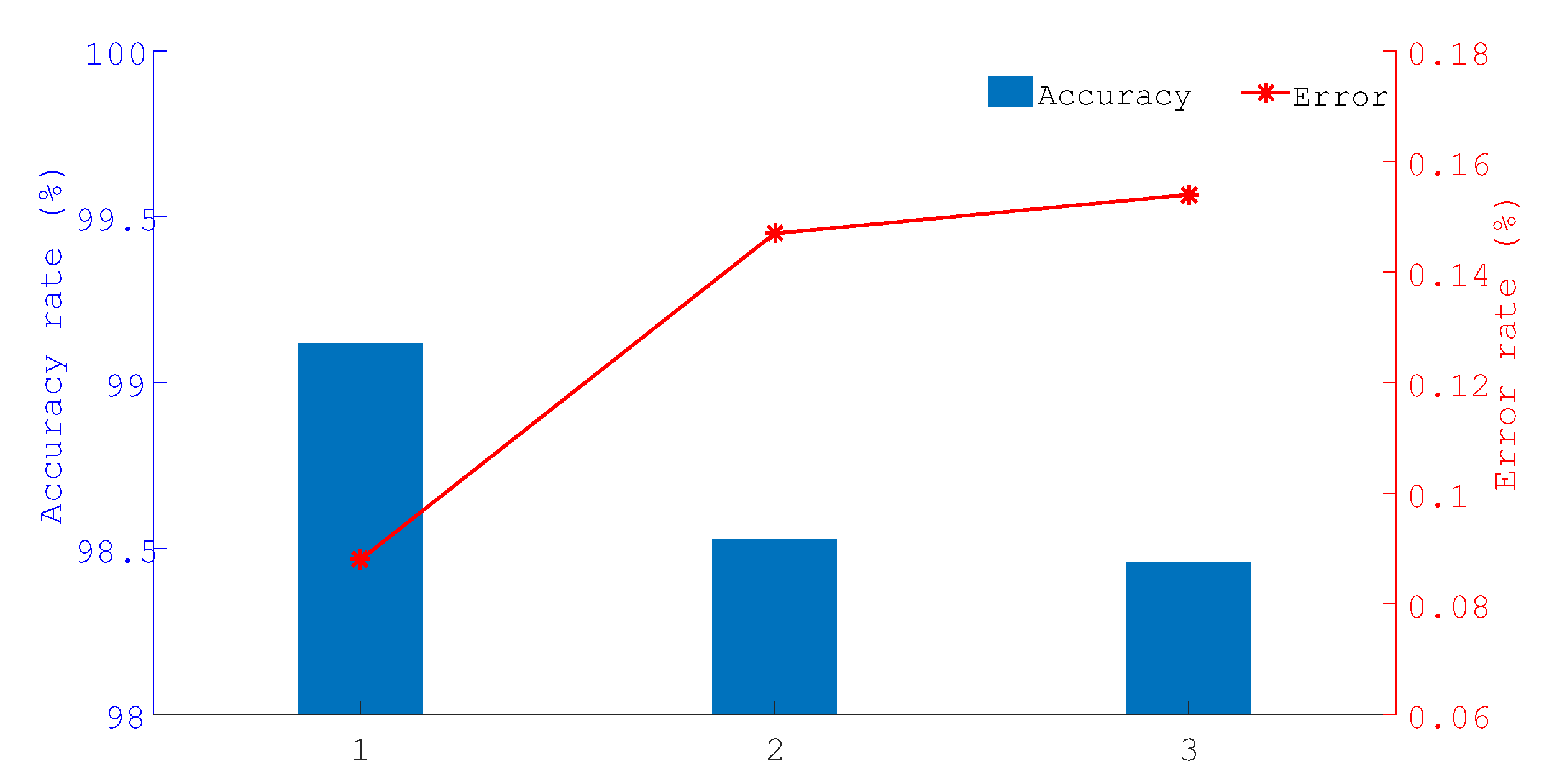
Figure 10 shows the percentage ratio of the correct times to the test times. Here, ‘1’ represents the scene of the target being near the middle ‘2’ represents the scene of the target being near the anchor node and‘3’ represents the scene of the target being near the edge of a line between two anchors. As shown in
Figure 10, the proposed project of the determine region has a better success rate, which can exceed 98.5% and guarantee the performance of the network for multi-area localization.
5.4. Localization Performance
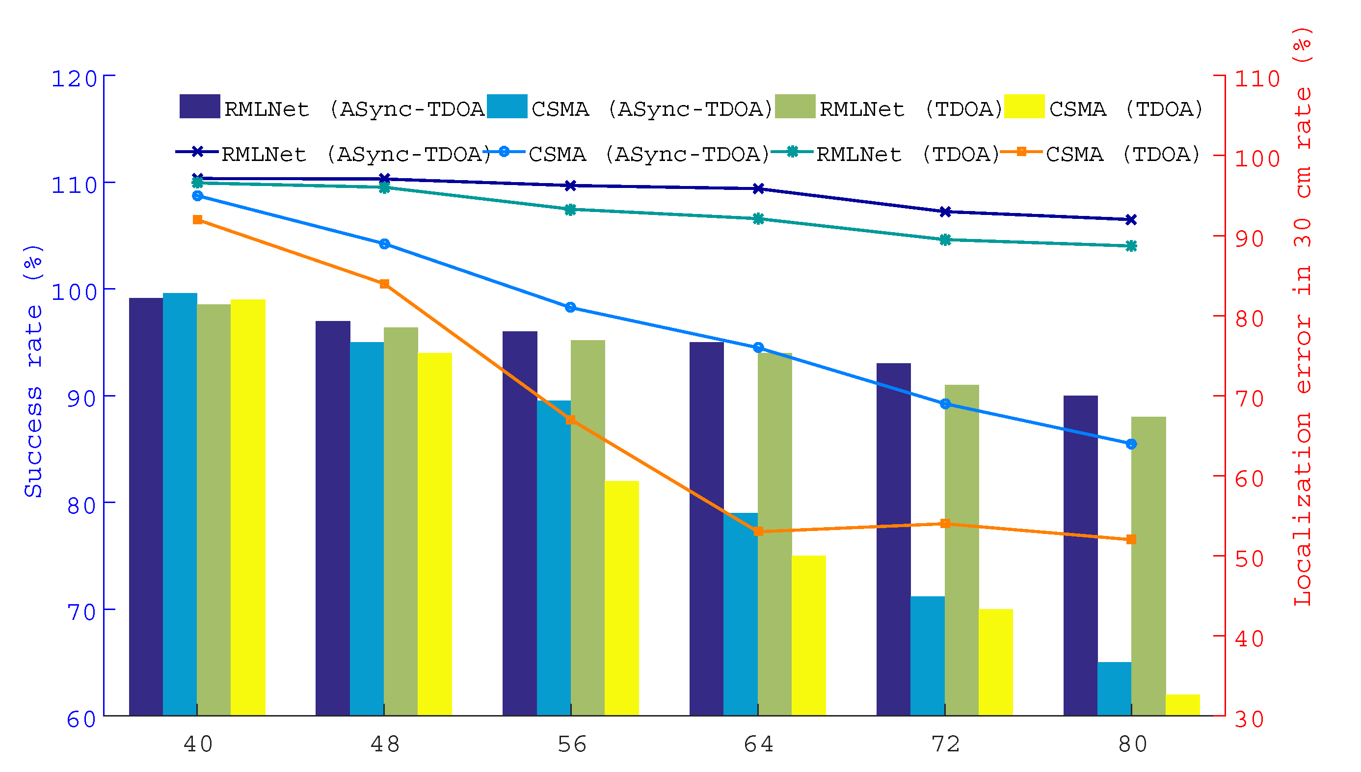
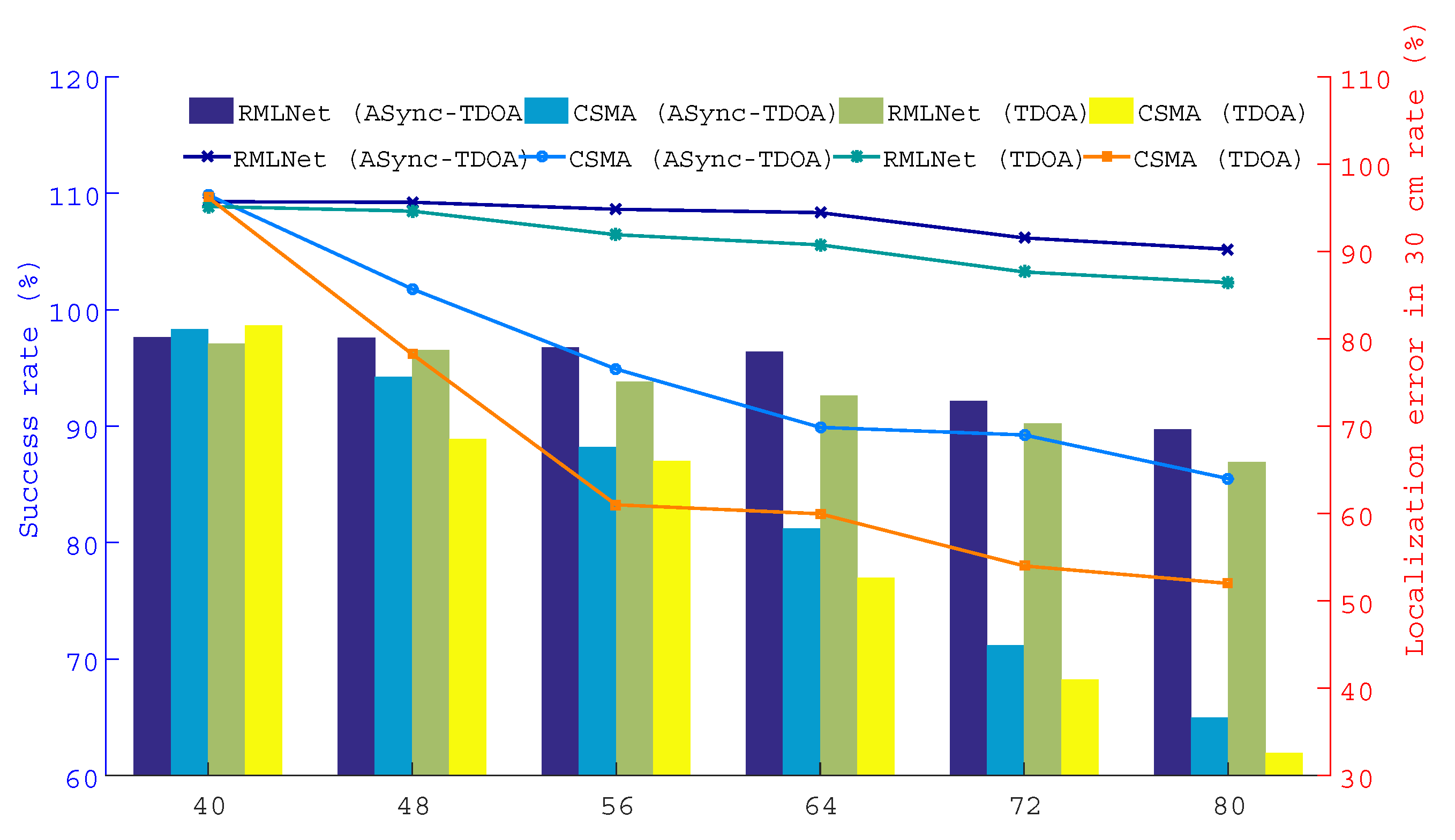
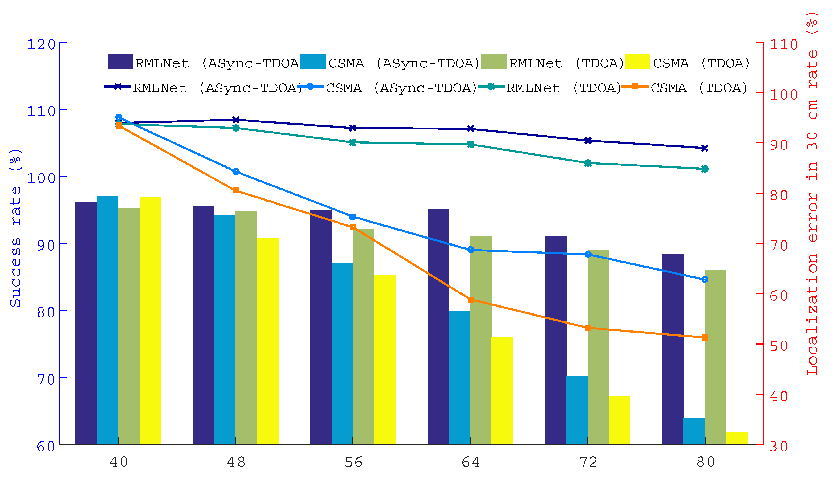
This test compares the performance of the localization in the RMLNet network and CSMA network with the results for the ASync-TDOA and traditional TDOA, respectively. As shown in
Figure 9, 12/14/16/18/20 nodes are placed in each region and a total of 48/56/64/72/80 nodes are placed in each scene.
The results are shown in
Figure 11,
Figure 12 and
Figure 13, which show the successful localization of the RMLNet network and CSMA network based on the ASync-TDOA or traditional TDOA and the percentage of successful localization errors within the range of 30 cm. The bar graph represents the percentage of successful localization events versus the total test number, while the broken line graph represents the percentage of localization errors within the range of 30 cm.
Figure 11 shows the results for the target nodes being near the center,
Figure 12 shows the results for the target nodes being near the anchor point and
Figure 13 shows the results for the target nodes being near the boundary. We can see that the location effect of the RMLNet network is better than that of the CSMA network using two TDOA methods.
There are 40 target nodes for localization, the location results of the RMLNet-based localization are worse than those of the CSMA-based localization. The reason is that few target nodes and less competition in the CSMA network, that will not cause data conflicts. However, the process of localization in the RMLNet network needs to execute regional evaluations, which may fail and affect the performance of localization. At this time, the interference that affect the wireless transmission mainly comes from the NLOS and the electromagnetic operation of the device, which may cause the link transmission to fail. And the success rate of the localization cannot reach 100%. With the increases of the number of target nodes, the success rate of localization based on both networks are decreased. But the performance of RMLNet-based localization is still better than that of CSMA-based. The reason is that when target nodes are located in the same area, the more target nodes there are, the more likely transmission collisions are. The transmission of CSMA-based network is based on the competition mechanism, which decreases the success rate of the localization. The RMLNet network has designed a time slot allocation strategy, which basically guarantees the reliability of localization information transmission. However, due to interference between more target nodes, the success rate of localization will be decreased.
Furthermore, the probability of error of the RMLNet-based localization at 30 cm is greater than that of CSMA-based. With additional nodes, the localization performance based on the CSMA network is worse than that of the RMLNet network because the RMLNet network localization process does not conflict and because the success rate of localization is high. For the same localization model, the data acquired by the network with good performance has high reliability, which leads to more localization events. Moreover, the stable network performance lays a foundation for the accurate measurement of data.
In addition, as shown in the
Figure 11,
Figure 12 and
Figure 13, ASync-TDOA localization performs better in both networks than traditional TDOA localization, especially in CSMA-based networks. The reason is that the ASync-TDOA location does not require time synchronization and involves less communication between nodes. The traditional TDOA can be located only after synchronization but the synchronization results affect the localization. As synchronization fails, the success rate of localization is affected.
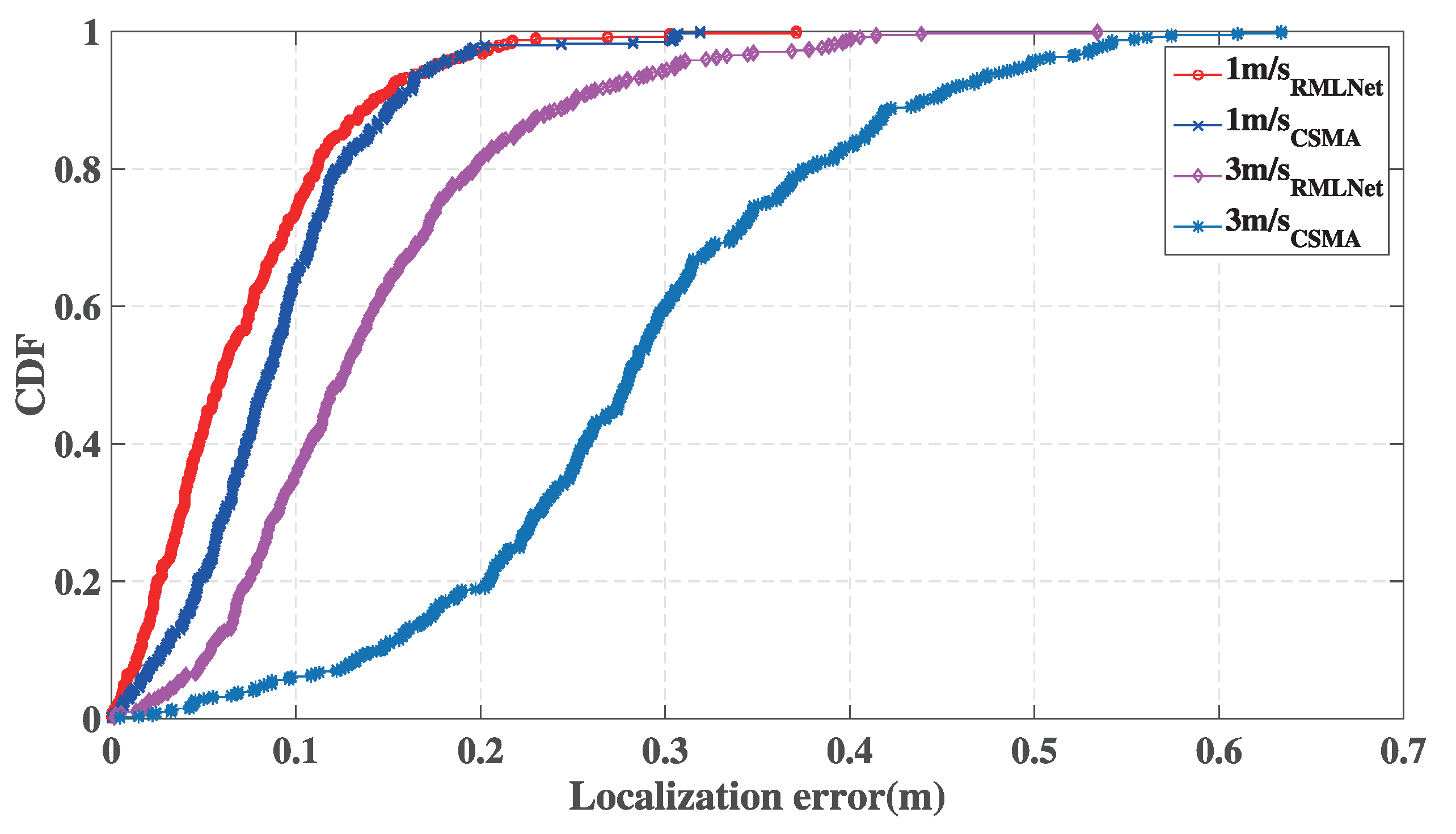
Figure 14 shows the localization performance at different speeds. We set 10 target nodes to move randomly for 10 min at different speeds in the scene shown in
Figure 9 at 1 m/s and 3 m/s. The CDF of the statistical localization error of the test node in different networks is calculated by the ASync-TDOA [
12].
Overall, the performance of the RMLNet-based localization is better than CSMA-based localization. With the increase of the moving speed, the error of the localization increases. The reason is that the nodes in the network are waiting for a response will take some time and the localization will change during that time. When the speed of the target node is slowly, the node moves at a small distance or does not move and the performance of the network can ensure that nodes obtain comparatively accurate information for localization. Increasing the speed, the localization of the target node changes rapidly, which causes the measured localization information are changing and the error of localization is increasing. When the target node moves at 1 m/s, the localization error of the RMLNet-based localization is within 0.3 m for 99% and that of CSMA-based localization is within 0.3 m for 98.6%. When the target node moves at 3 m/s, the localization error of the RMLNet-based localization is within 0.4 m, while that of the CSMA-based localization is within 0.65 m. The RMLNet network reduces collisions and ensures the reliability of each localization. During the process of the cross-region, the location information of the node is obtained with a large error or missing andthe localization error is increasing or cannot be located. The localization based on the RMLNet network incorporates a mechanism of target area determination, which restricts the target nodes in the area. Use of the RMLNet network improves the success rate and accuracy of localization.
Figure 15 shows the location trajectory of two target nodes in different networks. We can see that the update rate of the target node will make a difference results in TDOA localization. For the CSMA-based localization, when the update rate of the target node is 1 HZ, the target will occasionally be lost and drifted. When the update rate of the target node is 5 HZ, the trajectory will have obvious discontinuities and the target cannot be located. For the RMLNet-based localization, when the update rate of the target node is 1 HZ, the location trajectory of two target nodes are stability. When the update rate of the target node is 5 HZ, the target will occasionally be lost and drifted. The reason is that the increase of the update rate will inevitably increase the communication load and the probability of collision of the data packet increases. If there is a collision between data transmissions, high-reliability channel access cannot be ensured by CSMA-based network, which is based on the competition mechanism. The RMLNet network has designed a time slot allocation strategy, which basically guarantees the reliability of localization information transmission. However, due to the interference of target nodes, the location trajectory of two target nodes will occasionally be lost and drifted.
Based on the above results, we can conclude that, first, the region of the target node can be approximately determined by the proposed RMLNet. Second, during the switching of the localization area in the movement process, RMLNet achieves reliable localization on multi-area with a better accuracy and stability of competing target nodes.
