Design and Implementation of Arch Function for Adaptive Multi-Finger Prosthetic Hand

 and
and 
Abstract
:1. Introduction
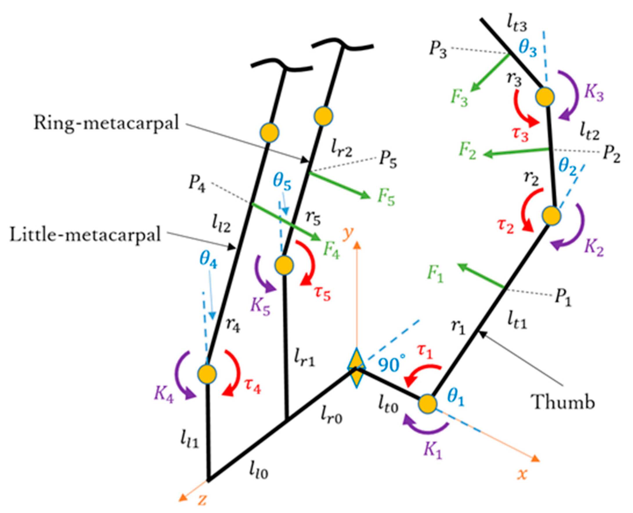
2. Digit Design
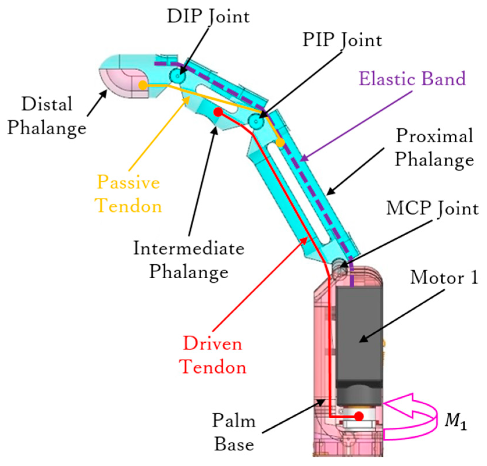
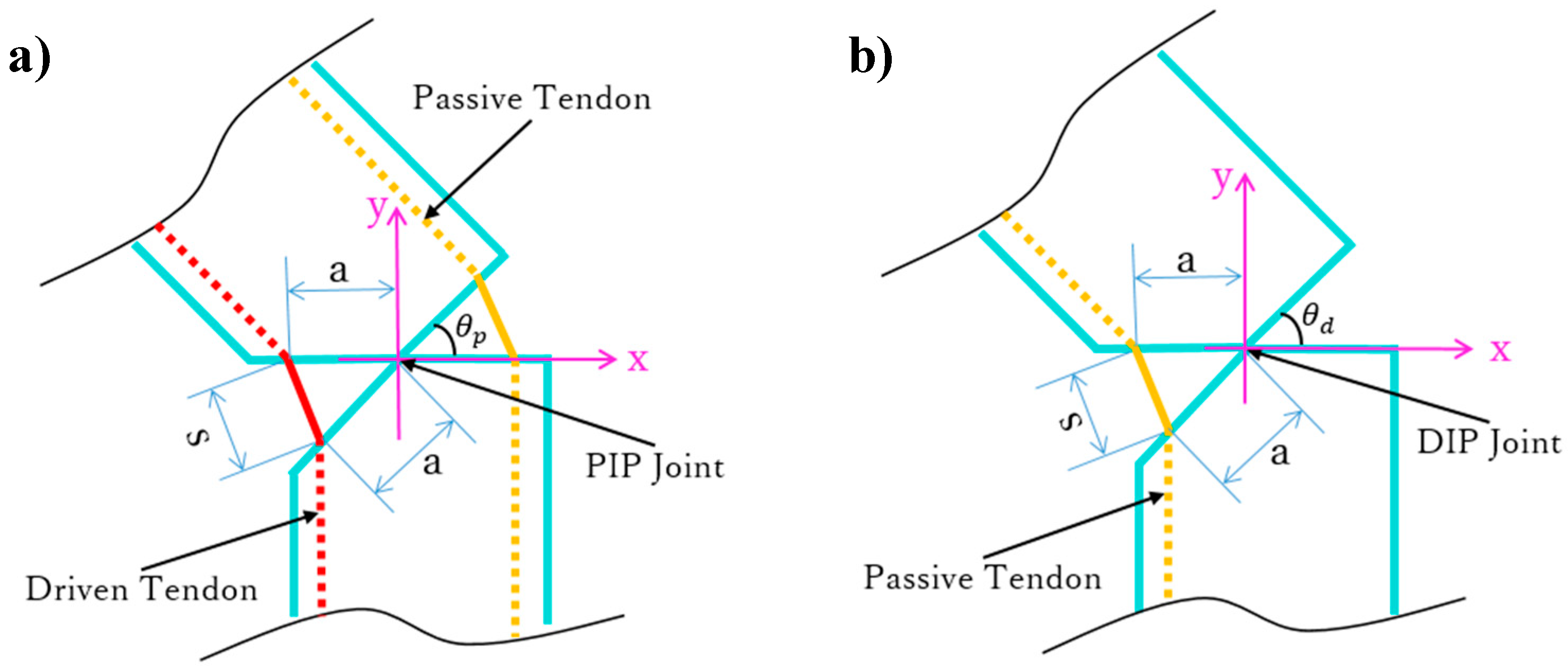
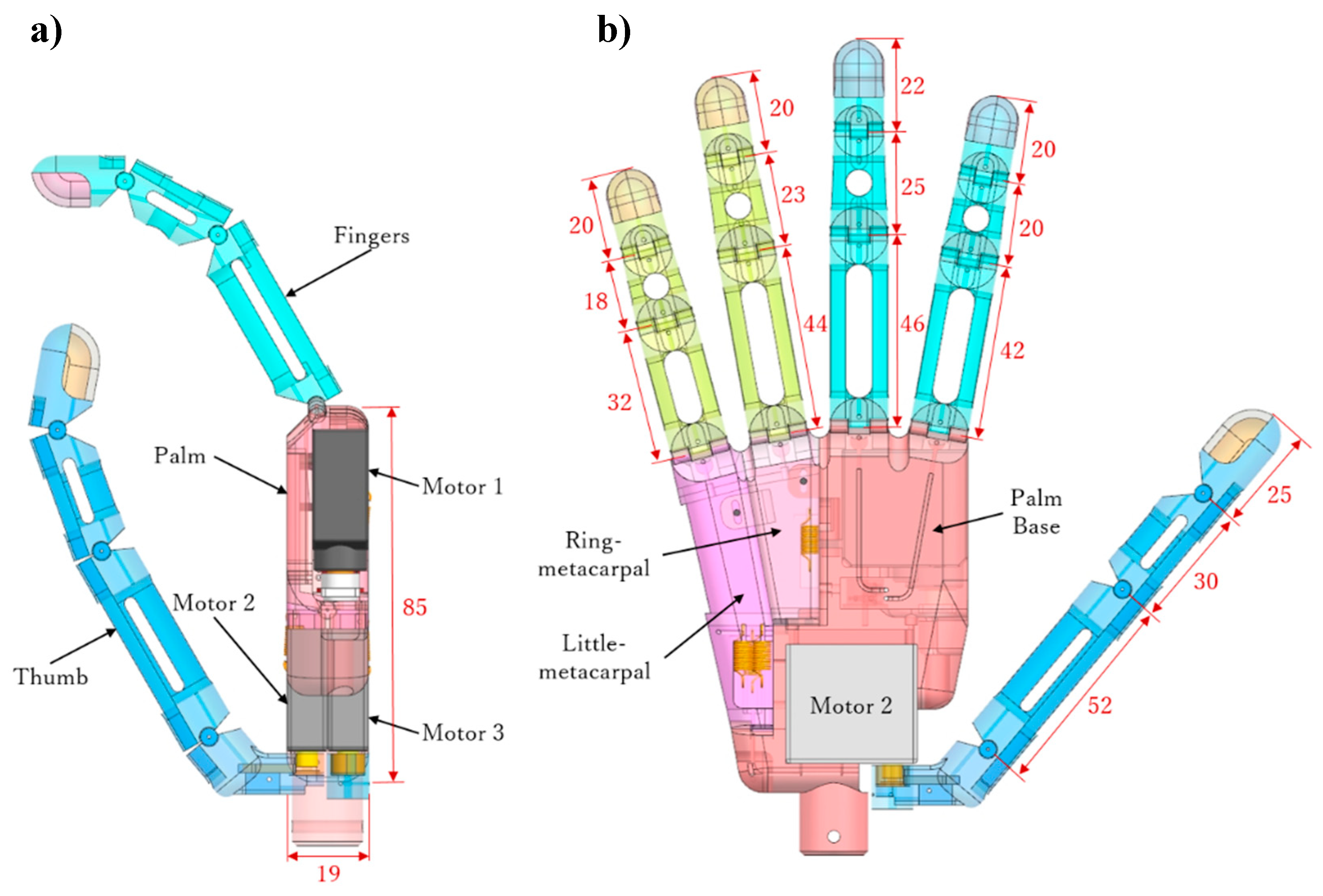
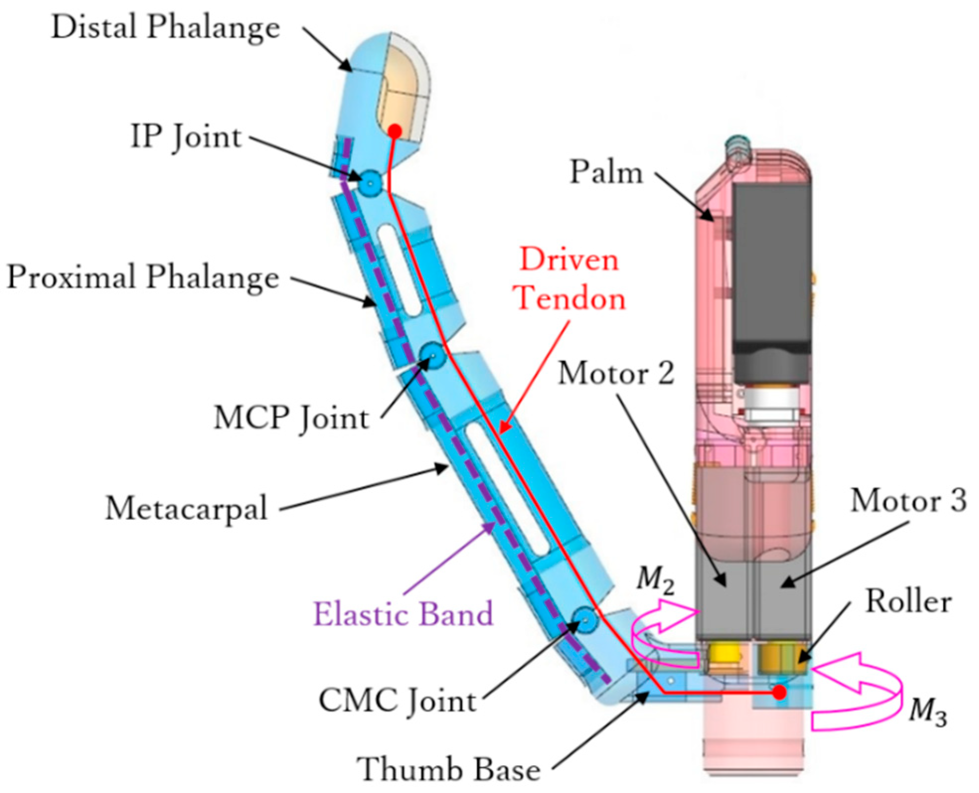
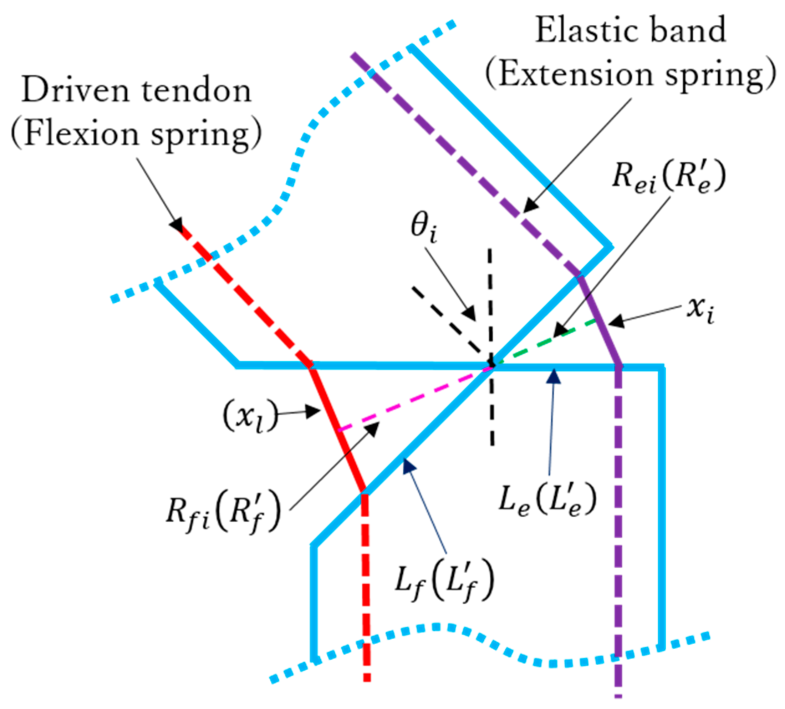
2.1. Fingers
2.2. Thumb
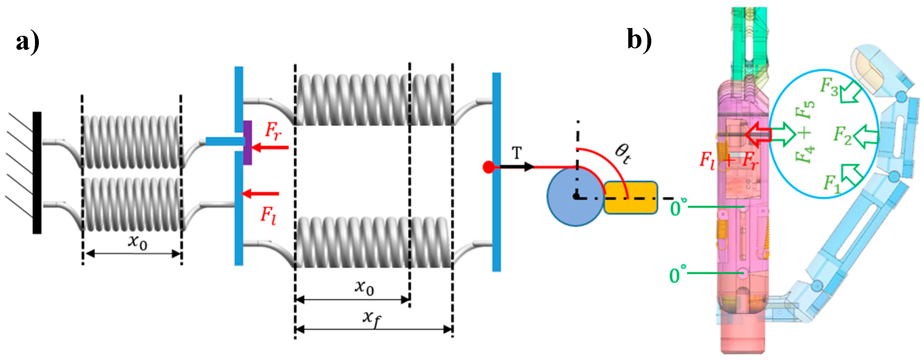
3. Arch Function
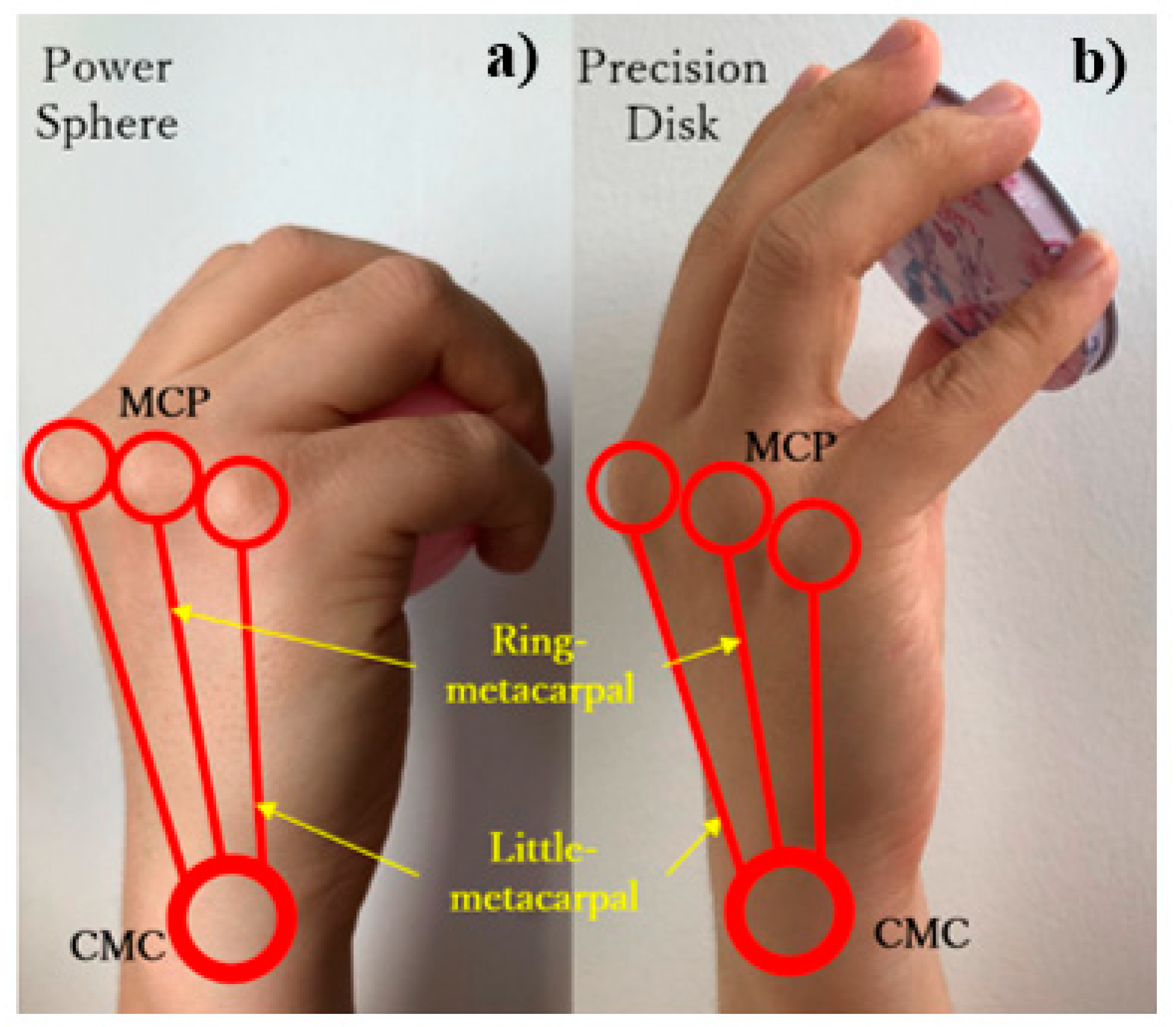
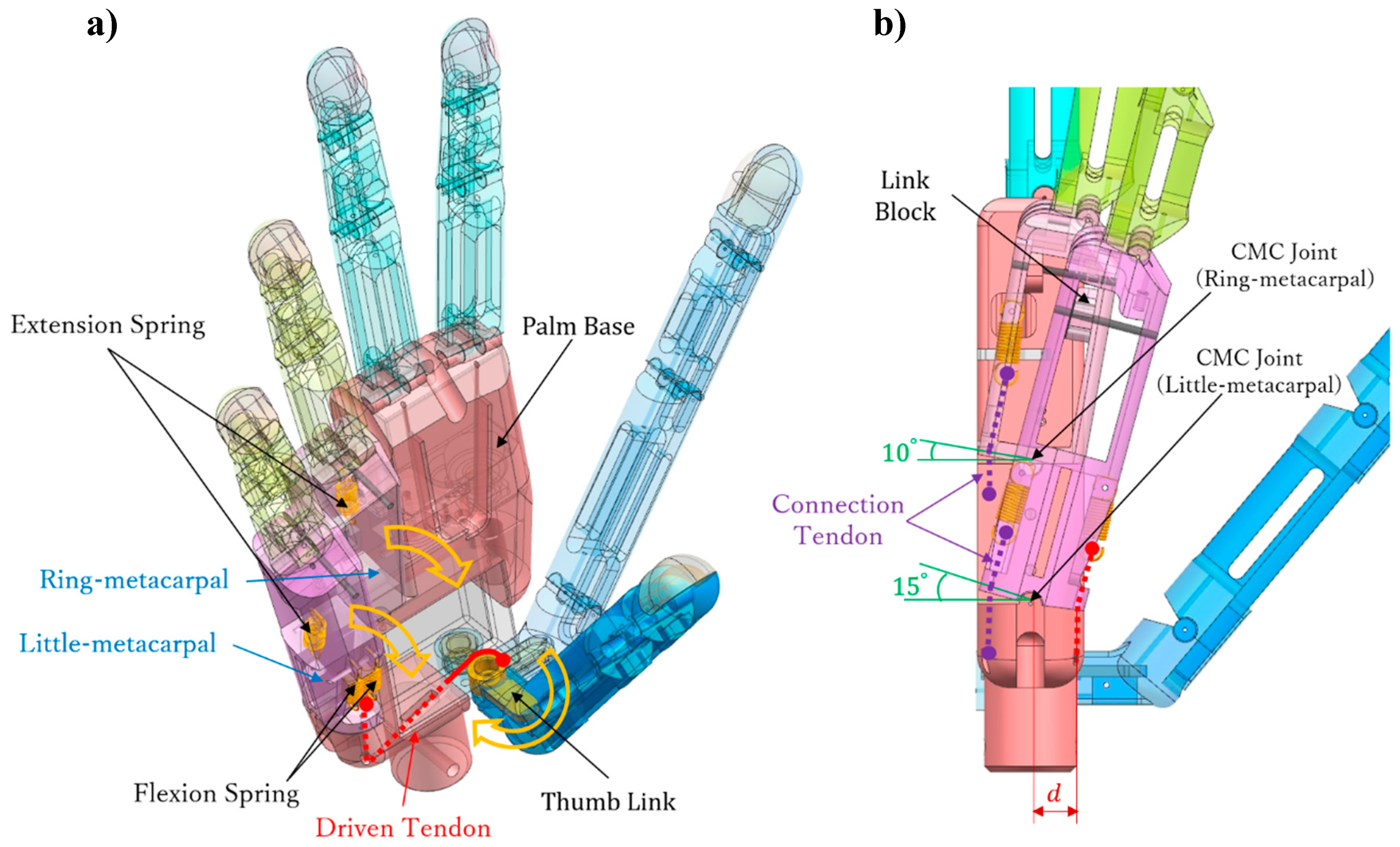
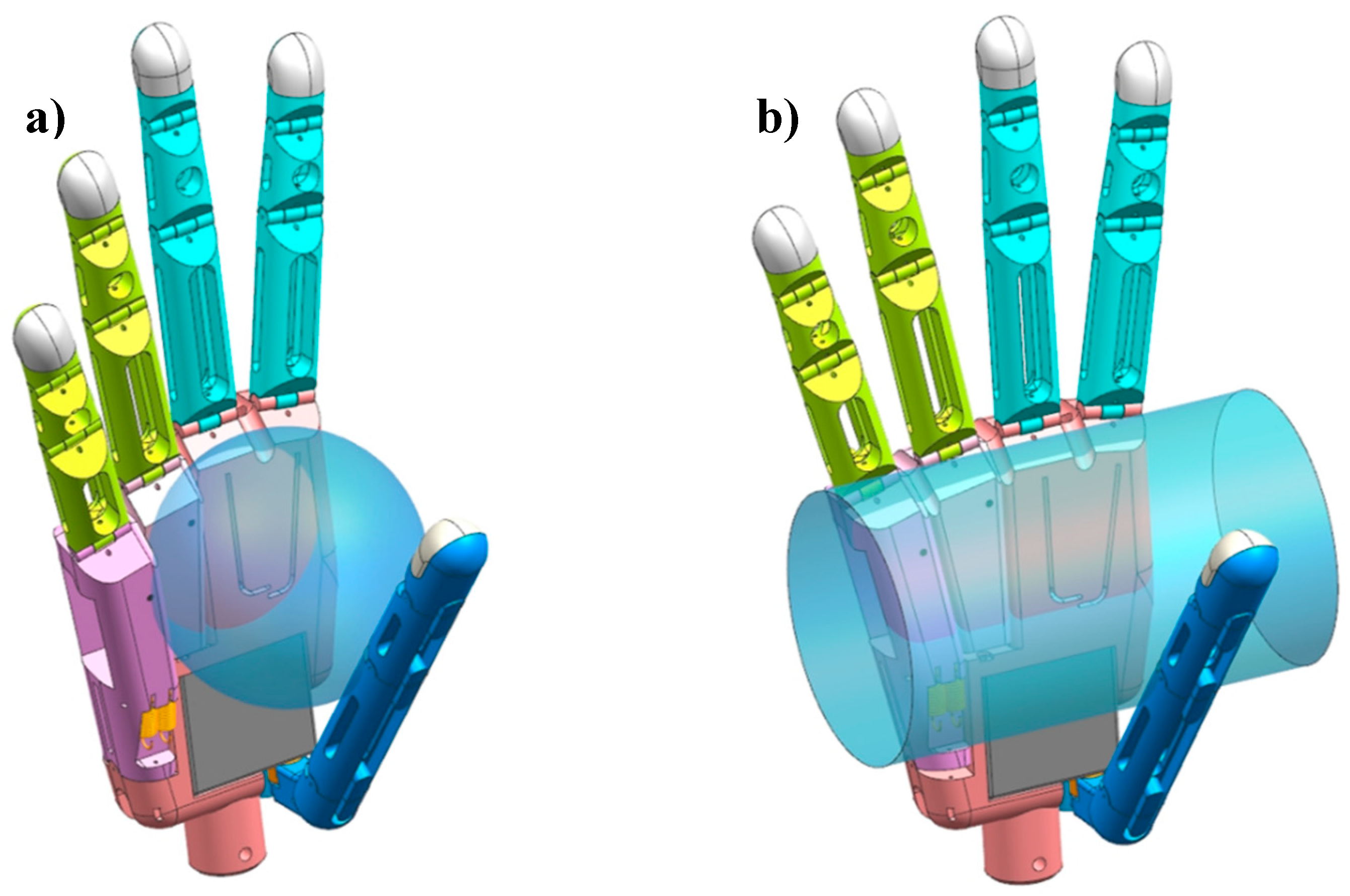
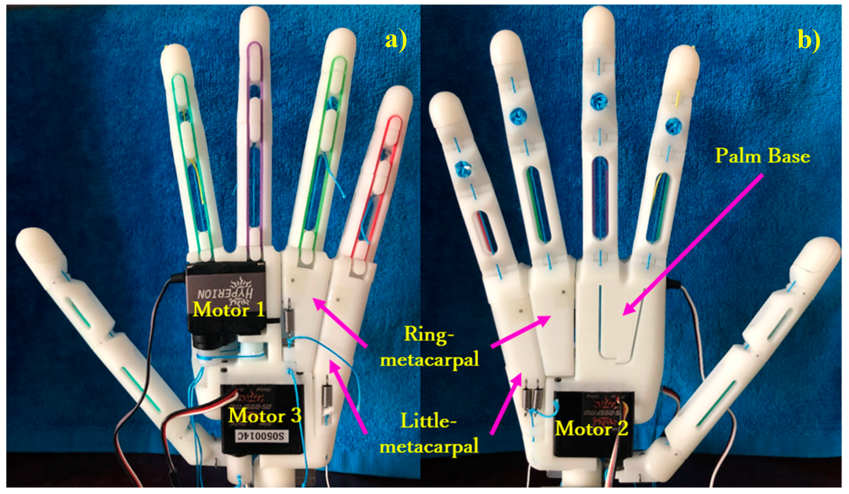
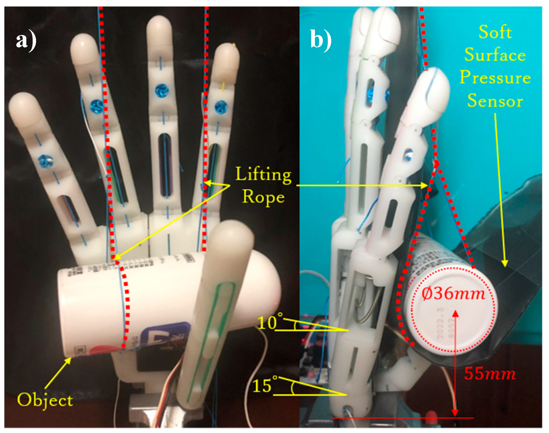
3.1. Palm Design
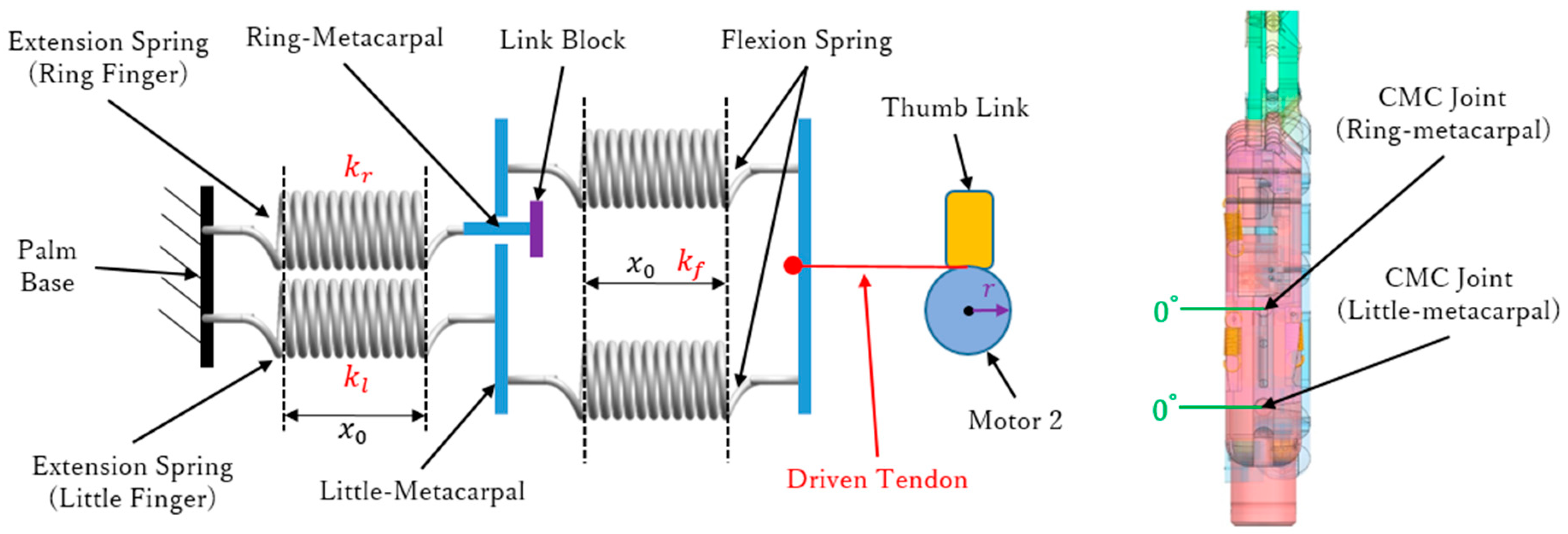
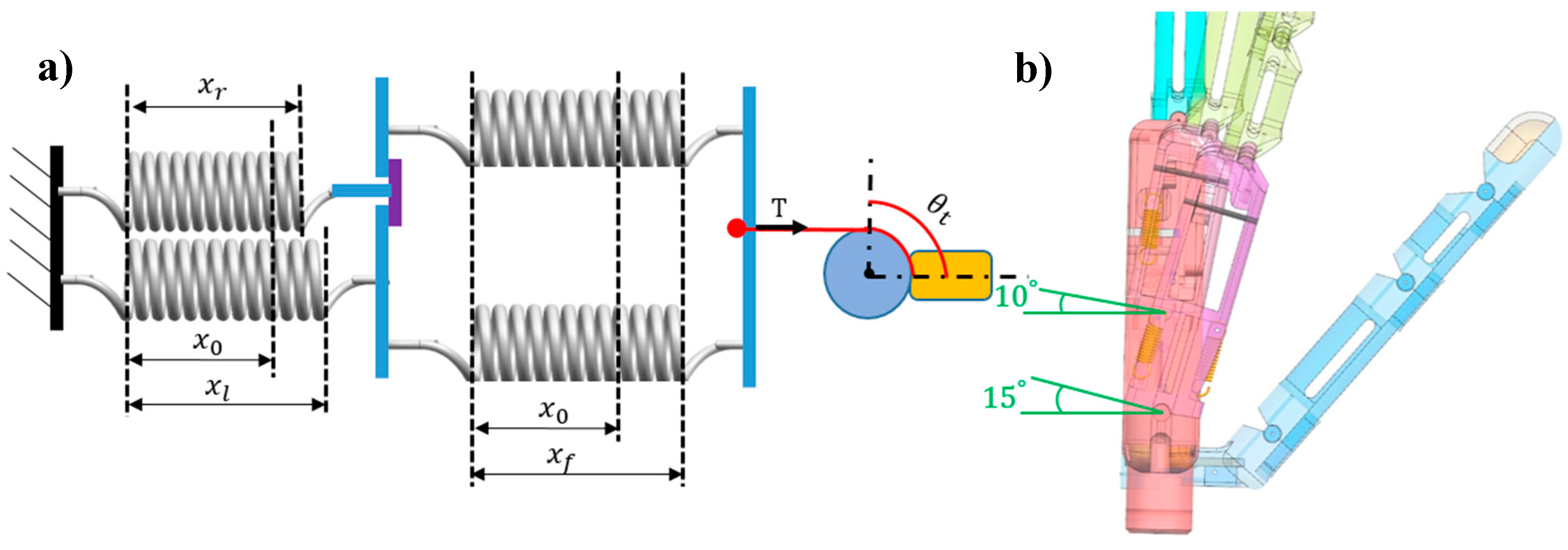
3.2. Arch Mechanism
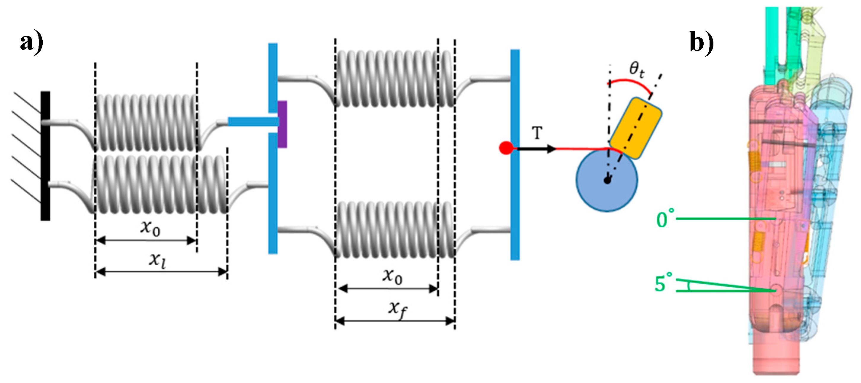
3.2.1. No-Load Stage
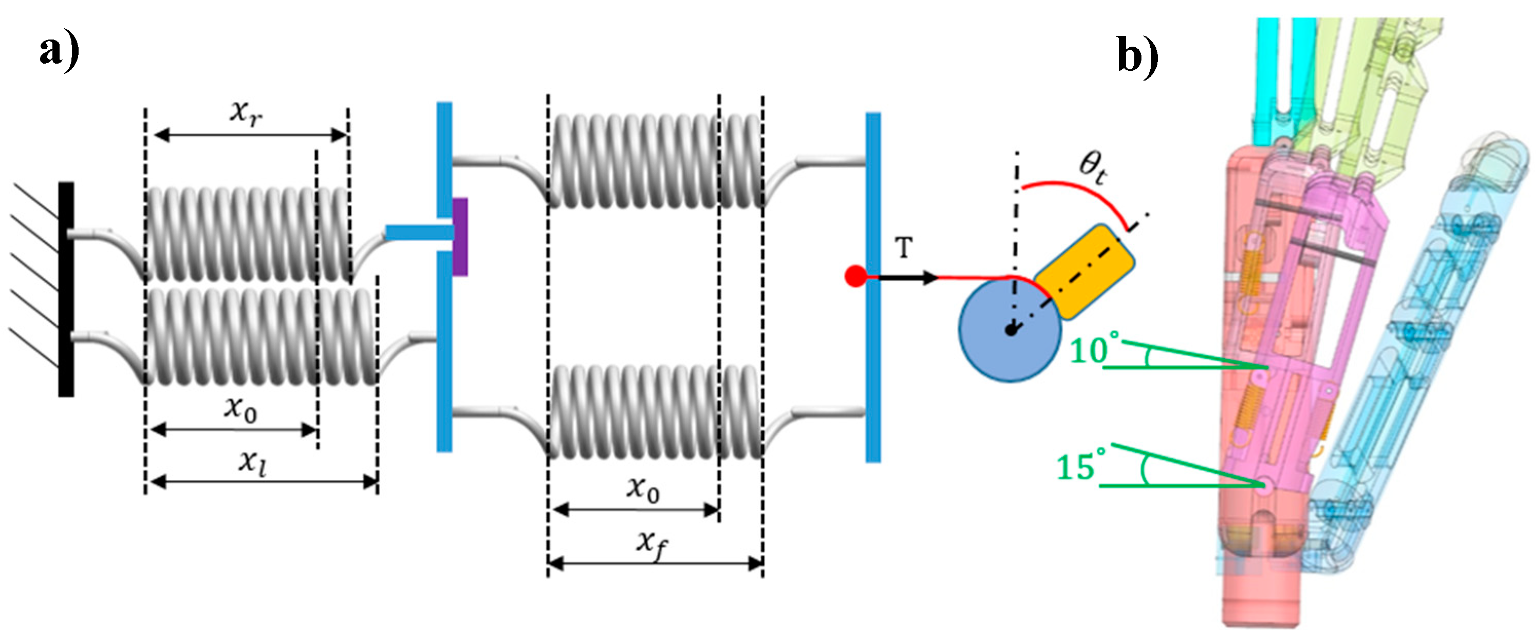
3.2.2. Load Stage
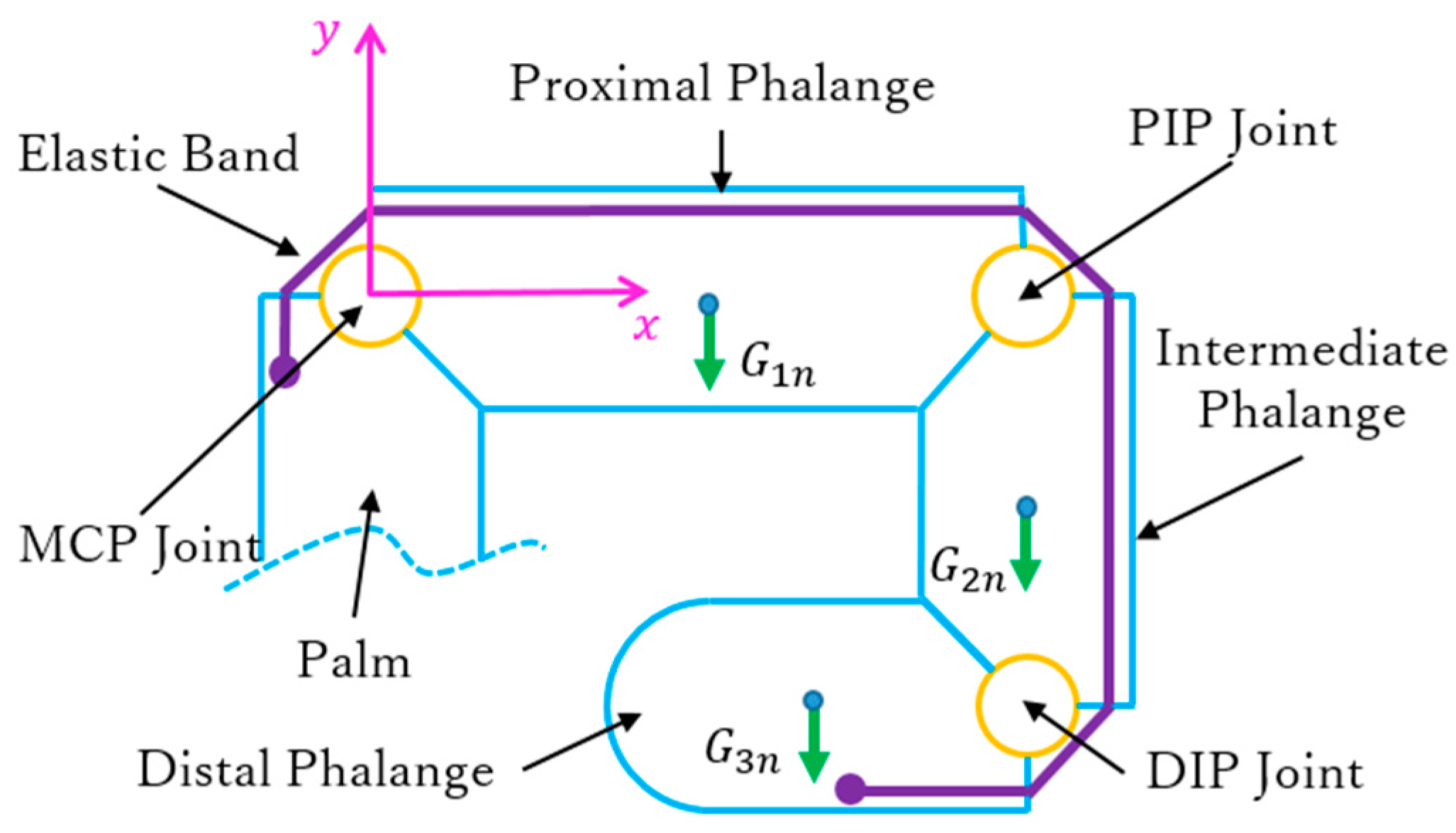
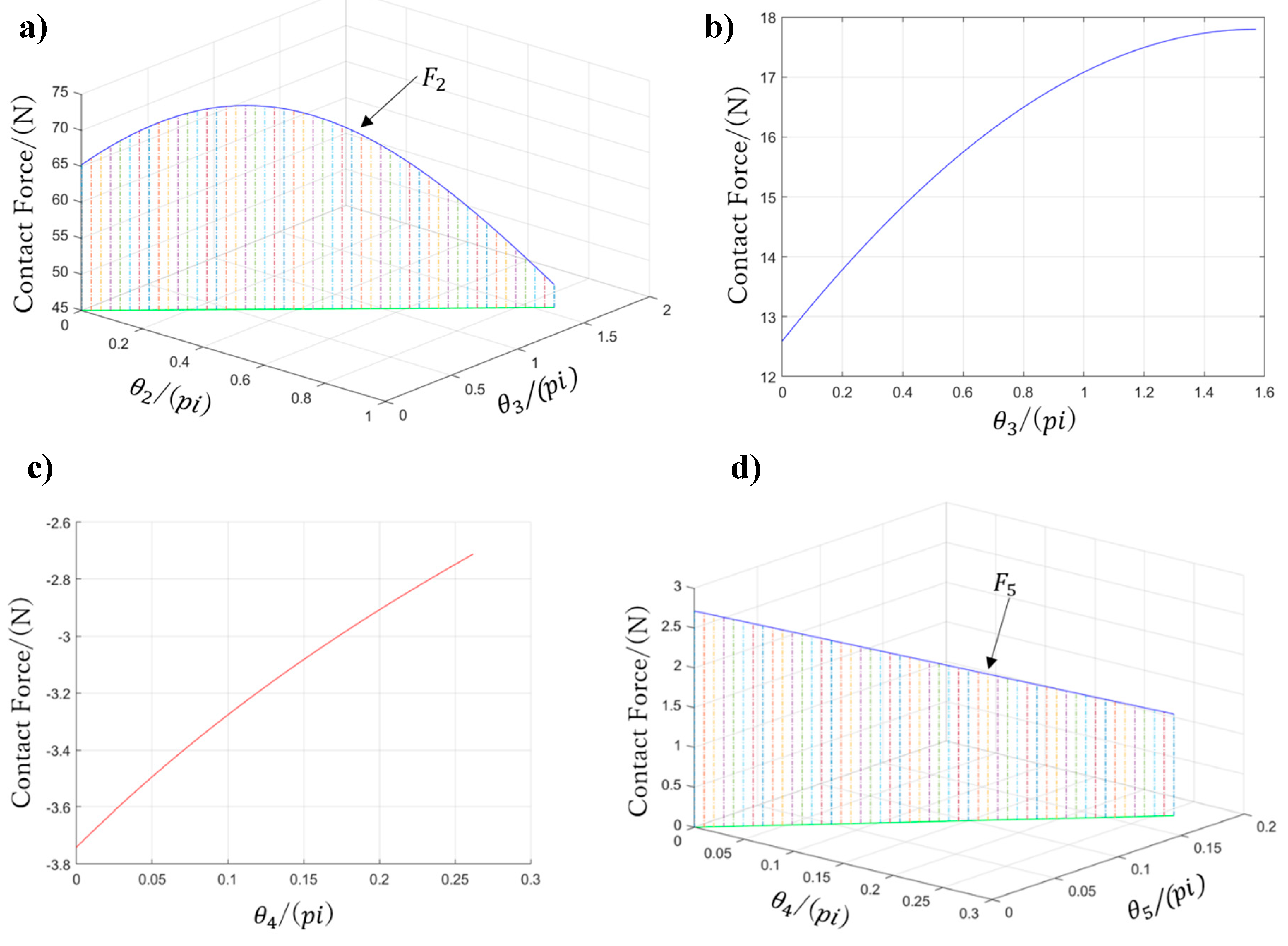
3.3. Kinematic and Static Analyses of Arch Function
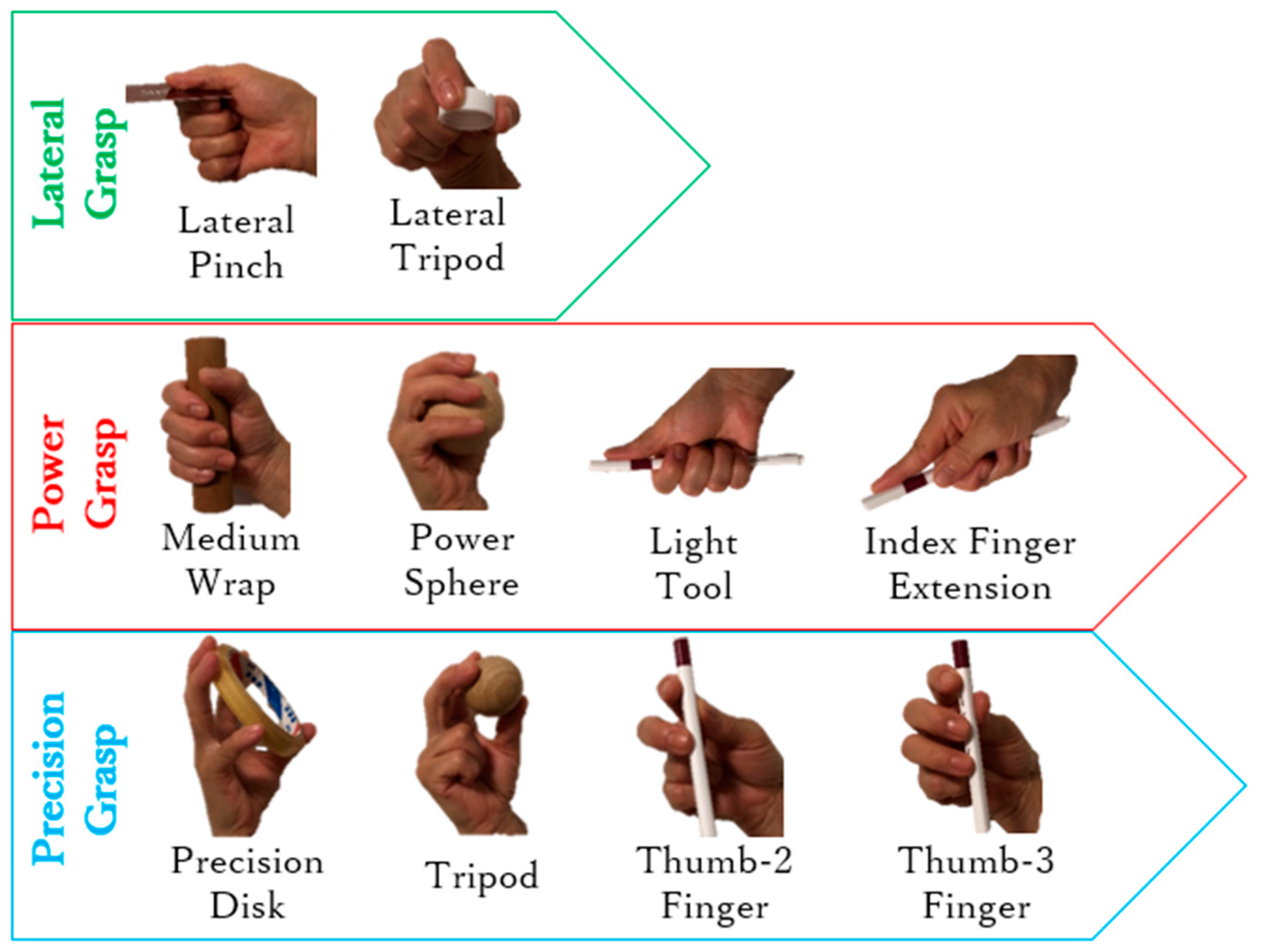
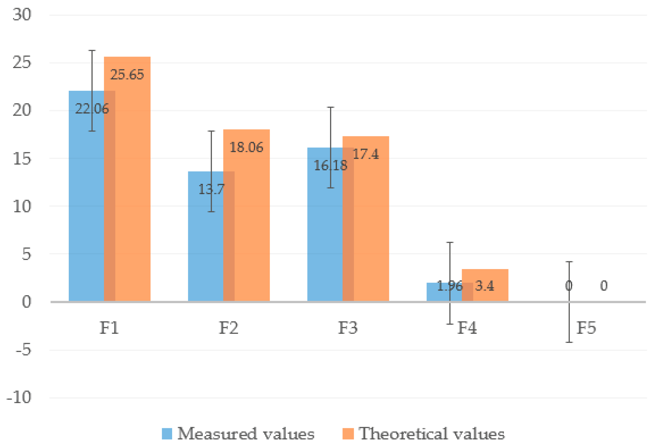
4. Experiments and Results
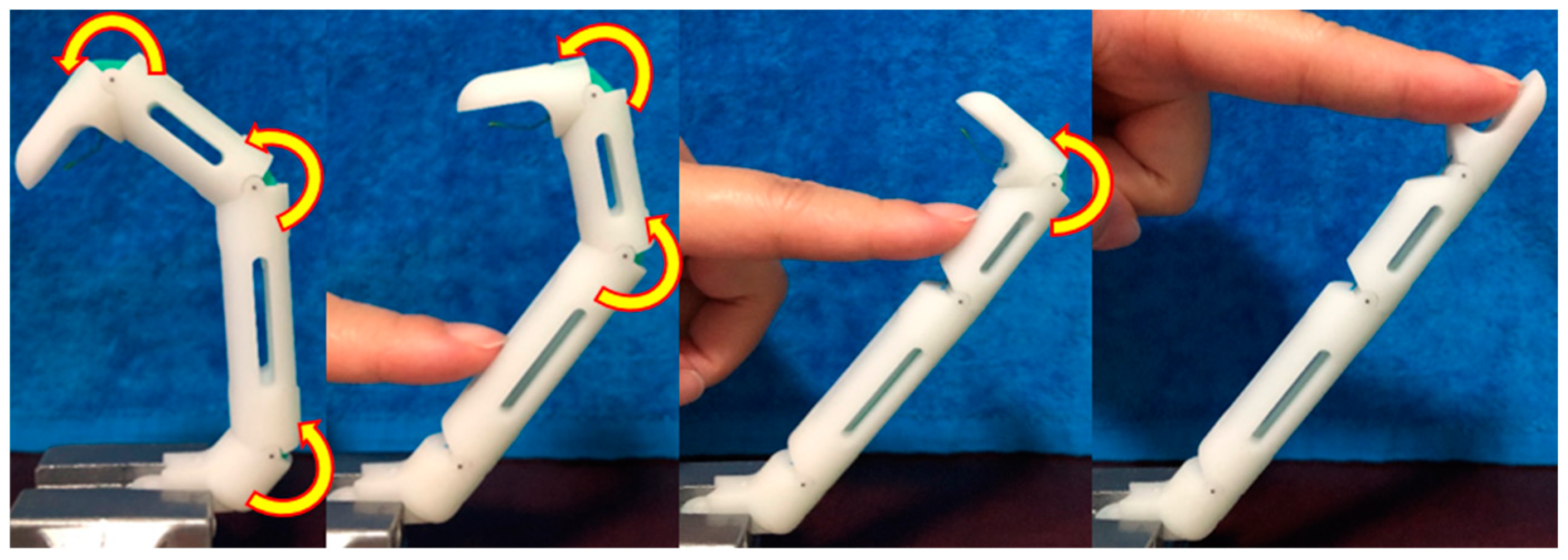
4.1. Finger Motion Verification
4.2. Arch Motion Verification
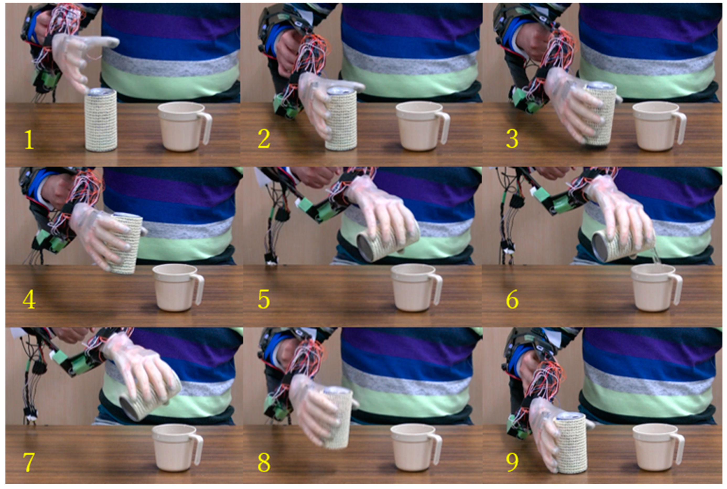
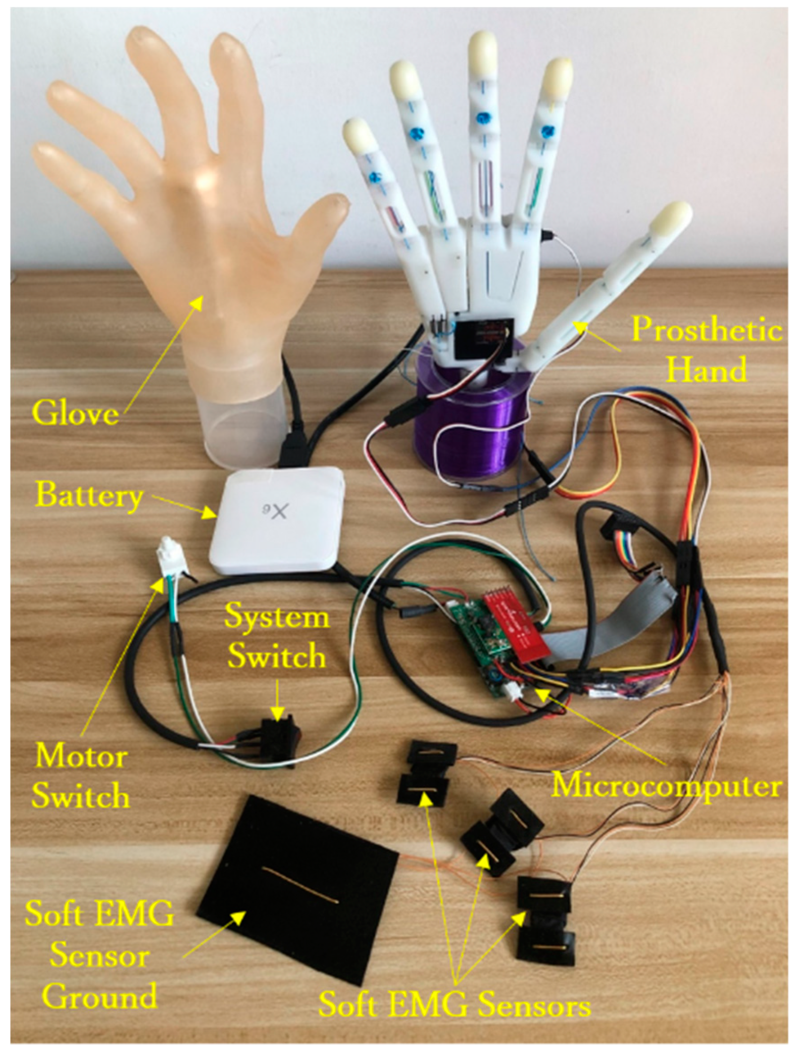
4.3. Intuitive EMG-Based Control
5. Conclusions
Author Contributions
Funding
Conflicts of Interest
References
- Feix, T. Anthropomorphic Hand Optimization Based on a Latent Space Analysis. Master’s Thesis, Technische Universitat Wien, Vienna, Austria, 2011. [Google Scholar]
- Anatomy of the Human Body. Available online: http://www.bartleby.com/107/ (accessed on 15 July 2013).
- Taylor, C.L.; Schwarz, R.J. The anatomy and mechanics of the human hand. Artif. Limbs 1955, 2, 22–35. [Google Scholar] [PubMed]
- Marieb, E.N.; Hoehn, K. Human Anatomy and Physiology, 7th ed.; Benjamin-Cummings Publishing Company: San Francisco, CA, USA, 2006. [Google Scholar]
- Schmidt, H.M.; Lanz, U. Surgical Anatomy of the Hand; Thieme: Stuttgart, Germany, 2004. [Google Scholar]
- Balasubramanian, R.; Santos, V.J. The Human Hand as an Inspiration for Robot Hand Development; Springer: Berlin/Heidelberg, Germany, 2014. [Google Scholar]
- Jones, L.A.; Lederman, S.J. Human Hand Function, 1st ed.; Oxford University Press: New York, NY, USA, 2006. [Google Scholar]
- Xu, Z. Design and Control of an Anthropomorphic Robotic Hand: Learning Advantages from the Human Body & Brain. Ph.D. Thesis, University of Washington, Seattle, WA, USA, 2015. [Google Scholar]
- Kyberd, P.J.; Wartenberg, C.; Sandsjö, L.; Jönsson, S.; Gow, D.; Frid, J.; Almström, C.; Sperling, L. Survey of upper extremity prosthesis users in sweden and the United Kingdom. J. Prosthet. Orthot. 2007, 19, 55–62. [Google Scholar] [CrossRef]
- Pylatiuk, C.; Schulz, S.; Döderlein, L. Results of an internet survey of myoelectric prosthetic hand users. Prosthet. Orthot. Int. 2007, 31, 362–370. [Google Scholar] [CrossRef] [PubMed]
- Biddiss, E.; Beaton, D.; Chau, T. Consumer design priorities for upper limb prosthetics. Disabil. Rehabil. Assist. Technol. 2007, 2, 346–357. [Google Scholar] [CrossRef] [PubMed]
- Upper Limb Prostheses—A Review of the Literature with a Focus on Myoelectric Hands. 2013. Available online: www.worksafebc.com/evidence (accessed on 23 February 2019).
- Bullock, I.; Zheng, J.; Rosa, S.; Guertler, C.; Dollar, A. Grasp frequency and usage in daily household and machine shop tasks. IEEE Trans. Haptics 2013, 6, 296–308. [Google Scholar] [CrossRef] [PubMed]
- Napier, J.R. The prehensile movements of the human hand. J. Bone Jt. Surg. 1956, 38–B, 902–913. [Google Scholar] [CrossRef]
- Feix, T.; Pawlik, R.; Schmiedmayer, H.; Romero, J.; Kragic, D. A Comprehensive Grasp Taxonomy. In Proceedings of the Robotics, Science and Systems Conference: Workshop Understanding the Human Hand for Advancing Robotic Manipulation, Seattle, WA, USA, June 2009. [Google Scholar]
- Cutkosky, M.R. On Grasp Choice, Grasp Models, and the Design of Hands for Manufacturing Tasks. IEEE Trans. Robot. Autom. 1989, 5, 269–279. [Google Scholar] [CrossRef]
- Zheng, J.; De, S.; Rosa, L.; Dollar, A. An Investigation of Grasp Type and Frequency in Daily Household and Machine Shop Tasks. In Proceedings of the 2011 IEEE International Conference on Robotics and Automation, Shanghai, China, 9–13 May 2011; pp. 4169–4175. [Google Scholar]
- Matsumoto, Y.; Nishida, Y.; Motomura, Y.; Okawa, Y. A Concept of Needs-Oriented Design and Evaluation of Assistive Robots Based on ICF. In Proceedings of the 2011 IEEE International Conference on Rehabilitation Robotics, Zurich, Switzerland, 29 June–1 July 2011. [Google Scholar]
- Santina, C.D.; Piazza, C.; Grioli, G.; Catalano, M.G.; Bicchi, A. Toward Dexterous Manipulation with Augmented Adaptive Synergies: The Pisa/II T SoftHand 2. IEEE Trans. Robot. 2018, 34, 1141–1156. [Google Scholar] [CrossRef]
- The Handroid. Available online: http://www.itk-pro.com/en/pro/ kindengisyu.htm (accessed on 3 March 2016).
- Wang, X.; Liu, Y.; Yang, D.; Li, N.; Jiang, L.; Liu, H. Progress in the biomechatronic design and control of a hand prosthesis. In Proceedings of the 2010 IEEE/RSJ International Conference on Intelligent Robots and Systems, Taipei, Taiwan, 18–22 October 2010. [Google Scholar]
- Dollar, A.M.; Howe, R.D. The Highly Adaptive SDM Hand: Design and Performance Evaluation. Int. J. Robot. Res. 2010, 29, 585–597. [Google Scholar] [CrossRef]
- Mason, M.T.; Rodriguez, A.; Srinivasa, S.S.; Vazquez, A.S. Autonomous Manipulation with a General-Purpose Simple Hand. Int. J. Robot. Res. 2011, 31, 688–703. [Google Scholar] [CrossRef]
- Birglen, L.; Gosselin, C.; Laliberté, T. Underactuated Robotic Hands; Springer: Berlin/Heidelberg, Germany; Quebec City, QC, Canada, 2010. [Google Scholar]
- ILimb Ultra. Available online: http://www.touchbionics.com/products/active-prostheses/i-limb-ultra (accessed on 19 March 2016).
- Michelangelo Prosthetic Hand. Available online: http://www.ottobockus.com/prosthetics/upper-limb-prosthetics/solution-verview/michelangelo-prosthetic-hand (accessed on 4 March 2016).
- Introducing the New AR10 Humanoid Robotic Hand. Available online: http://www.active8robots.com/robots/ar10-robotic-hand (accessed on 7 March 2016).
- Robotic Hands (Self-contained). Available online: http://www.prensilia.com/index.php?q=en/node/40 (accessed on 4 March 2016).
- Meka Robotics’ Humanoid Torso and Anthropomorphic Hands. Available online: http://www.hizook.com/blog/2009/10/18/meka-robotics-humanoid-torso-and-anthropomorphic-hands (accessed on 7 March 2016).
- Belter, J.T.; Dollar, A.M. Novel differential mechanism enabling two DoF from a single actuator: Application to a prosthetic hand. In Proceedings of the IEEE International Conference on Rehabilitation Robotics (ICORR), Seattle, WA, USA, 24–26 June 2013; pp. 1–6. [Google Scholar]
- Zhe, X.; Emanuel, T. Design of a Highly Biomimetic Anthropomorphic Robotic Hand towards Artificial Limb Regeneration. In Proceedings of the IEEE International Conference on Robotics and Automation (ICRA), Stockholm, Sweden, 16–21 May 2016; pp. 3485–3492. [Google Scholar]
- Kay, H.W.; Rakic, M. Specifications for electromechanical hands. In Proceedings of the 4th International Symposium on the External Control of Human Extremities, August 1973; pp. 137–155. [Google Scholar]
- Kapandji, A.I. Physiologie de l’ Appareil Locomoteur, 6th ed.; Maloine: Paris, France, 2005. [Google Scholar]
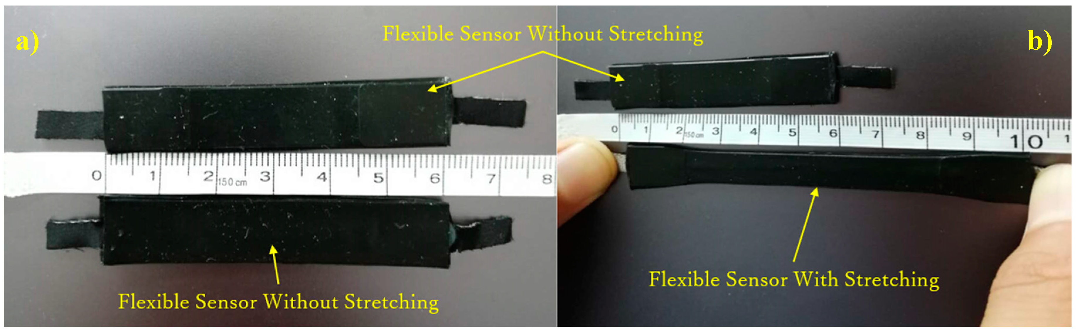
- Jiang, Y.; Togane, M.; Lu, B.; Yokoi, H. sEMG Sensor Using Polypyrrole-coated Nonwoven Fabric Sheet for Practical Control of Prosthetic Hand. Front. Neurosci. 2017, 11, 33. [Google Scholar] [CrossRef] [PubMed]
- Wu, X.; Liu, D.; Liu, M.; Chen, C.; Guo, H. Individualized Gait Pattern Generation for Sharing Lower Limb Exoskeleton Robot. IEEE Trans. Autom. Sci. Eng. 2018, 15, 1459–1470. [Google Scholar] [CrossRef]
- Liu, D.; Wu, X.; Du, W.; Wang, C.; Xu, T. Gait Phase Recognition for Lower-limb Exoskeleton with Only Joint Angular Sensors. Sensors 2016, 16, 1579. [Google Scholar] [CrossRef] [PubMed]
- Xu, T.; Yu, J.; Vong, C.; Wang, B.; Wu, X.; Zhang, L. Dynamic Morphology and Swimming Properties of Rotating Miniature Swimmers with Soft Tails. IEEE/ASME Trans. Mechatron. 2019, 24, 924–934. [Google Scholar] [CrossRef]
- Xu, T.; Guan, Y.; Liu, J.; Wu, X. Image-Based Visual Servoing of Helical Microswimmers for Planar Path Following. IEEE Trans. Autom. Sci. Eng. 2019, 1–9. [Google Scholar] [CrossRef]


© 2019 by the authors. Licensee MDPI, Basel, Switzerland. This article is an open access article distributed under the terms and conditions of the Creative Commons Attribution (CC BY) license (http://creativecommons.org/licenses/by/4.0/).
Share and Cite
Yong, X.; Jing, X.; Wu, X.; Jiang, Y.; Yokoi, H. Design and Implementation of Arch Function for Adaptive Multi-Finger Prosthetic Hand. Sensors 2019, 19, 3539. https://doi.org/10.3390/s19163539
Yong X, Jing X, Wu X, Jiang Y, Yokoi H. Design and Implementation of Arch Function for Adaptive Multi-Finger Prosthetic Hand. Sensors. 2019; 19(16):3539. https://doi.org/10.3390/s19163539
Chicago/Turabian StyleYong, Xu, Xiaobei Jing, Xinyu Wu, Yinlai Jiang, and Hiroshi Yokoi. 2019. "Design and Implementation of Arch Function for Adaptive Multi-Finger Prosthetic Hand" Sensors 19, no. 16: 3539. https://doi.org/10.3390/s19163539
APA StyleYong, X., Jing, X., Wu, X., Jiang, Y., & Yokoi, H. (2019). Design and Implementation of Arch Function for Adaptive Multi-Finger Prosthetic Hand. Sensors, 19(16), 3539. https://doi.org/10.3390/s19163539