3D Virtual Reconstruction of the Ancient Roman Incile of the Fucino Lake

 , ,
, , 
 and
and
Abstract
1. Introduction
2. Related Works
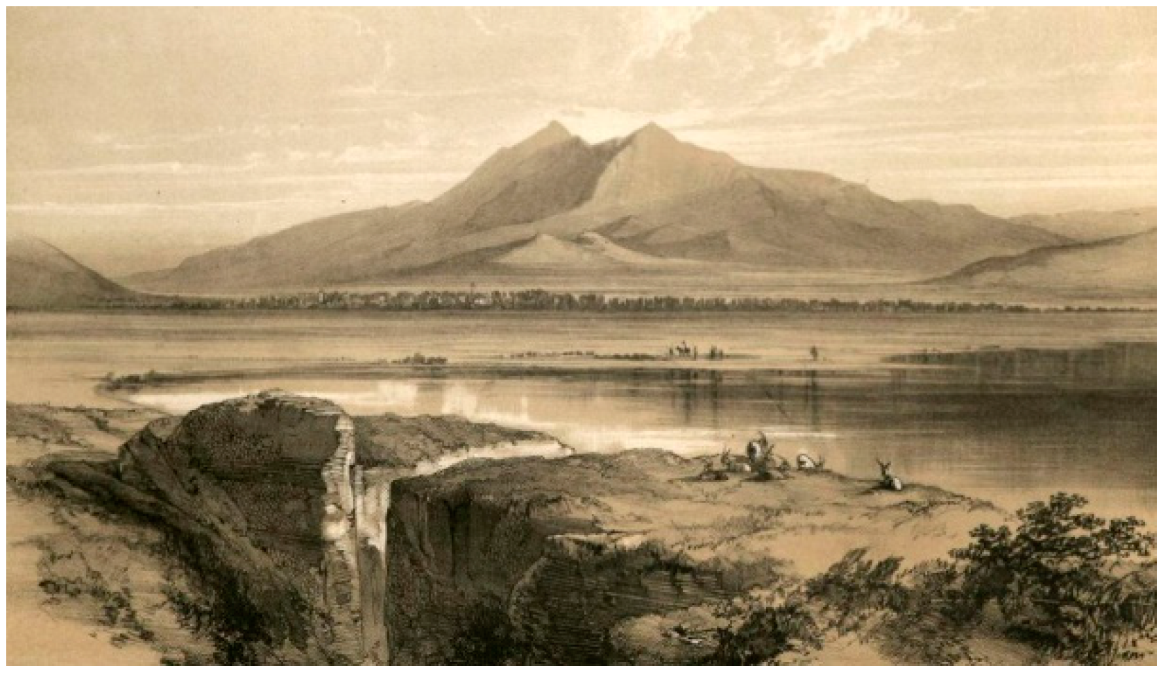
3. The Iconographic Sources
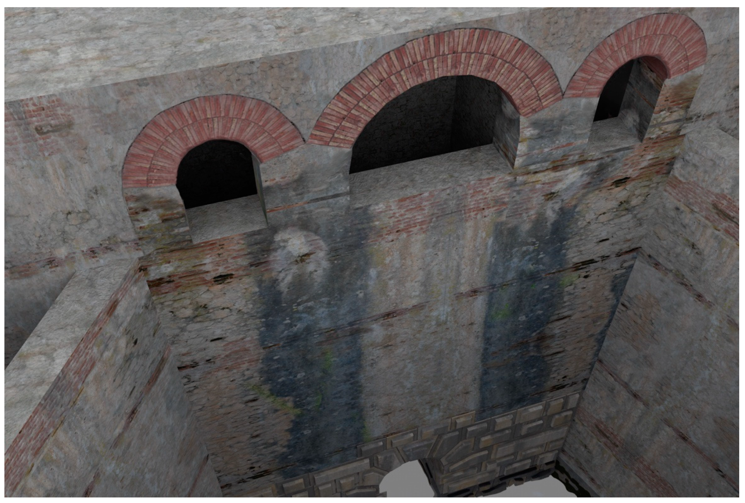
4. The 3D Virtual Reconstruction
4.1. Quantitative Description
4.2. The Relocation of the Roman Incile
5. Results and Conclusions
Author Contributions
Funding
Conflicts of Interest
References
- Galeazzi, C.; Germani, C.; Parise, M. Gli antichi emissari artificiali dei bacini endoreici. Opera Ipogea 2012, 1, 3–10. [Google Scholar]
- Di Angelo, L.; Di Stefano, P.; Pane, C. The 3D virtual reconstruction of an engineering work of the past. In Proceedings of the IOP Conference Series: Materials Science and Engineering, Florence, Italy, 16–18 May 2018; IOP: Bristol, England. [Google Scholar]
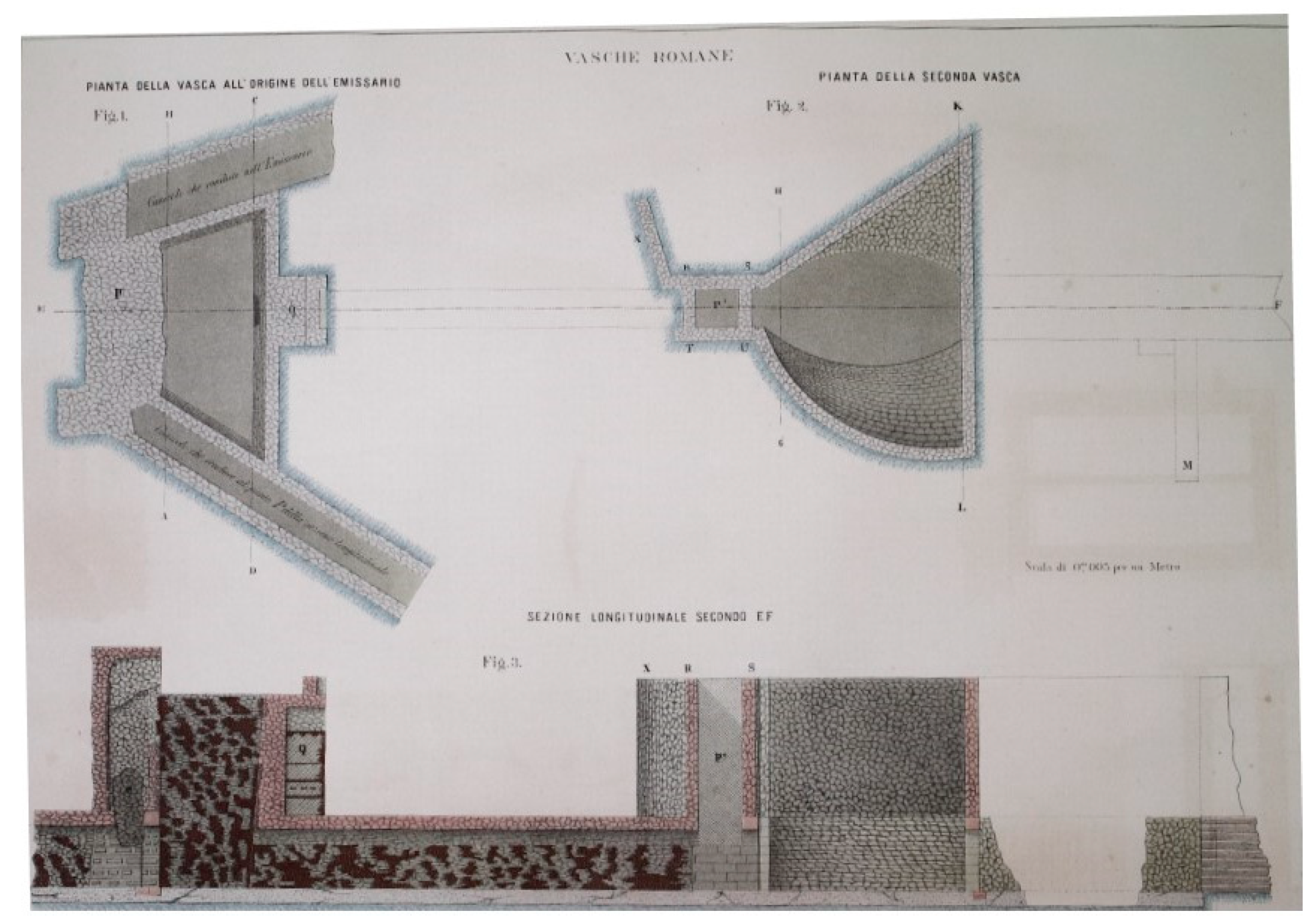
- Brisse, A.; De Rotrou, L. Prosciugamento del Lago Fucino fatto eseguire da Sua Eccellenza il Principe Alessandro Torlonia: Descrizione storica e tecnica in due volumi ed un atlante fatta dal Comm. In Alessandro Brisse ingegnere in capo del prosciugamento e Cav. Leone de Rotrou già presidente capo dell’ amministrazione, Tipografia della SC di Propaganda Fide; l'OPAC: Atlas, Greece, 1883. (In Italian) [Google Scholar]
- Pocobelli, D.P.; Boehm, J.; Bryan, P.; Still, J.; Grau-Bové, J. BIM for heritage science: A review. Heritage Sci. 2018, 6. [Google Scholar] [CrossRef]
- Guidi, G.; Russo, M.; Ercoli, S.; Remondino, F.; Rizzi, A.; Menna, F. A Multi-Resolution Methodology for the 3D Modeling of Large and Complex Archeological Areas. Int. J. Archit. Comput. 2009, 7, 39–55. [Google Scholar] [CrossRef]
- Di Angelo, L.; Di Stefano, P.; Morabito, A.E.; Pane, C. Measurement of constant radius geometric features in archaeological pottery. Measurement J. Int. Measurement Confed. 2018, 124, 138–146. [Google Scholar] [CrossRef]
- Remondino, F.; Rizzi, A. Reality-based 3D documentation of natural and cultural heritage sites-techniques, problems, and examples. Appl. Geomatics 2010, 2, 85–100. [Google Scholar] [CrossRef]
- Barsanti, S.G.; Remondino, F.; Visintini, D. Photogrammetry and laser scanning for archaeological site 3D modeling-Some critical issues. Present at the 2nd Workshop on The New Technologies for Aquileia’, Aquileia, Italy, 25 June 2012; Volume 948, pp. B1–B10. [Google Scholar]
- Callieri, M.; Chica, A.; Dellepiane, M.; Besora, I.; Corsini, M.; Moyé, S.J.; Ranzuglia, G.; Scopigno, R.; Brunet, P. Multiscale acquisition and presentation of very large artifacts: The case of portalada. J. Comput. Cult. Herit. 2011, 3, 14. [Google Scholar] [CrossRef]
- Vosselman, G.; Maas, H.G. Airborne and Errestrial Aser Canning, 1st ed.; Taylor & Francis CRC Press: Boca Raton, FL, USA, 2010. [Google Scholar]
- Blais, F. A review of 20 years of Range Sensors Development. J. Electron. Imaging 2004, 13, 231–240. [Google Scholar] [CrossRef]
- Remondino, F. El-hakim, Image-based 3D modelling: A review. Photogramm. Rec. 2006, 21, 269–291. [Google Scholar] [CrossRef]
- Barazzetti, L.; Forlani, G.; Remondino, F.; Roncella, R.; Scaioni, M. Experiences and achievements in automated image sequence orientation for close-range photogrammetric projects. SPIE 2011, 8085, 80850F. [Google Scholar] [CrossRef]
- Westoby, M.J.; Brasington, J.; Glasser, N.F.; Hambrey, M.J.; Reynolds, J.M. Structure-from-motion’ photogrammetry: a low-cost, effective tool for geoscience applications. Geomorphology 2012, 179, 300–314. Available online: http://www.sciencedirect.com/science/article/pii/S0169555X12004217 (accessed on 5 September 2012). [CrossRef]
- Remondino, F.; Spera, M.G.; Nocerino, E.; Menna, F.; Nex, F. State of the art in high density image matching. Photogram. Rec. 2014, 29, 144–166. [Google Scholar] [CrossRef]
- Micoli, L.; Barsanti, S.G.; Malik, U.; Guidi, G. 3D data integration for the digital reconstruction of cultural heritage monuments. In Proceedings of the IOP Conference Series: Materials Science and Engineering, Florence, Italy, 16–18 May 2018; IOP: Bristol, England; Volume 364. [Google Scholar]
- Al-Ruzouq, R.; Venkatachalam, S.; Abueladas, A.; Abu Dabous, S. Geomatics for economic archaeological documentation and management. Appl. Geomatics 2018, 10, 341–360. [Google Scholar] [CrossRef]
- Rodríguez-Gonzálvez, P.; Muñoz-Nieto, A.L.; DelPozo, S.; Sanchez-Aparicio, L.J.; Gonzalez-Aguilera, D.; Micoli, L.; Barsanti, S.G.; Guidi, G.; Mills, J.; Fieber, K.; et al. 4D reconstruction and visualization of cultural heritage: Analyzing our legacy through time. In Proceedings of the International Archives of the Photogrammetry, Remote Sensing and Spatial Information Sciences-ISPRS Archives, Nafplio, Greece, 1–3 March 2017; Volume XLII (2W3), pp. 609–616. [Google Scholar]
- Guidi, G.; Russo, M.; Angheleddu, D. Digital reconstruction of an archaeological site based on the integration of 3D data and historical sources. In Proceedings of the International Archives of the Photogrammetry, Remote Sensing and Spatial Information Sciences-ISPRS Archives, Trento, Italy, 25–26 February 2013; Volume XL- 5/W1, pp. 99–105. [Google Scholar]
- Bitelli, G.; Dellapasqua, M.; Girelli, V.A.; Sbaraglia, S.; Tini, M.A. Historical photogrammetry & terrestrial laser scanning for the 3D virtual reconstruction of destroyed structures: A case study in Italy. In Proceedings of the International Archives of the Photogrammetry, Remote Sensing and Spatial Information Sciences-ISPRS Archives, Nafplio, Greece, 1–3 March 2017; Volume XLII-5/W1, pp. 113–119. [Google Scholar]
- Haugstvedt, A.C.; Krogstie, J. Mobile augmented reality for cultural heritage: A technology acceptance study. In Proceedings of the ISMAR 2012-11th IEEE International Symposium on Mixed and Augmented Reality, Atlanta, GA, USA, 5–8 November 2012. [Google Scholar]
- Bernardini, A.; Delogu, C.E.; Pallotti, L. Costantini, Living the Past: Augmented Reality and Archeology. In Proceedings of the IEEE International Conference on Multimedia and Expo Workshops, Melbourne, Austrilia, 9–13 July 2012; pp. 354–357. [Google Scholar]
- Vanoni, D.; Seracini, M.; Kuester, F. ARtifact: Tablet-based augmented reality for interactive analysis of cultural artifacts. In Proceedings of the IEEE International Symposium on Multimedia, ISM, Irvine, CA, USA, 10–12 December 2012; pp. 44–49. [Google Scholar]
- Quattrini, R.; Pierdicca, R.; Frontoni, E.; Barcaglioni, R. Virtual reconstruction of lost architectures: From the TLS survey to AR visualization. In Proceedings of the International Archives of the Photogrammetry, Remote Sensing and Spatial Information Sciences—ISPRS Archives, Prague, Czech Republic, 12–19 July 2016; Volume 41, pp. 383–390. [Google Scholar]
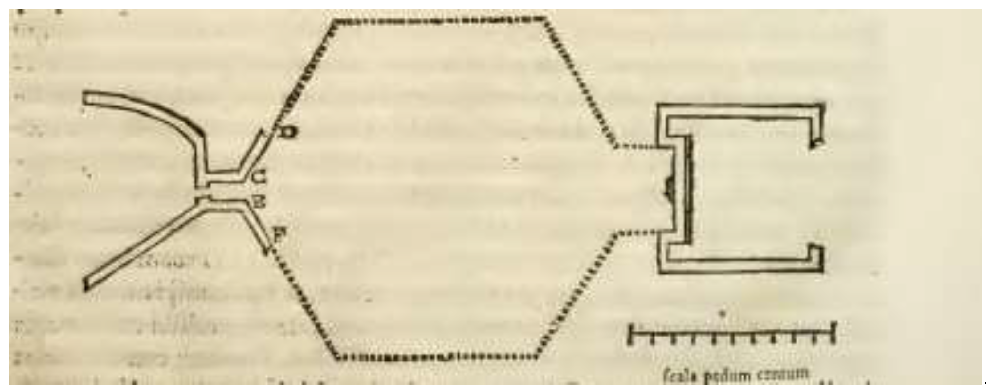
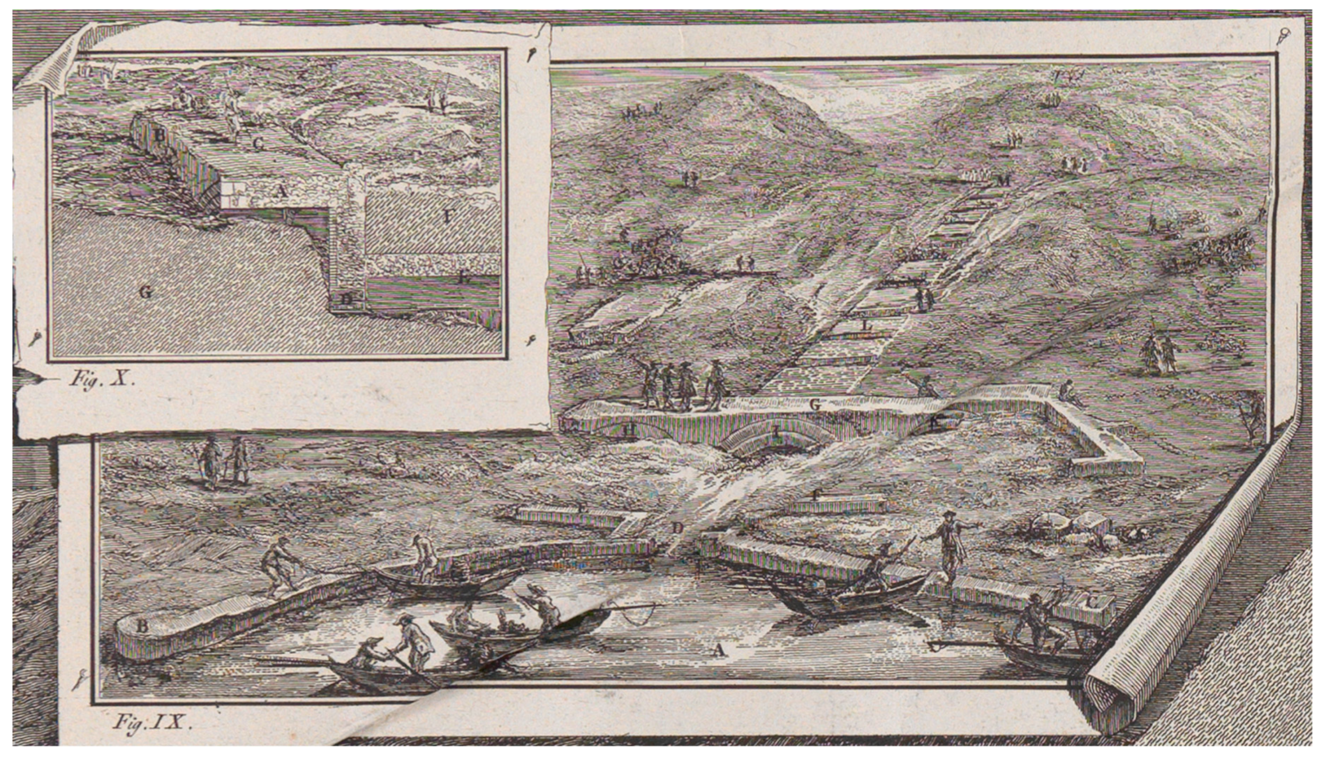
- Fabretti, R.G. De columna Traiani syntagma Accesserunt Explicatio veteris tabellae anaglyphae Homeri Iliadem atque ex Stesichoro Arctino et Lesche Ilii excidium continentis & Emissarii lacus Fucini descriptio; Ex typographia Joannis Francisci de Buagnis. Superiorum Permissu; ex officinâ Nicolai Angeli Tinassij: Roma, Italy, 1690; pp. 385–420. (In Italian) [Google Scholar]
- Lear, E. Illustrated Excurtions in Italy; Thomas McLean: London, UK, 1846. [Google Scholar]
- Giraudi, C.; Galadini, F.; Galli, P. Studi geologici sugli antichi canali di bonifica del lago Fucino, in Il Fucino e le aree limitrofe nell’antichità. Atti del II convegno di archeologia in ricordo di Antonio Maria Radmilli e Giuliano Cremonesi. Celano, Museo delle Paludi; Archeoclub d’Italia, Sez. della Marsica: Avezzano, Italy, 2001; pp. 363–370. [Google Scholar]


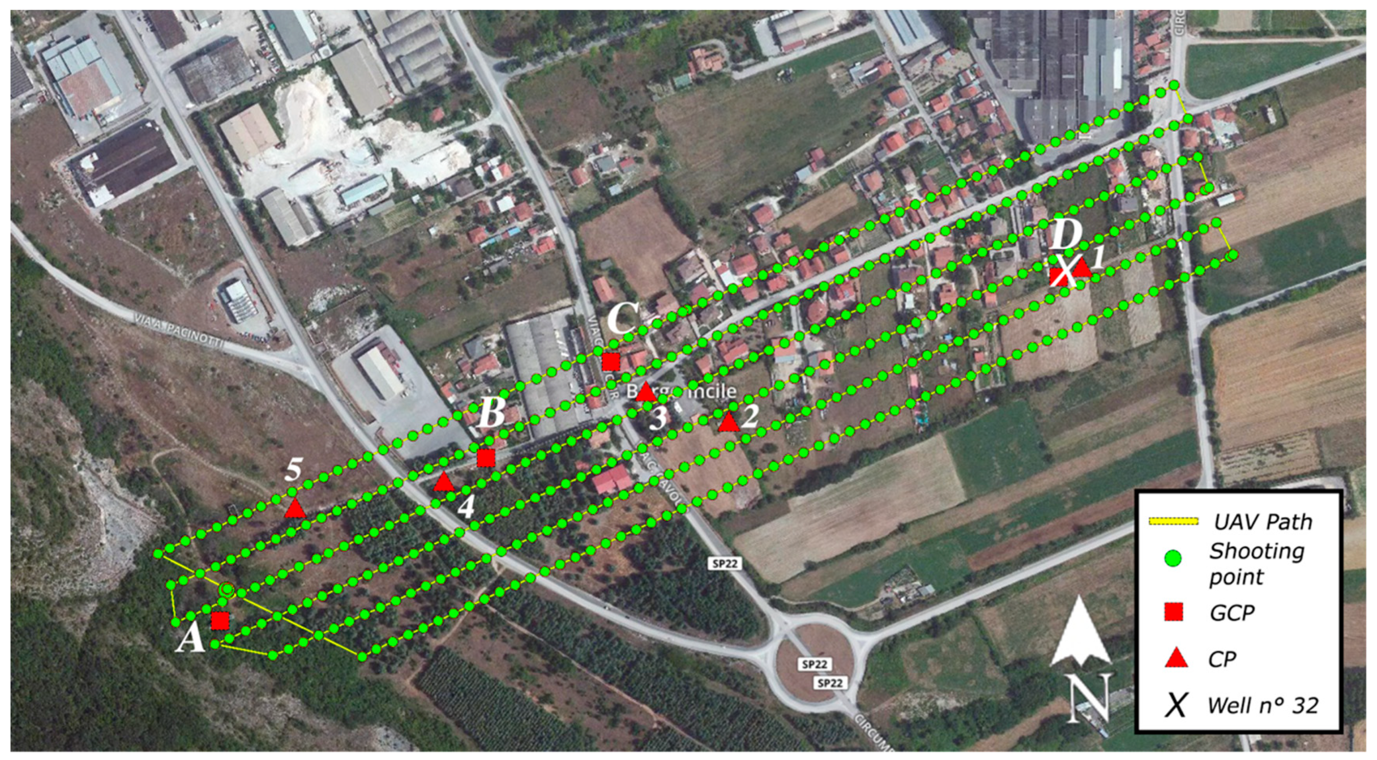
| Type of UAV | |
| Micro UAV Quadricopter | |
| Optical sensor | |
| Parameter | Value |
| Focal length | 35 mm |
| Sensor dimensions | 6.17 mm × 4.55 mm |
| Resolution | 13 Mpixel |
| Pixel dimension | 10 µm |
| FoV | 78° |
| Parameter | Value | Parameter | Value |
|---|---|---|---|
| Flight altitude from SP | 70 m | GSD | 4 cm |
| Front overlap | 75 % | GCPs | 4 |
| Side overlap | 65 % | Viewing angle | 0 deg |
| Flight speed | 6 m/s |
| Point Cloud. | 3D Mesh |
|---|---|
| Image scale = 1:1 | Maximum octree depth = 14 |
| Points density = Optimal | Texture size = 16,384 × 16,384 |
| Minimum number of matches = 3 | Decimation criteria = qualitative (sensitive) |
| Tie-points = 10,000 Coordinate accuracy = High |
| Point | Altitude Survey 1996 | Measured Altitude | Error |
|---|---|---|---|
| 1 | 666.9 m | 666.9 m (RIF) | - |
| 2 | 674.0 m | 673.8 m | 0.20 m |
| 3 | 677.4 m | 677.45 m | 0.05 m |
| 4 | 690.5 m | 690.1 m | 0.40 m |
| 5 | 699.3 m | 698.5 m | 0.80 m |
© 2019 by the authors. Licensee MDPI, Basel, Switzerland. This article is an open access article distributed under the terms and conditions of the Creative Commons Attribution (CC BY) license (http://creativecommons.org/licenses/by/4.0/).
Share and Cite
Di Angelo, L.; Di Stefano, P.; Guardiani, E.; Morabito, A.E.; Pane, C. 3D Virtual Reconstruction of the Ancient Roman Incile of the Fucino Lake. Sensors 2019, 19, 3505. https://doi.org/10.3390/s19163505
Di Angelo L, Di Stefano P, Guardiani E, Morabito AE, Pane C. 3D Virtual Reconstruction of the Ancient Roman Incile of the Fucino Lake. Sensors. 2019; 19(16):3505. https://doi.org/10.3390/s19163505
Chicago/Turabian StyleDi Angelo, Luca, Paolo Di Stefano, Emanuele Guardiani, Anna Eva Morabito, and Caterina Pane. 2019. "3D Virtual Reconstruction of the Ancient Roman Incile of the Fucino Lake" Sensors 19, no. 16: 3505. https://doi.org/10.3390/s19163505
APA StyleDi Angelo, L., Di Stefano, P., Guardiani, E., Morabito, A. E., & Pane, C. (2019). 3D Virtual Reconstruction of the Ancient Roman Incile of the Fucino Lake. Sensors, 19(16), 3505. https://doi.org/10.3390/s19163505