1. Introduction
The Internet of Things (IoT) refers to objects (specific and everyday ones) that can be connected through Internet networks due to the embedding of electronics. Therefore, IoT is the migration of the Internet beyond people. The devices can communicate and interact with others over the Internet, and they can be remotely monitored and controlled.
IoT has not fully penetrated consumers’ daily life with wearable devices yet. Three main factors affect the lagging status of consumer IoT technology: Feasibility, reliability of the connection between devices, and functionality of devices. However, wearable technology is already being developed and has a bright future in healthcare with the passive monitoring of vital statistics. The wearables market is still in the early phases of expansion, and currently dominated by health, wellness, and activity tracking devices—despite industry developments pointing to an increasing number of use cases. The wearables industry is thus involved in finding the use cases that will drive mass adoption by the consumers. Furthermore, wearable devices are, nowadays, at the heart of just about every discussion related to the IoT, and the full range of new capabilities which pervasive connectivity can bring.
Wearable electronics (WE), by virtue of an IP address, join the IoT and, as an additional advantage, do not have to exist as standalone devices. People everywhere will be able to interact with things by using WE [
1,
2,
3] and the IoT.
During the last decade we have witnessed a great development concerning flexible and/or miniaturized electronic devices for facilitating their integration in handheld equipment and/or in clothing. The advances regarding the design and fabrication of antennas [
4,
5,
6,
7,
8,
9] based on new materials [
10,
11,
12,
13,
14] and the use of innovative manufacturing techniques [
14,
15,
16,
17,
18,
19,
20] are key steps towards these WE.
As previously mentioned, a large market is foreseen in the near future for devices and emerging technologies with applications in 5G and IoT. For these new standard definitions, a wide variety of frequency bands are considered, both below 6GHz and at much upper frequencies (such as 24 GHz, 28–29 GHz, 60 GHz, and even higher values), with emphasis on ISM bands. With regard to the IoT, the preferred frequencies traditionally allocated for WLAN (around 2.4 GHz, 3.6 GHz, 4.9 GHz, 5 GHz, 5.9 GHz) and wireless sensor network communications (ZigBee, Bluetooth, RFID, NFC,….) are mostly around 2.45 GHz [
10,
11,
21,
22]. The reasons behind such preferences are the lower losses and the know-how, concerning not only the channel characterization, but also the previously developed electronics. Furthermore, frequencies below 1 GHz [
23]—such as 900 MHz and 700 MHz—are also considered for some 5G applications, although frequency re-farming is still pending in some countries. In view of these perspectives, the design of flexible and/or miniaturized antennas suitable for integration in next-generation devices is of great interest, although challenging.
Wearable electronics (WE) are enabled by the miniaturization and integration of components. Cameras, sensors, speakers, computer chips, and other components continue getting smaller while becoming more capable. The same applies to the antennas, as key parts of wearable communication systems. However, the textile dielectrics generally used in WE have a low relative dielectric permittivity ε
r (ranging from 1.17 of fleece to 2.95 of leather) [
15], which does not allow for reducing the size of the antennas at frequencies below 6GHz. Other non-textile employed materials, such as polystyrene foam, exhibit even lower values (ε
r = 1.02); the only one reporting a higher value is neoprene rubber (ε
r = 5.2), which is used, for example, in garments for watersports. The development and use of novel flexible dielectrics, with much higher relative dielectric permittivity than textiles and the mentioned ones for WE, needs to be explored. However, maintaining the flexibility while increasing the relative dielectric permittivity is a great challenge.
This work aims to design and manufacture an ultra-thin, flexible antenna based on a novel ceramic material, ENrG’s Thin E-Strate®, for IoT applications at frequencies around 2.7 GHz and 5.8 GHz (covering several of the intended bands), and compare its dimensions and performance (concerning matching and radiation properties) with the ones obtained using conventional rigid Arlon 25N dielectric and flexible polypropylene substrates.
This contribution is organized as follows: First the characteristics of the novel flexible ceramic material are described, as well as the ones of the conventional Arlon 25N and polypropylene. Then, the CPW-fed antenna design based on the three materials is presented and the obtained results are compared based on simulation. Prototypes of the designed antenna are fabricated using two different metallization techniques and their performance is compared with the simulation in terms of return losses. The best prototype of the antenna obtained on ENrG’s Thin E-Strate is then compared with a prototype on Arlon 25N, based on radiation properties obtained through measurements in an anechoic chamber. Finally, some conclusions are drawn.
2. Dielectric Substrates for the Design of the Antenna
In this section, the novel flexible ceramic material under evaluation for antenna design is presented, along with two conventional ones already used for such purpose: Flexible polypropylene (PP), and Arlon 25N which is rigid. Moreover, the ceramic material is electromagnetically characterized, since these data are crucial for the design purpose. In addition, other relevant properties of this dielectric (mechanical, thermal, chemical…) is provided.
2.1. Ultra-Thin Flexible Ceramic Material
ENrG’s Thin E-Strate
® [
24] is an ultra-thin, flexible, ceramic substrate which has properties for developing higher performance products than those based on traditionally available materials. The most remarkable properties are: Flexibility, mechanically robust, light-weight ceramic; high temperature tolerance; high thermal shock tolerance; impermeable to gases and moisture; chemically inert (in most harsh chemical environments); easily coated with conductive metals; and high wear and abrasion resistances. It is available in sheet, wafer, or ribbon formats with thicknesses of 20 and 40 μm.
From an electromagnetic point of view, ENrG’s Thin E-Strate is a Zirconia-based ceramic that exhibits a high relative dielectric permittivity and a reduced loss tangent (well below 0.01). Preliminary studies yielded relative dielectric permittivity values of εr = 26 at 100 KHz and εr = 28 at 10 GHz. However, it is important to take into account that the latter characterization value was obtained for a 20-μm-thick sample using a Keysight Technologies 85072A 10 GHz split-cylinder resonator. Measuring such a thin sample with this equipment is not very accurate, due to small disturbance of the inherent cylinder resonance by the sample, and such disturbance is the base of the characterization. In fact, it is recommended by the fabricator using samples in the 0.05–5mm range and typically 1 mm. Subsequent characterization using a 40-μm-thick sample (the one available closer to the recommended thickness) yielded εr = 22.14 at 10GHz with a loss tangent tanδ = 0.0012. Measurements conducted with split-post dielectric resonator at lower frequencies rendered εr = 22.19 and tanδ = 0.0009 at 3 GHz, and εr = 22.02 and tanδ = 0.0011 at 1 GHz.
All these methods are useful for electromagnetically characterizing the material when it is taken as a pure sample for being used alone. However, the values obtained through this kind of analysis, although very useful, could lead to shifts in frequency and variations in the bandwidths when used in simulation for the antenna (or any type of microwave device) design. The reason is that these methods are not based on utilizing the transmission lines which are actually used to feed and/or shape the device. Depending on the fabrication procedure and the dielectric under consideration’s properties, the transmission lines will suffer under-etching or over-etching (becoming narrower or wider than due), thus resulting in frequency shifts. For example, it is well known that although the RO3010™ yields ε
r = 10.2 at 10 GHz, the own manufacturer Rogers Corp. recommends using 11.2 for design [
25]. The same applies for many commercially available dielectrics.
Taking this into consideration, further characterization tasks were conducted using a microstrip line and a T-resonator [
26] on the ENrG’s Thin E-Strate as base. These structures were fabricated, and subsequently, their S21 parameter was simulated using HFSS, tuning ε
r and tanδ in simulation to match the measurement results. Generally, a 50 Ω impedance is chosen for the microstrip line to avoid mismatches with the vector network analyzer (VNA) used for measurements. However, for a high relative permittivity dielectric, such line would be too narrow to be manufactured with conventional techniques. A 2.5 mm wide line was used for simple fabrication instead, which corresponds to very low impedance at the frequencies under study (less than 5 Ω). The mismatch with the VNA lead to ripple in the S21, but the method remained valid since this happened both in simulation and measurement. The T-resonator is a line of identical characteristic impedance with a λ
g/4 stub at the intended characterization frequency. In this case, 4 GHz was chosen as it is in between the two operating frequencies of the antenna to be designed. The fabricated samples with 40 microns thickness are shown in
Figure 1a, whereas the measurement set-up with the T-resonator sample appears in
Figure 1b. The obtained results for both samples are represented in
Figure 1c, where it is clearly visible the resonance of the T-resonator around 4 GHz. The simulations conducted with HFSS to obtain such results required using ε
r = 22, tanδ = 0.001 and h = 0.04 mm thickness. These results make sense since they are close to the ones rendered by the previously mentioned methods for identical sample thickness, as can be observed in
Table 1. Furthermore, as the antenna to be designed will be fed by a CPW line, a simple CPW-fed monopole antenna (as the one already used by the authors with other materials [
27]) was designed and tested using the later retrieved values ε
r = 22, tanδ = 0.001. Very good agreement was found, so that it can be considered that those values are the proper ones to be considered for design at this frequency range.
According to the available technical information [
28], Thin E-Strate can offer new options in the development of harsh environment sensors, power electronics circuit boards, LEDs and luminaires, contoured circuit boards for space and aviation, micro-batteries, and thin-film photovoltaic cells, to name a few potential applications. Thus, it opens the path to smaller, lighter products. In view of this, it seems very interesting to explore the possibility of using this novel flexible ceramic material for antennas.
2.2. Alternative Conventional Materials
As mentioned in the introduction, two dielectric substrates more conventionally used for antenna fabrication are considered for the IoT antenna design.
One is rigid, the Arlon 25N with relative dielectric permittivity εr = 3.38, loss tangent tanδ = 0.0025, and thickness h = 0.812 mm. (This material could also be replaced by Rogers 4003C with very similar electromagnetic characteristics while using the same thickness.)
The other is flexible polypropylene (PP), with ε
r = 2.26, loss tangent tanδ = 0.002, and thickness h = 0.45 mm—which has been previously characterized and used for antenna fabrication at 2.45 GHz and 5.8 GHz frequencies by members of this research team [
27], and also used by other authors.
3. CPW-Fed Slot Monopole Antenna Design
Coplanar-Waveguide-feeding (CPW-feeding) has been chosen, since it provides much wider bandwidth than microstrip feeding, while it requires metallizing only one layer [
27]—which is cheaper and easier to fabricate. The reference impedance is 50 Ω.
3.1. Antenna Geometry and Optimized Dimensions
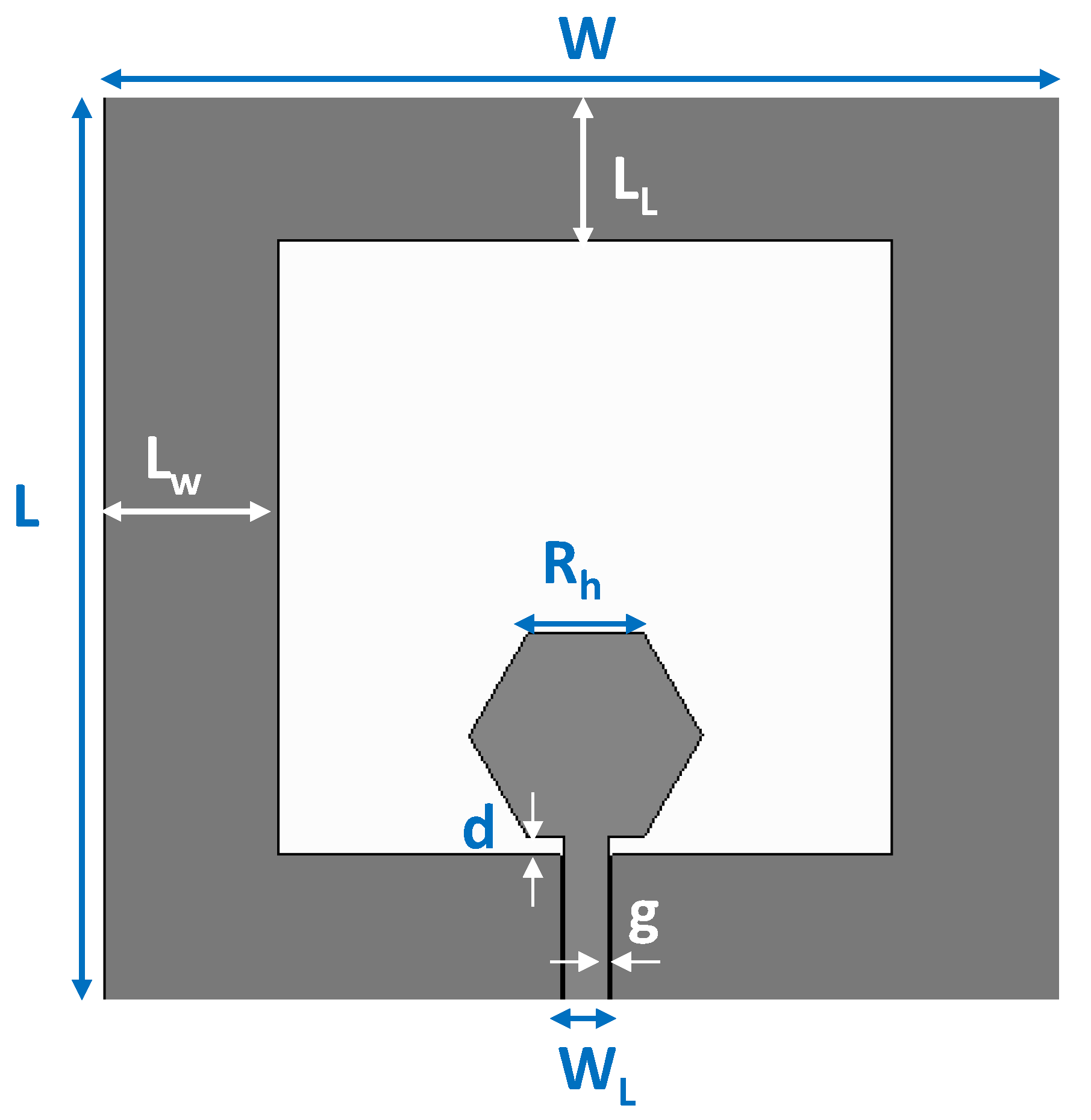
For the design of the feeding line, with a width WL and gap g, not only the 50 Ω impedance but also the dimensions of commercially available connectors have been taken into account.
Figure 2 shows the geometry of the monopole antenna. The radiating slot is defined by surrounding a hexagonal-shaped patch, arising from the CPW-feeding line, with metallic strips connected to both sides of the ground plane.
The dimensions of the antenna have been optimized through FEM-based 3D electromagnetic simulation using HFSS commercial software, so that it is properly matched at the intended IoT bands (around 2.75 GHz and 5.8 GHz) for the three dielectric substrates (ENrG’s Thin E-Strate, Arlon 25N, and polypropylene (PP)). The aim is not so much to design the best possible antenna, but to design a compact antenna that properly covers the intended bands—and to compare the size and performance with the three materials to study the possibilities of the novel ceramic substrate for the antenna’s applications. The dimensions obtained for the optimized antenna design, in terms of impedance matching, based on the different materials are detailed in
Table 2.
A parametric analysis was conducted to optimize the design of the antenna at the intended frequencies of operation for IoT. Increasing W improves the matching in the upper frequency band whereas increasing L does it in the lower band while shifting-down the upper resonance. A higher value of Rh decreases the upper resonance frequency, though if its value is too low there is only one resonance in the intended frequency range. A higher d value improves the matching, especially for the upper band. LW mainly influences the matching of the lower band, whereas LL varies the matching while shifting both frequency bands so that a trade-off has to be adopted.
According to
Table 2, the total size of the optimized CPW-fed slot monopole antenna based on ENrG’s Thin E-Strate is 40.92 cm
2, whereas for both Arlon 25N and PP is 48.3 cm
2. Thus, using the novel Thin E-Strate substrate lead to a 15.28% size reduction. Furthermore, this new substrate is 20 and 11.25 times thinner than Arlon 25N and PP, respectively. Therefore, the antenna on the novel flexible substrate is not only smaller than on the rigid Arlon 25N and the flexible PP, but also much thinner.
3.2. Antenna Matching
From the return loss simulation results shown in
Figure 3, it can be observed that the CPW-fed slot monopole antenna is well matched at the intended IoT bands for the three dielectric substrates under consideration, and for the corresponding dimensions included in
Table 2.
The flexible PP provides better impedance matching than the Arlon 25 N for the lower frequency band around 2.7 GHz, whereas for the upper band around 5.8 GHz, the Arlon 25N renders better matching than the PP. Moreover, the Thin E-Strate allows very good impedance matching for both frequency bands. The antenna based on ENrG’s Thin E-Strate is better-matched than one based on the Arlon 25N for both bands, is at a similar level than for the design based on the PP for the lower band, and much better for the upper band.
The specific operation frequencies and bandwidths obtained in simulation for the CPW-fed slot monopole antenna based on the three dielectrics are indicated in
Table 3. It can be observed that the use of the novel ENrG’s Thin E-Strate makes it possible to obtain the same bandwidth for the lower band than with the PP (27% vs. 23% obtained for the Arlon 25N) and the widest bandwidth for the upper band (51% vs. 47% for the Arlon 25N and 33% for the PP).
These results are very remarkable, taking into consideration that the flexible ENrG’s Thin E-Strate is more than ten-times thinner than the flexible PP and 20-times thinner than the rigid Arlon 25N, while reducing the whole antenna size more than 15% compared to both of them.
Figure 4 shows the surface current distribution of the antenna on ENrG’s Thin E-Strate at three different frequencies: Two operative ones (2.75 GHz and 5.8 GHz) and one at which the antenna is not well matched (1 GHz). At 2.75 GHz, high current levels in the vertical lateral sides (referred as metallic strips in the geometry description) can be observed, which agrees with the parametric analysis concerning L and L
w influence on the matching at this frequency. Moreover, there is only one null at the upper central part of the geometry, reinforcing the statement with regard to L
L influence on the matching. Of course, as expected, there are high currents near the feeding line and the inferior part of the hexagon. At 5.8 GHz, the currents are mainly concentrated in the lower part of the geometry, which agrees with the influence of d (as well as for 2.75 GHz). It is remarkable that there are three nulls: One at the same location as for 2.75 GHz, and two additional ones in the lateral upper sides, which reinforce the idea of W influencing the matching at this frequency and L shifting it downwards. The currents on the hexagon are also remarkable, covering the whole shape with higher value than at the lower frequency, which explains the influence of R
h on the shift of the higher frequency band. It has to be kept in mind that this is a slot type antenna, so that the variation on the slot (achieved through the geometry elements variation) is what counts. Finally, at 1 GHz, the current level is low since the antenna is not operative.
3.3. Radiation Properties of the Antenna
The radiation properties of the CPW-fed slot monopole antenna have been analyzed in simulation for the three substrates under consideration.
Table 4 indicates the results obtained concerning the peak-realized gain G(dB), the directivity D(dB), and the radiation efficiency η(%) for several frequencies included in both the lower and the upper bands.
It can be observed that the antenna behaves in a very similar way for the three dielectrics. The gain and the directivity are slightly higher for the Arlon 25N and the PP in the upper frequency band. For most WLAN and IoT applications, omnidirectional antennas are preferred so that the directivity is not the parameter to be enhanced. However, the radiation efficiency is the key parameter and the challenging one to be preserved when reducing the antenna size. It can be highlighted that with ENrG’s Thin E-Strate, the radiation efficiency is slightly improved for the lower band compared to the Arlon 25N and for the upper band compared to the PP.
The radiation patterns of the CPW-fed slot monopole antenna on ENrG’s Thin E-Strate have been obtained in simulation for the 2.7GHz and 5.8GHz frequencies. The results in both 3D and the corresponding cuts for Phi = 0
° (H-plane) and Phi = 90
° (E-plane) are depicted in
Figure 5. As expected, the antenna exhibits a monopole-like radiation pattern, quite omnidirectional for the H-plane at both frequency bands.
5. Conclusions
In this contribution, an ultra-thin compact flexible CPW-fed slot monopole antenna, suitable for IoT applications around 2.75 GHz and 5.8 GHz, was designed based on ENrG’s Thin E-Strate®.
This novel ceramic dielectric, which electromagnetic characterization was analyzed, provides 20- and 11.25-times thinner antennas compared to Arlon 25N and flexible PP, respectively, while resulting in more than a 15% size reduction.
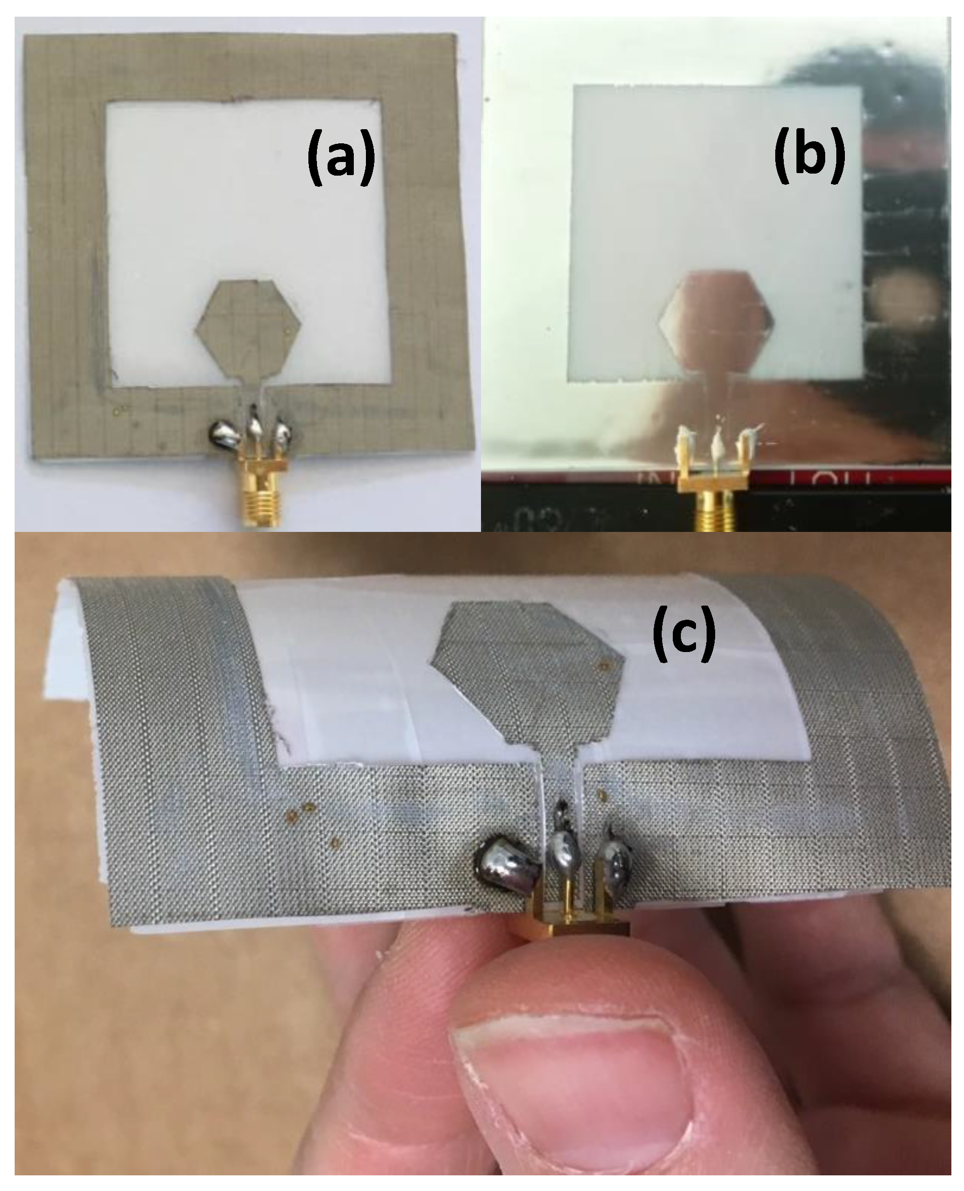
Antenna prototypes on ENrG’s Thin E-Strate were fabricated using two metallization techniques—electrotextile and inkjet printing—and have been subsequently characterized in terms of return losses with proper results.
The prototype on ENrG’s Thin E-Strate showing better results, was compared with one fabricated on Arlon 25N, in terms of radiation properties obtained through measurement in anechoic chamber. The antenna on ENrG’s Thin E-Strate exhibits excellent radiation performance, while concluding that the conventionally used Arlon 25N has no advantages over the novel Zirconia-based material on these aspects.
The authors are currently involved in improving the fabrication on ENrG’s Thin E-Strate using inkjet printing, not only on silver but also on copper, with promising results.

 ,
, 


