Development of an Autonomous Unmanned Aerial Manipulator Based on a Real-Time Oriented-Object Detection Method


Abstract
1. Introduction
2. System Description
2.1. Notation
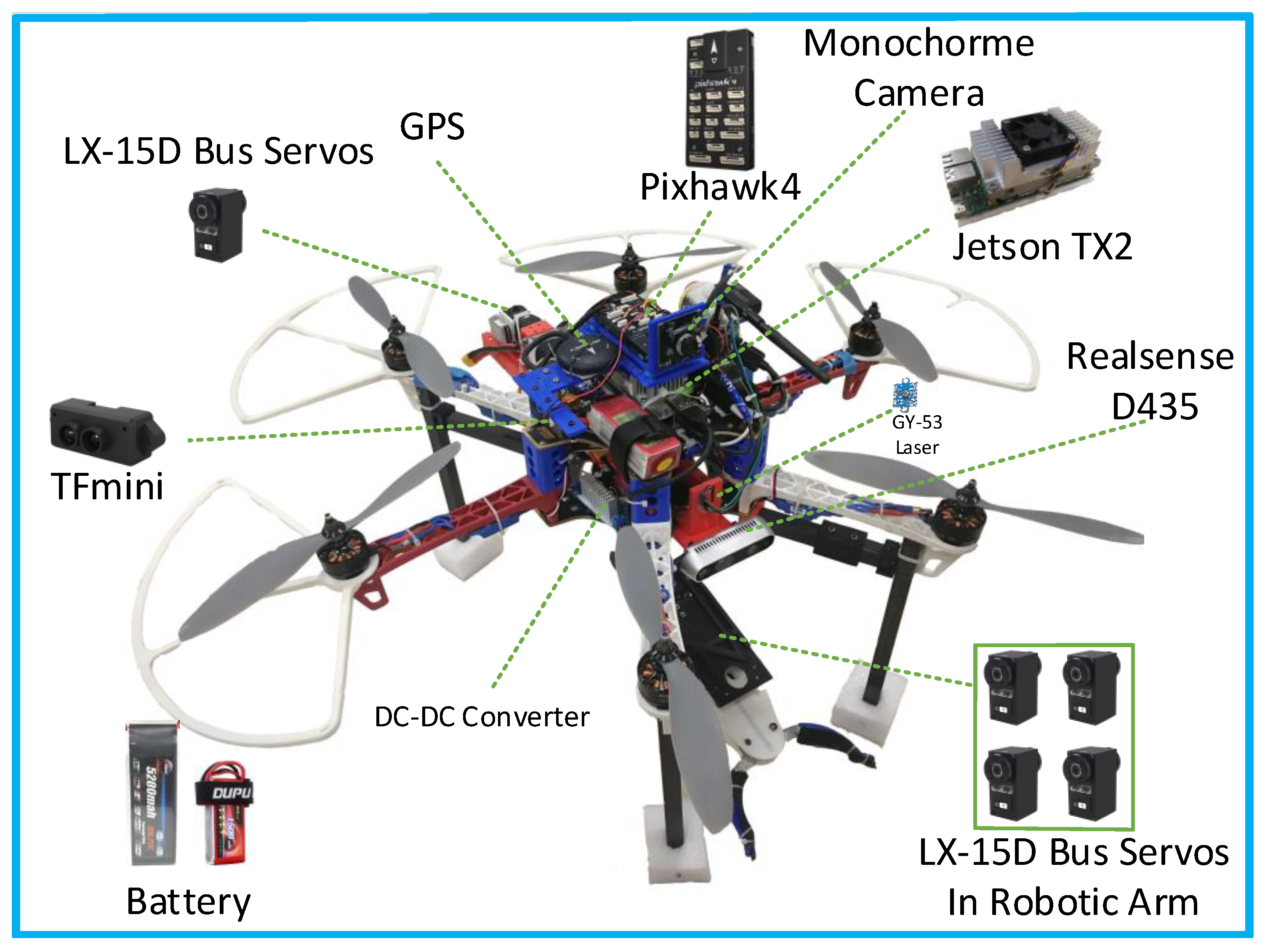
2.2. Hardware
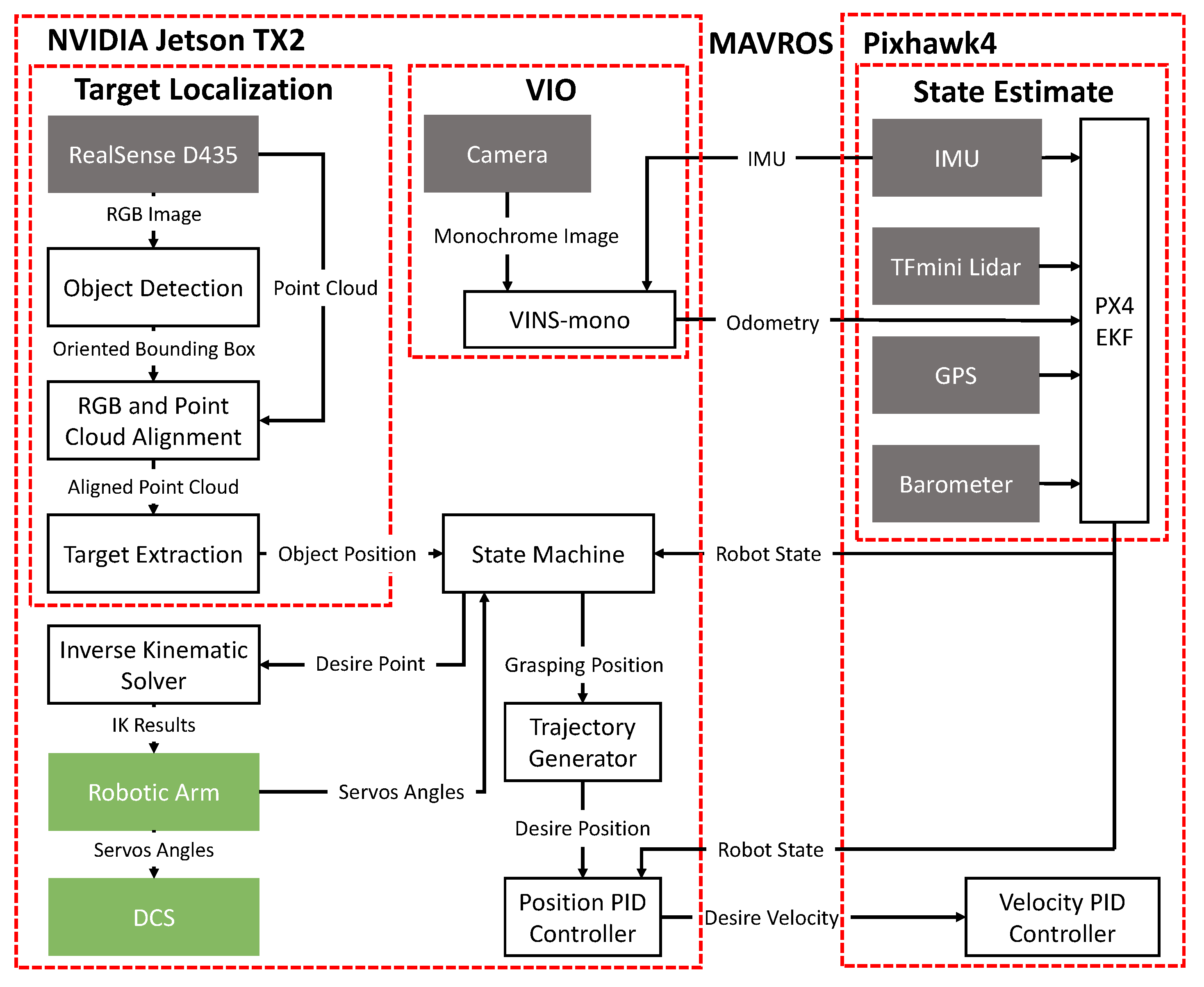
2.3. Software Architecture
2.4. State Estimation
3. Robotic Arm & DCS
3.1. Robotic Arm Motion Planning
3.2. CoG Compensation
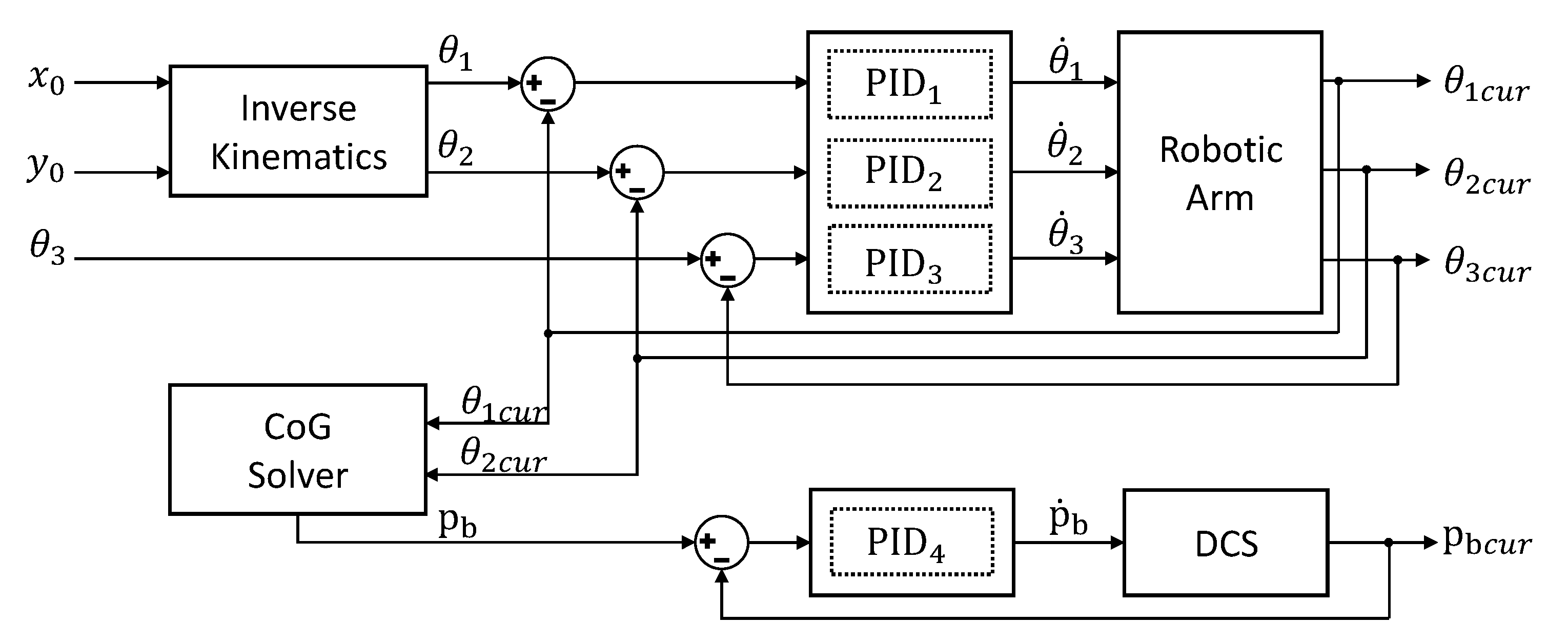
3.3. Control Strategy of Robotic Arm
4. Vision System
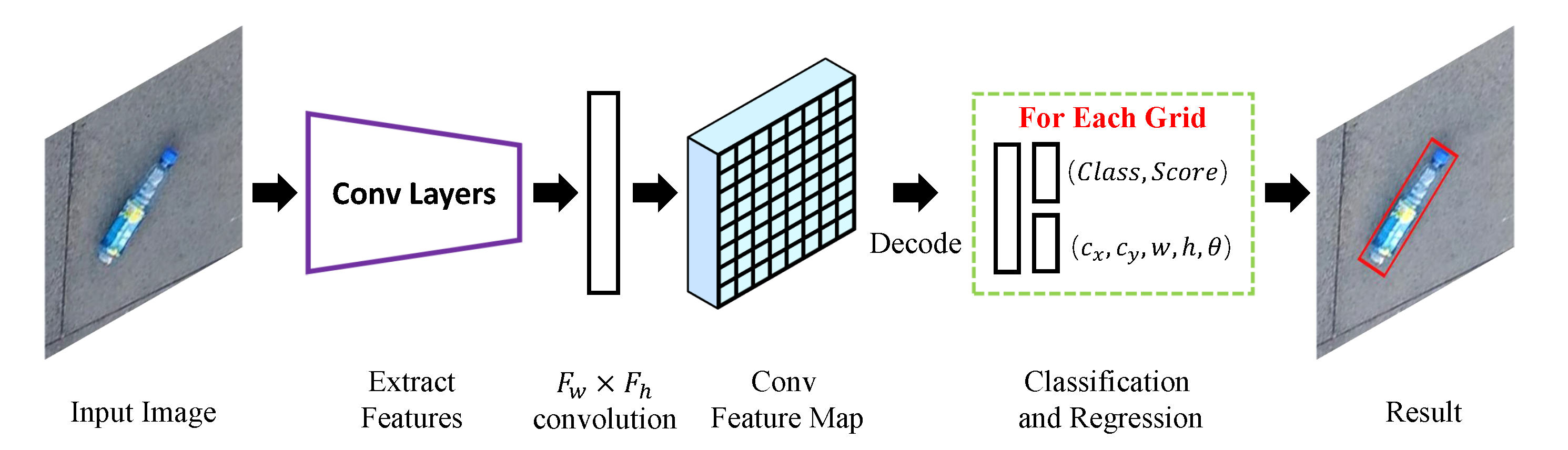
4.1. Network Architecture
4.2. Oriented IoU Computation
4.3. R-Anchors’ Selection
4.4. Object Localization
5. Experiments
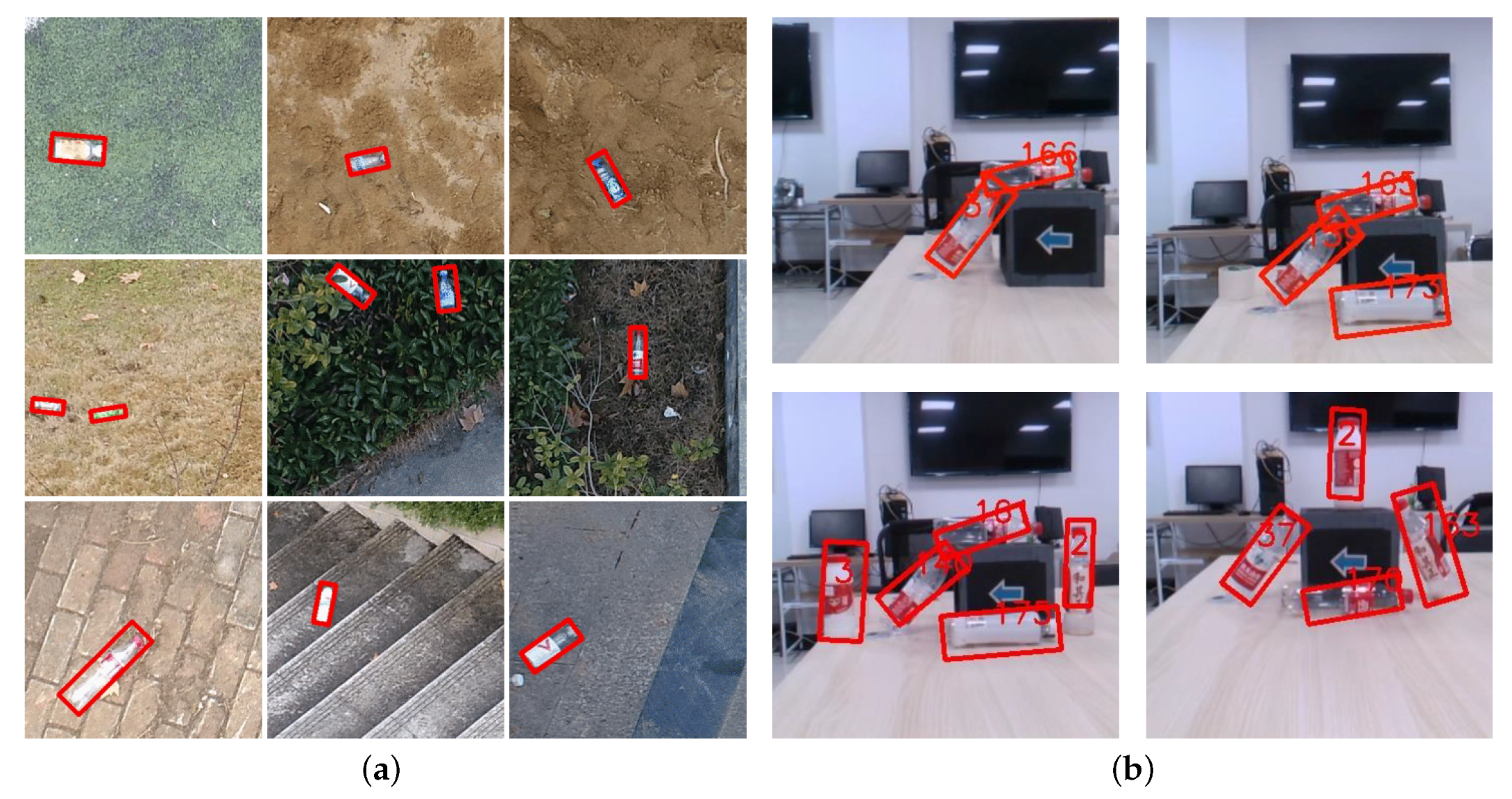
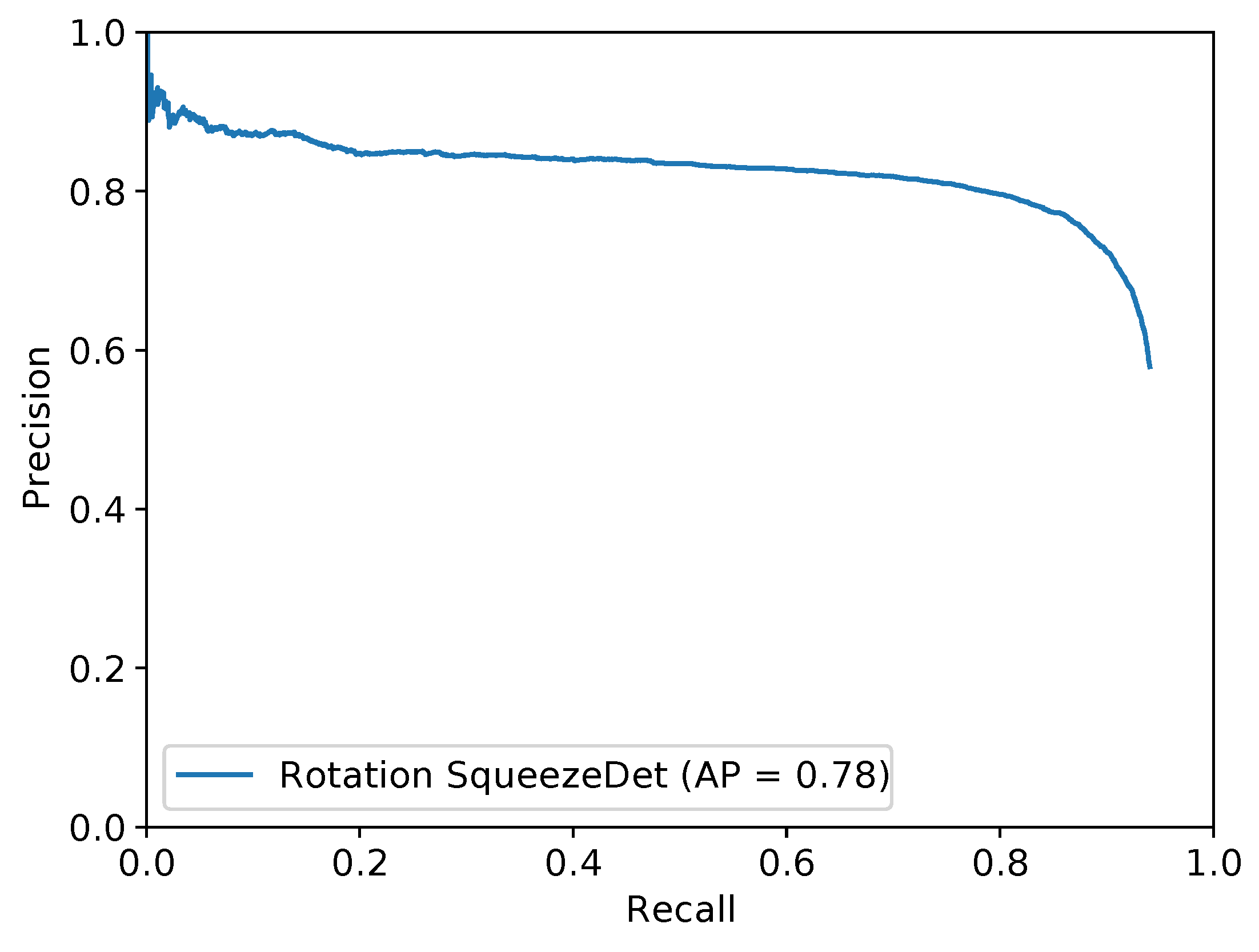
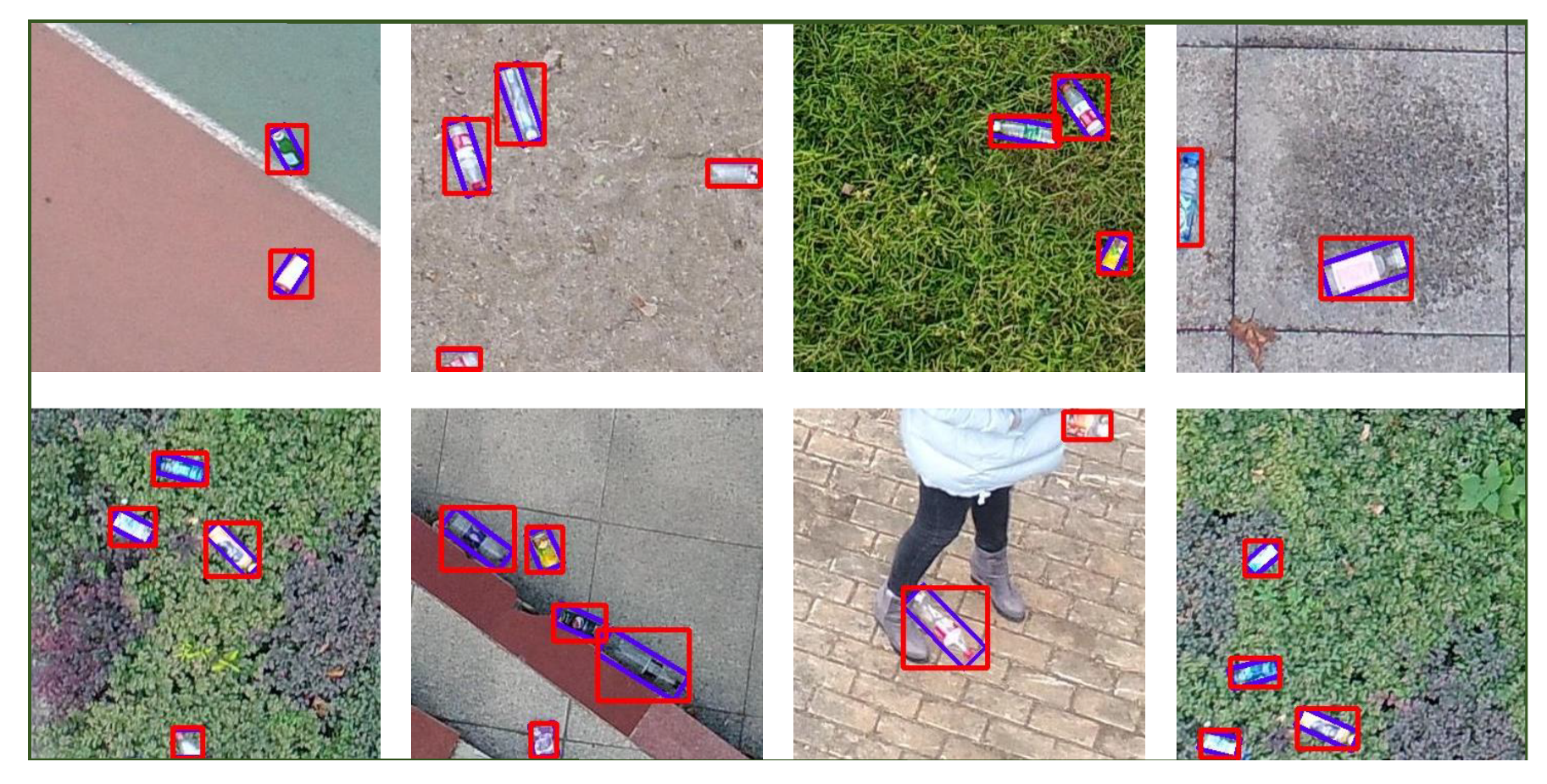
5.1. Vision System Results
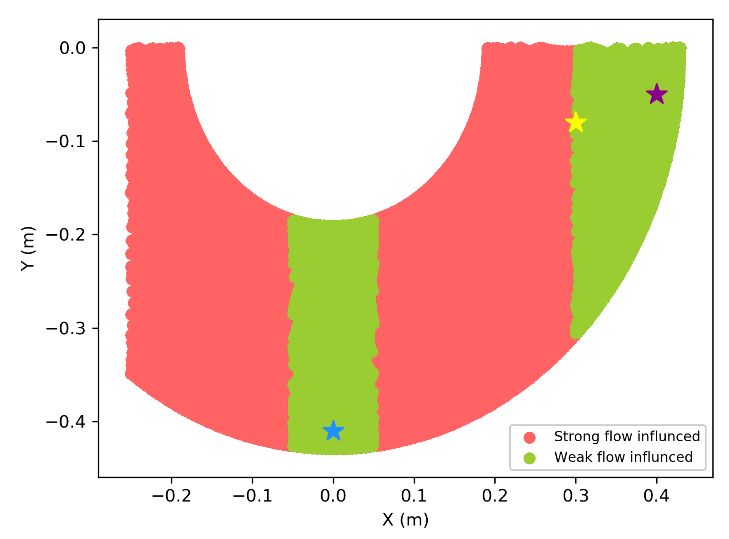
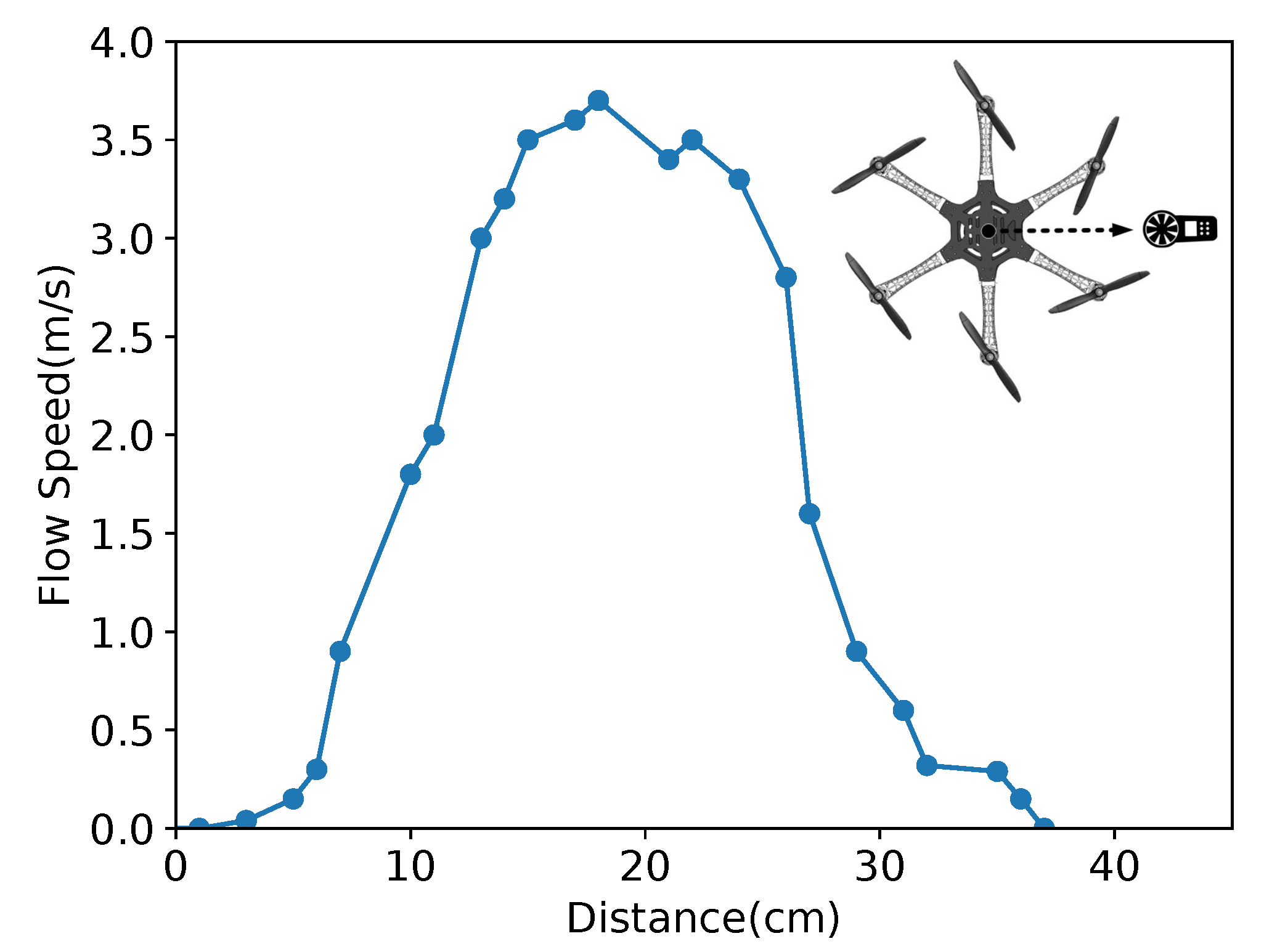
5.2. Flow Distribution Validation
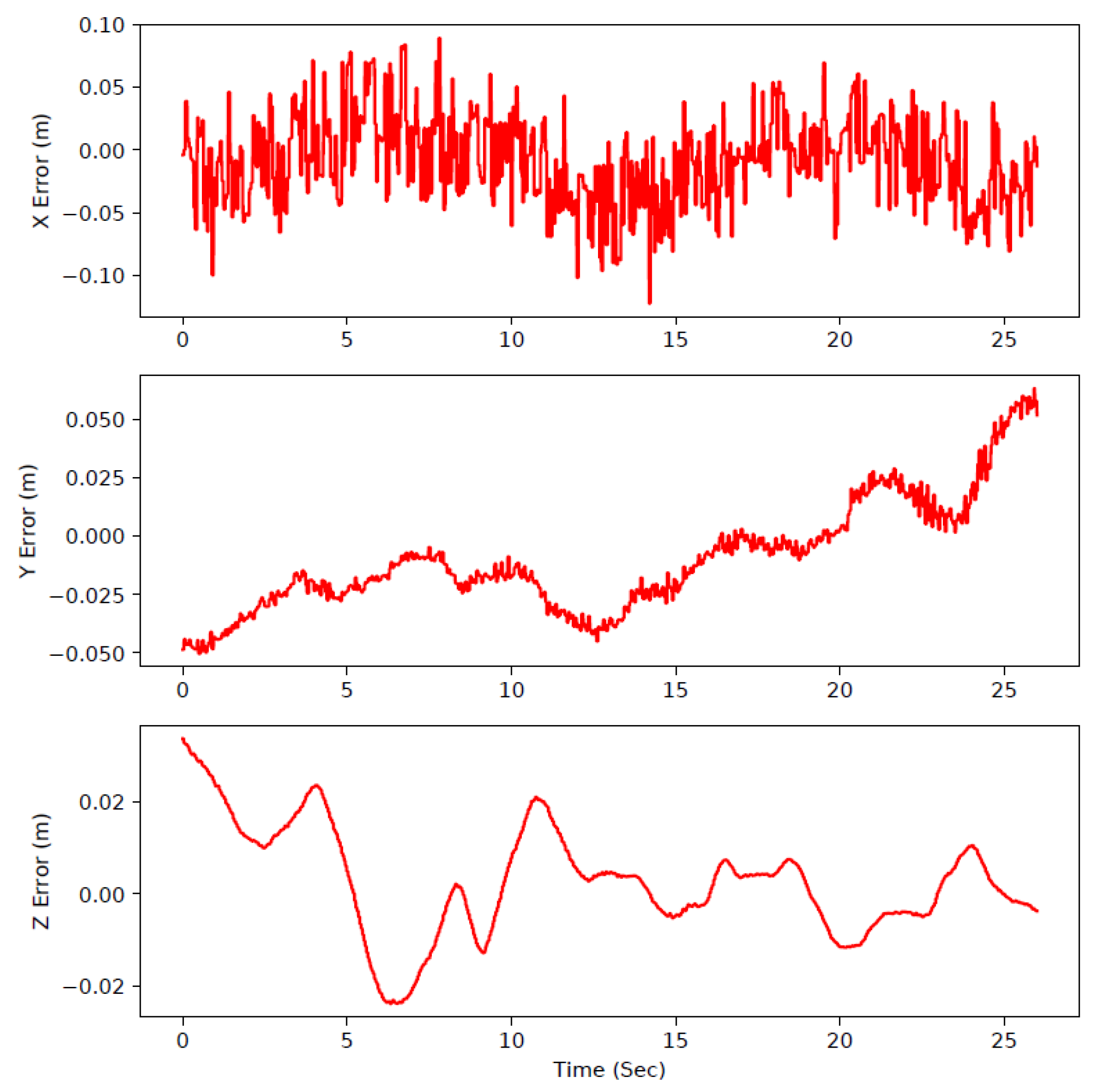
5.3. Aerial Robotic Arm Moving Test
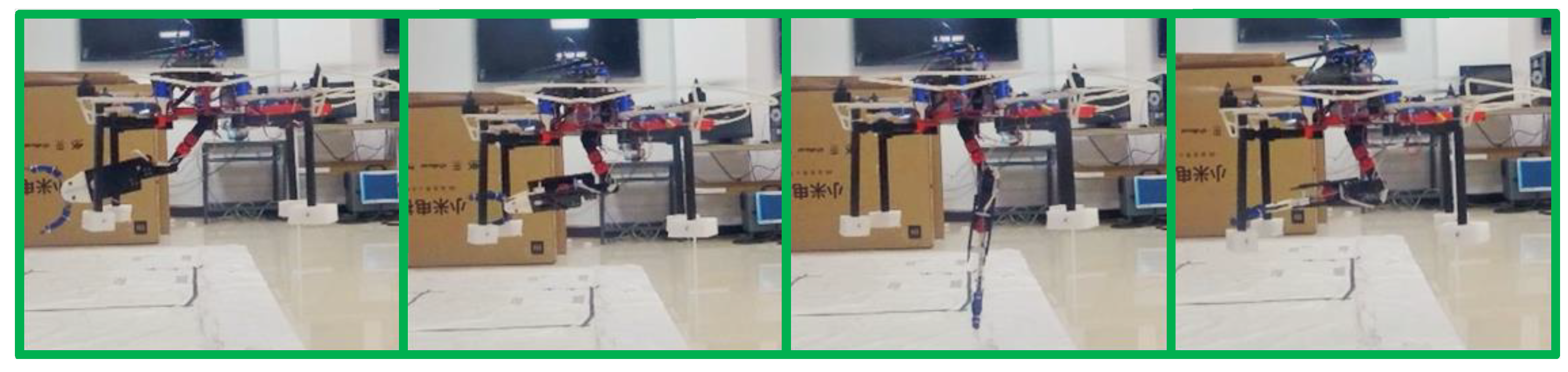
5.4. Autonomous Grasping
6. Conclusions
Author Contributions
Funding
Conflicts of Interest
Abbreviations
| UAM | Unmanned Aerial Manipulator |
| UAMs | Unmanned Aerial Manipulators |
| UAV | Unmanned Aerial Vehicle |
| UAVs | Unmanned Aerial Vehicles |
| 2D | 2-dimension |
| 3D | 3-dimension |
| SLAM | Simultaneous Localization and Mapping |
| YOLO | You Only Look Once |
| PLA | Poly Lactic Acid |
| ESC | Electronic Speed Controller |
| VPIB | Variable Parameter Integral Backstepping |
| IBVS | Image-Based Visual Servo |
| PID | Proportional Integral Derivative |
| ENU | East, North, and Up |
| D-H | Denavit-Hartenberg |
| CoG | Center of Gravity |
| ToF | Time of Flight |
| DoF | Degree of Freedom |
| ROS | Robot Operating Syste |
| VIO | Visual Inertial Odometry |
| EKF | Extended Kalman Filter |
| GPS | Global Positioning System |
| EKF | Extended Kalman Filter |
| IMU | Inertial Measurement Unit |
| FPS | Frames Per Second |
| CFD | Computational Fluid Dynamics |
| IK | Inverse Kinematics |
| RRPN | Rotation Region Proposal Networks |
| RPN | Region Proposal Network |
| RoIs | Region of Interests |
| R-anchors | Rotation anchors |
| IoU | Intersection over Union |
| AP | Average Precision |
| NMS | Non-maximum Suppression |
| CPU | Central Processing Unit |
| GPU | Graphics Processing Unit |
References
- Lendzioch, T.; Langhammer, J.; Jenicek, M. Estimating Snow Depth and Leaf Area Index Based on UAV Digital Photogrammetry. Sensors 2019, 19, 1027. [Google Scholar] [CrossRef]
- Olivares-Mendez, M.A.; Fu, C.; Ludivig, P.; Bissyandé, T.F.; Kannan, S.; Zurad, M.; Annaiyan, A.; Voos, H.; Campoy, P. Towards an Autonomous Vision-Based Unmanned Aerial System against Wildlife Poachers. Sensors 2015, 15, 31362–31391. [Google Scholar] [CrossRef] [PubMed]
- Ruggiero, F.; Lippiello, V.; Ollero, A. Aerial Manipulation: A Literature Review. IEEE Robot. Autom. Lett. 2018, 3, 1957–1964. [Google Scholar] [CrossRef]
- Kim, S.; Choi, S.; Kim, H.J. Aerial manipulation using a quadrotor with a two DOF robotic arm. In Proceedings of the 2013 IEEE/RSJ International Conference on Intelligent Robots and Systems (IROS), Tokyo, Japan, 3–7 November 2013; pp. 4990–4995. [Google Scholar] [CrossRef]
- Korpela, C.; Orsag, M.; Danko, T.; Oh, P. Insertion tasks using an aerial manipulator. In Proceedings of the 2014 IEEE International Conference on Technologies for Practical Robot Applications (TePRA), Woburn, MA, USA, 14–15 April 2014; pp. 1–6. [Google Scholar] [CrossRef]
- Božek, P.; Al Akkad, M.A.; Blištan, P.; Ibrahim, N.I. Navigation control and stability investigation of a mobile robot based on a hexacopter equipped with an integrated manipulator. Int. J. Adv. Robot. Syst. 2017, 14, 1–13. [Google Scholar]
- Arleo, G.; Caccavale, F.; Muscio, G.; Pierri, F. Control of quadrotor aerial vehicles equipped with a robotic arm. In Proceedings of the 21st Mediterranean Conference on Control and Automation (MED), Chania, Greece, 25–28 June 2013; pp. 1174–1180. [Google Scholar]
- Jimenez-Cano, A.; Martin, J.; Heredia, G.; Ollero, A.; Cano, R. Control of an aerial robot with multi-link arm for assembly tasks. In Proceedings of the 2013 IEEE International Conference on Robotics and Automation (ICRA), Karlsruhe, Germany, 6–10 May 2013; pp. 4916–4921. [Google Scholar]
- Ruggiero, F.; Trujillo, M.A.; Cano, R.; Ascorbe, H.; Viguria, A.; Peréz, C.; Lippiello, V.; Ollero, A.; Siciliano, B. A multilayer control for multirotor UAVs equipped with a servo robot arm. In Proceedings of the 2015 IEEE International Conference on Robotics and Automation (ICRA), Seattle, WA, USA, 26–30 May 2015; pp. 4014–4020. [Google Scholar]
- Ohnishi, Y.; Takaki, T.; Aoyama, T.; Ishii, I. Development of a 4-joint 3-DOF robotic arm with anti-reaction force mechanism for a multicopter. In Proceedings of the 2017 IEEE/RSJ International Conference on Intelligent Robots and Systems (IROS), Vancouver, BC, Canada, 24–28 September 2017; pp. 985–991. [Google Scholar] [CrossRef]
- Fabra, F.; Zamora, W.; Masanet, J.; Calafate, C.T.; Cano, J.C.; Manzoni, P. Automatic system supporting multicopter swarms with manual guidance. Comput. Electr. Eng. 2019, 74, 413–428. [Google Scholar] [CrossRef]
- Barka, E.; Kerrache, C.; Hussain, R.; Lagraa, N.; Lakas, A.; Bouk, S. A Trusted Lightweight Communication Strategy for Flying Named Data Networking. Sensors 2018, 18, 2683. [Google Scholar] [CrossRef] [PubMed]
- Kim, S.; Seo, H.; Choi, S.; Kim, H.J. Vision-Guided Aerial Manipulation Using a Multirotor With a Robotic Arm. IEEE/ASME Trans. Mech. 2016, 21, 1912–1923. [Google Scholar] [CrossRef]
- Ramon Soria, P.; Arrue, B.C.; Ollero, A. Detection, location and grasping objects using a stereo sensor on UAV in outdoor environments. Sensors 2017, 17, 103. [Google Scholar] [CrossRef] [PubMed]
- Kanellakis, C.; Terreran, M.; Kominiak, D.; Nikolakopoulos, G. On vision enabled aerial manipulation for multirotors. In Proceedings of the 22nd IEEE International Conference on Emerging Technologies and Factory Automation (ETFA), Limassol, Cyprus, 12–15 September 2017; pp. 1–7. [Google Scholar] [CrossRef]
- Ren, S.; He, K.; Girshick, R.; Sun, J. Faster r-cnn: Towards real-time object detection with region proposal networks. In Proceedings of the Advances in Neural Information Processing Systems 28: 29th Annual Conference on Neural Information Processing Systems 2015, Montreal, QC, Canada, 7–12 December 2015; pp. 91–99. [Google Scholar]
- Redmon, J.; Divvala, S.; Girshick, R.; Farhadi, A. You only look once: Unified, real-time object detection. In Proceedings of the 2016 IEEE Conference on Computer Vision and Pattern Recognition (CVPR), Las Vegas, NV, USA, 26 June–1 July 2016; pp. 779–788. [Google Scholar]
- Wu, B.; Wan, A.; Iandola, F.; Jin, P.H.; Keutzer, K. SqueezeDet: Unified, Small, Low Power Fully Convolutional Neural Networks for Real-Time Object Detection for Autonomous Driving. In Proceedings of the 2017 IEEE Conference on Computer Vision and Pattern Recognition (CVPR), Honolulu, HI, USA, 21–26 July 2017. [Google Scholar]
- Iandola, F.N.; Han, S.; Moskewicz, M.W.; Ashraf, K.; Dally, W.J.; Keutzer, K. SqueezeNet: AlexNet-level accuracy with 50x fewer parameters and <0.5MB model size. arXiv, 2016; arXiv:1602.07360. [Google Scholar]
- Krizhevsky, A.; Sutskever, I.; Hinton, G.E. ImageNet classification with deep convolutional neural networks. In Proceedings of the 25th International Conference on Neural Information Processing Systems, Lake Tahoe, NV, USA, 3–6 December 2012; pp. 1097–1105. [Google Scholar]
- Ma, J.; Shao, W.; Ye, H.; Wang, L.; Wang, H.; Zheng, Y.; Xue, X. Arbitrary-Oriented Scene Text Detection via Rotation Proposals. IEEE Trans. Multimed. 2018, 20, 3111–3122. [Google Scholar] [CrossRef]
- Yang, X.; Sun, H.; Fu, K.; Yang, J.; Sun, X.; Yan, M.; Guo, Z. Automatic ship detection in remote sensing images from google earth of complex scenes based on multiscale rotation dense feature pyramid networks. Remote Sens. 2018, 10, 132. [Google Scholar] [CrossRef]
- Qin, T.; Li, P.; Shen, S. Vins-mono: A robust and versatile monocular visual-inertial state estimator. IEEE Trans. Robot. 2018, 34, 1004–1020. [Google Scholar] [CrossRef]
- Siciliano, B.; Sciavicco, L.; Villani, L.; Oriolo, G. Robotics: Modelling, Planning And Control; Springer: London, UK, 2010. [Google Scholar]
- Quigley, M.; Conley, K.; Gerkey, B.; Faust, J.; Foote, T.; Leibs, J.; Wheeler, R.; Ng, A.Y. ROS: An open-source Robot Operating System. In Proceedings of the ICRA Workshop on Open Source Software, Kobe, Japan, 17 May 2009; Volume 3, p. 5. [Google Scholar]
- Delmerico, J.; Scaramuzza, D. A Benchmark Comparison of Monocular Visual-Inertial Odometry Algorithms for Flying Robots. Memory 2018, 10, 20. [Google Scholar]
- Rehder, J.; Nikolic, J.; Schneider, T.; Hinzmann, T.; Siegwart, R. Extending kalibr: Calibrating the extrinsics of multiple IMUs and of individual axes. In Proceedings of the 2016 IEEE International Conference on Robotics and Automation (ICRA), Stockholm, Sweden, 16–21 May 2016; pp. 4304–4311. [Google Scholar]
- Diaz, P.V.; Yoony, S. High-Fidelity Computational Aerodynamics of Multi-Rotor Unmanned Aerial Vehicles. In Proceedings of the 2018 56th AIAA Aerospace Sciences Meeting, Kissimmee, FL, USA, 8–12 January 2018; p. 1266. [Google Scholar]
- Tripathi, S.; Dane, G.; Kang, B.; Bhaskaran, V.; Nguyen, T. LCDet: Low-Complexity Fully-Convolutional Neural Networks for Object Detection in Embedded Systems. In Proceedings of the 2017 IEEE Conference on Computer Vision and Pattern Recognition Workshops (CVPRW), Honolulu, HI, USA, 21–26 July 2017; pp. 411–420. [Google Scholar] [CrossRef]
- Xie, L.; Ahmad, T.; Jin, L.; Liu, Y.; Zhang, S. A New CNN-Based Method for Multi-Directional Car License Plate Detection. IEEE Trans. Intell. Transp. Syst. 2018, 19, 507–517. [Google Scholar] [CrossRef]
- Redmon, J.; Farhadi, A. YOLO9000: Better, Faster, Stronger. In Proceedings of the 2017 IEEE Conference on Computer Vision and Pattern Recognition (CVPR), Honolulu, HI, USA, 21–26 July 2017; pp. 6517–6525. [Google Scholar]
- Wang, J.; Guo, W.; Pan, T.; Yu, H.; Duan, L.; Yang, W. Bottle Detection in the Wild Using Low-Altitude Unmanned Aerial Vehicles. In Proceedings of the 2018 21st International Conference on Information Fusion (FUSION), Cambridge, UK, 10–13 July 2018; pp. 439–444. [Google Scholar] [CrossRef]
- Abadi, M.; Barham, P.; Chen, J.; Chen, Z.; Davis, A.; Dean, J.; Devin, M.; Ghemawat, S.; Irving, G.; Isard, M.; et al. Tensorflow: A system for large-scale machine learning. In Proceedings of the 12th USENIX Symposium on Operating Systems Design and Implementation (OSDI), Savannah, GA, USA, 2–4 November 2016; Volume 16, pp. 265–283. [Google Scholar]


| Laptop | Server | Jetson TX2 | |
|---|---|---|---|
| Central Processing Unit (CPU) | i7-6700HQ @ 2.6 GHz | E5-2620 V4 @ 2.10 GHz | Cortex-A57 @ 2 GHz |
| Graphics Processing Unit (GPU) | GTX 960M | GTX Titan Xp | 256-core Pascal |
| Laptop | Server | Jetson TX2 | |
|---|---|---|---|
| Model Processing Time (s) | 0.017 | 0.005 | 0.0035 |
| NMS Processing Time (s) | 0.003 | 0.004 | 0.006 |
| Overall Processing Time (s) | 0.020 | 0.009 | 0.041 |
| Overall FPS | 50 | 111 | 24 |
© 2019 by the authors. Licensee MDPI, Basel, Switzerland. This article is an open access article distributed under the terms and conditions of the Creative Commons Attribution (CC BY) license (http://creativecommons.org/licenses/by/4.0/).
Share and Cite
Lin, S.; Wang, J.; Peng, R.; Yang, W. Development of an Autonomous Unmanned Aerial Manipulator Based on a Real-Time Oriented-Object Detection Method. Sensors 2019, 19, 2396. https://doi.org/10.3390/s19102396
Lin S, Wang J, Peng R, Yang W. Development of an Autonomous Unmanned Aerial Manipulator Based on a Real-Time Oriented-Object Detection Method. Sensors. 2019; 19(10):2396. https://doi.org/10.3390/s19102396
Chicago/Turabian StyleLin, Shijie, Jinwang Wang, Rui Peng, and Wen Yang. 2019. "Development of an Autonomous Unmanned Aerial Manipulator Based on a Real-Time Oriented-Object Detection Method" Sensors 19, no. 10: 2396. https://doi.org/10.3390/s19102396
APA StyleLin, S., Wang, J., Peng, R., & Yang, W. (2019). Development of an Autonomous Unmanned Aerial Manipulator Based on a Real-Time Oriented-Object Detection Method. Sensors, 19(10), 2396. https://doi.org/10.3390/s19102396