SmartFire: Intelligent Platform for Monitoring Fire Extinguishers and Their Building Environment


Abstract
1. Introduction
- Class A: Fires that involve solid fuels such as wood, cardboard, plastic, etc.
- Class B: Fires that involve liquid fuels such as oil, gasoline or paint.
- Class C: Fires that involve gas fuels such as butane, propane or city gas.
- Class D: Fires of this type are the rarest, the fuel is a metal, and the burning metals are magnesium, sodium or aluminium powder.
- Water: Suitable for Type A fires always in places where there is no electricity. Water is not suitable for fires involving liquid fuels such as gasoline or oil because it is denser than those liquids; as a result, the fuel would remain on top of the water and it would not be possible to extinguish the fire.
- Water spray: Ideal for extinguishing Type A fires and suitable for Type B fires. They should never be used in the presence of electric current as water could cause electrocution. This type of fire extinguisher is good outside of homes where there is no electrical risk, such as gardens, barbecues, etc.
- Foam: Ideal for Type A and B fires; we have all seen firefighters spray foam at emergency drills. As with the previous one, it is dangerous in the presence of electricity.
- Dust: It is the most common type and is used in any building. It is suitable for fires of Types A, B and C. It is powdery so it can be used in the presence of electricity. It is the most recommended extinguisher for houses, offices or any other type of building.
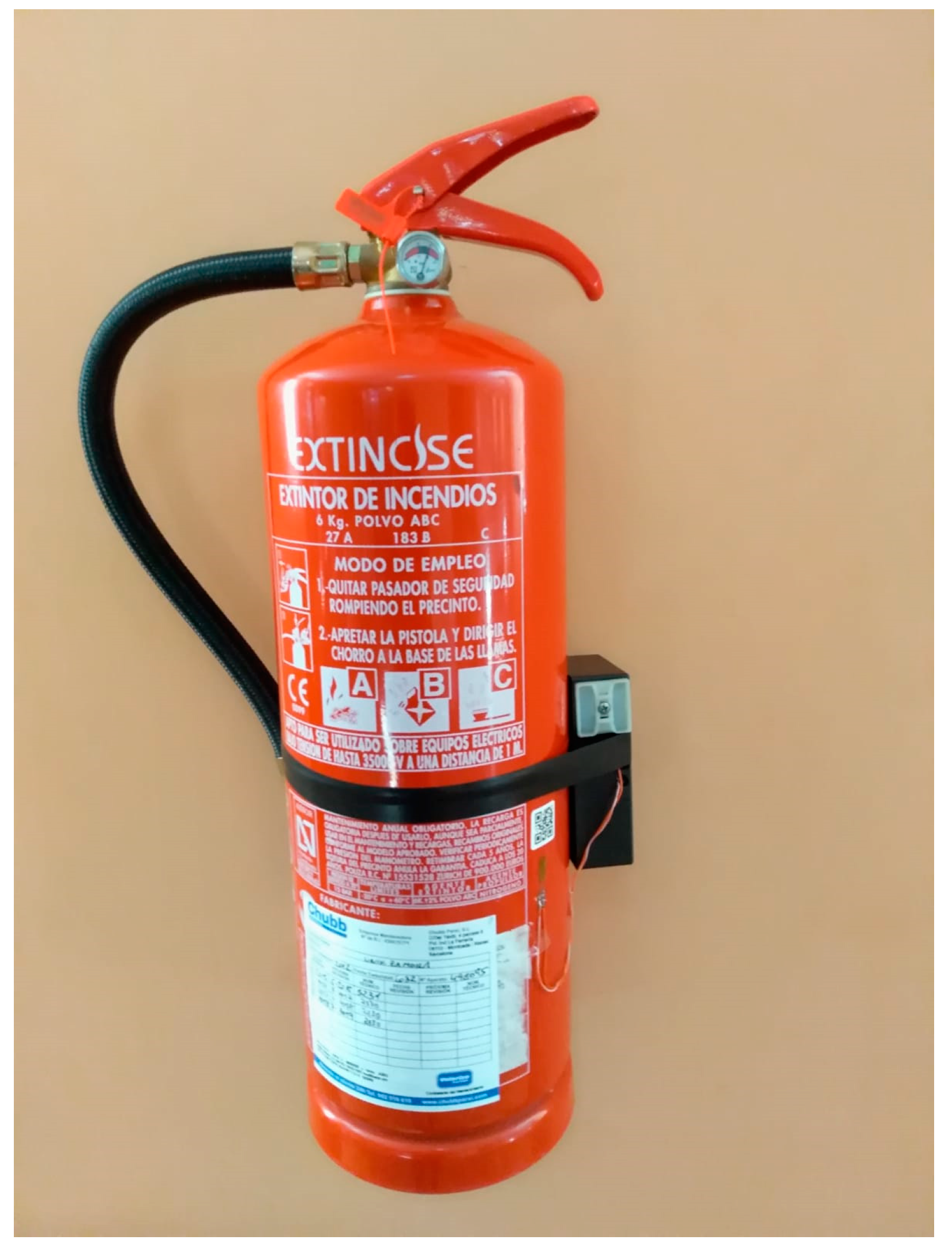
- CO extinguishers: CO is a gas and thus cannot conduct electricity. This type of fire extinguisher is suitable for fires of Types A, B and C. It is usually used in the presence of delicate elements where other types of extinguishers would damage the objects. If we use a standard fire extinguisher in a laboratory, for example, the foam or powder could damage expensive machines and equipment. Thus, CO extinguishers are ideal for this type of environments. Although they are the most versatile of all available extinguishers, they are also the most sensitive ones; changes in temperature can affect them considerably. Given that they do not have a manometer, it is impossible to know their pressure in real time, thus manual inspection is necessary.
2. Related Work
2.1. Proposals with SmartFire Sub-Objectives
2.2. Algorithm for Calculating the Pressure of a Fire Extinguisher
- , the tangential tension, goes in the tangent direction to the circumference. It is the highest of all and increases the perimeter of the cylinder, as a result of the level of deformations, the wall of the cylinder separates along its generator.
- , the radial stress goes in the direction of the radius at the deformation level, making the radius increase in length. It is the smallest of them all.
- , the stress in the direction z makes the cylinder increase in length, at the deformation level it is as if the cylinder were pulled at the ends and stretched.
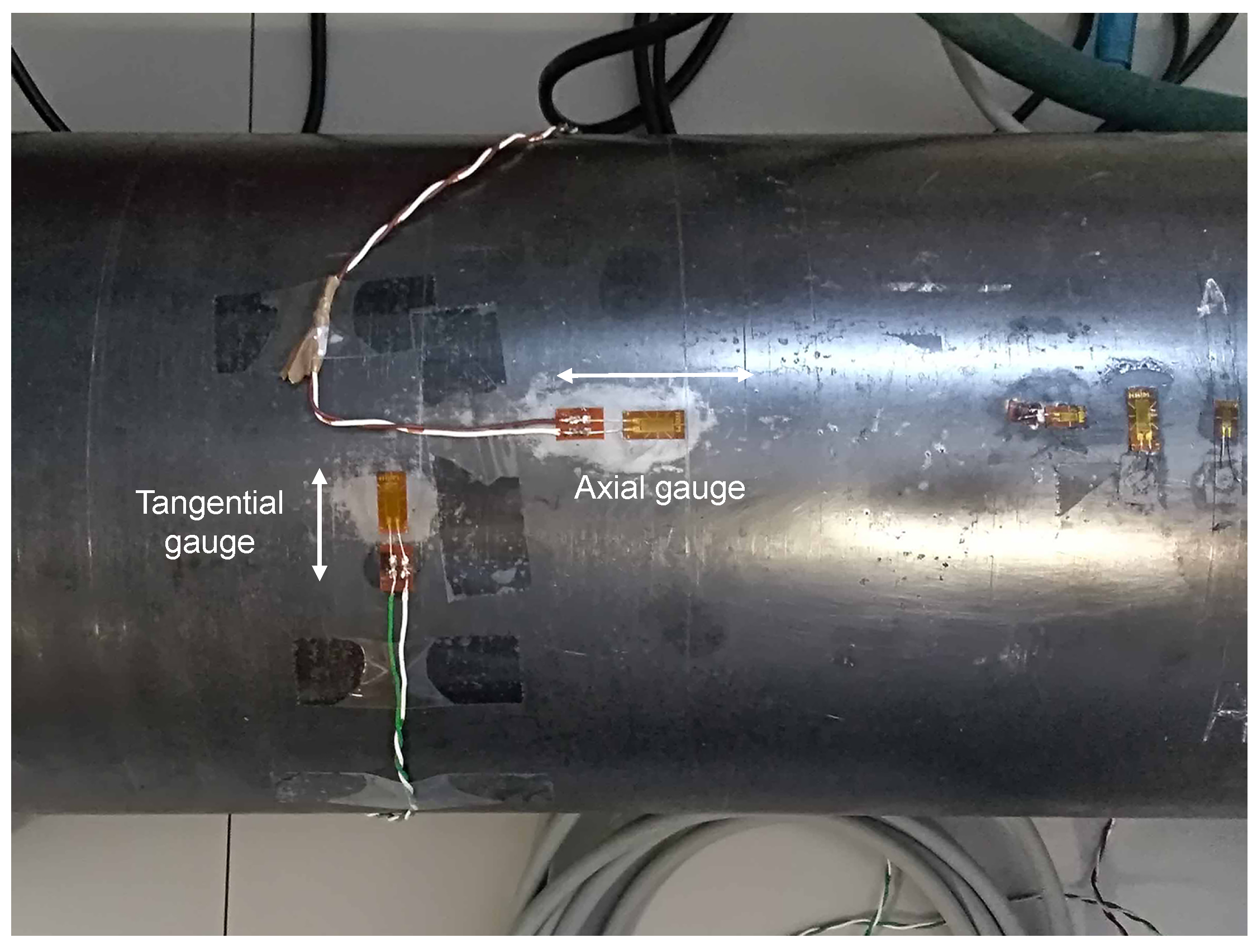
- Thin wall, . In this case, the effect of the thickness is not considered, hence the radial stress () is not taken into account, since it is assumed that the tangential stress () is much larger than the radial stress, which is therefore ignored; the expressions for these stresses [20] are:Tangential stress:Axial stress:Radial stress:These expressions relate internal pressure (P), radius (r) and thickness (t). For the case of the radius, we assume (since thickness is not considered) that both internal and external radii are equal (). Some authors use the mean radius (), which is more accurate.In our case, what we can measure are deformations and not stresses, but through Hooke’s Law [22], which relates tensions and deformations (Equations (5) and (6)) within the linear elastic regime, it is possible to relate the deformation caused by the internal pressure of the gauge because our extinguisher works in this regime.The linear modulus of elasticity (E) is a known characteristic of the material, and is the deformation measured with the gauge, where the subscripts ij indicate the direction in which the deformation occurs.In radial systems, the spatial directions x,y,z are replaced by the radial direction (r), tangential () and z is maintained.The objective of this work was to relate the deformation () with the pressure (P) that it produces; we can relate the values of P with since we know the stress values as functions of the pressure (Equations (1) and (2)) and the value of the deformation () is obtained directly from the gauge. Depending on how the gauge is positioned on the container, it is measured. If the gauge is positioned in the axial direction, the value of is measured and if it is placed tangentially, is obtained.Then the value of the tangential stress (Equation (1)) is introduced in Equation (5); thus, via algebra, we can obtain the internal pressure of the vessel (Equation (6)) since it presents the relation P vs. according to known geometrical parameters and material properties, in this case, the Young’s modulus (E), and the Poisson’s ratio (), which is a parameter of the material and is provided by the manufacturer or obtained through mechanical test. We operate in the same way to obtain the relationship between P and (Equation (7)). In thin wall cases, the radial direction deformation value is ignored, and the gauge cannot be placed in this direction.A large diameter fire extinguisher with a common pressurization (13 bar) is a thin-walled type of fire extinguisher (wheeled extinguisher and extinguishing tanks). In Equation (5), the values measured by the gauge in tangential direction together with Equation (1) are replaced by Equation (6). Similarly, we operate in the z (axial) direction, providing Equation (7), which is the expression to be used in metal containers, since in the radial direction the deformation value is ignored and the gauge cannot be placed.Measurement of the deformation in tangential direction:Measurement of axial deformation:Most of the portable devices are pressurized to 13 bar and their diameters are larger than the thickness (especially in wheeled extinguisher and extinguishing tanks) with the aim of optimizing the volume, thus thin wall is the most common situation, except the CO devices due to the high pressure.
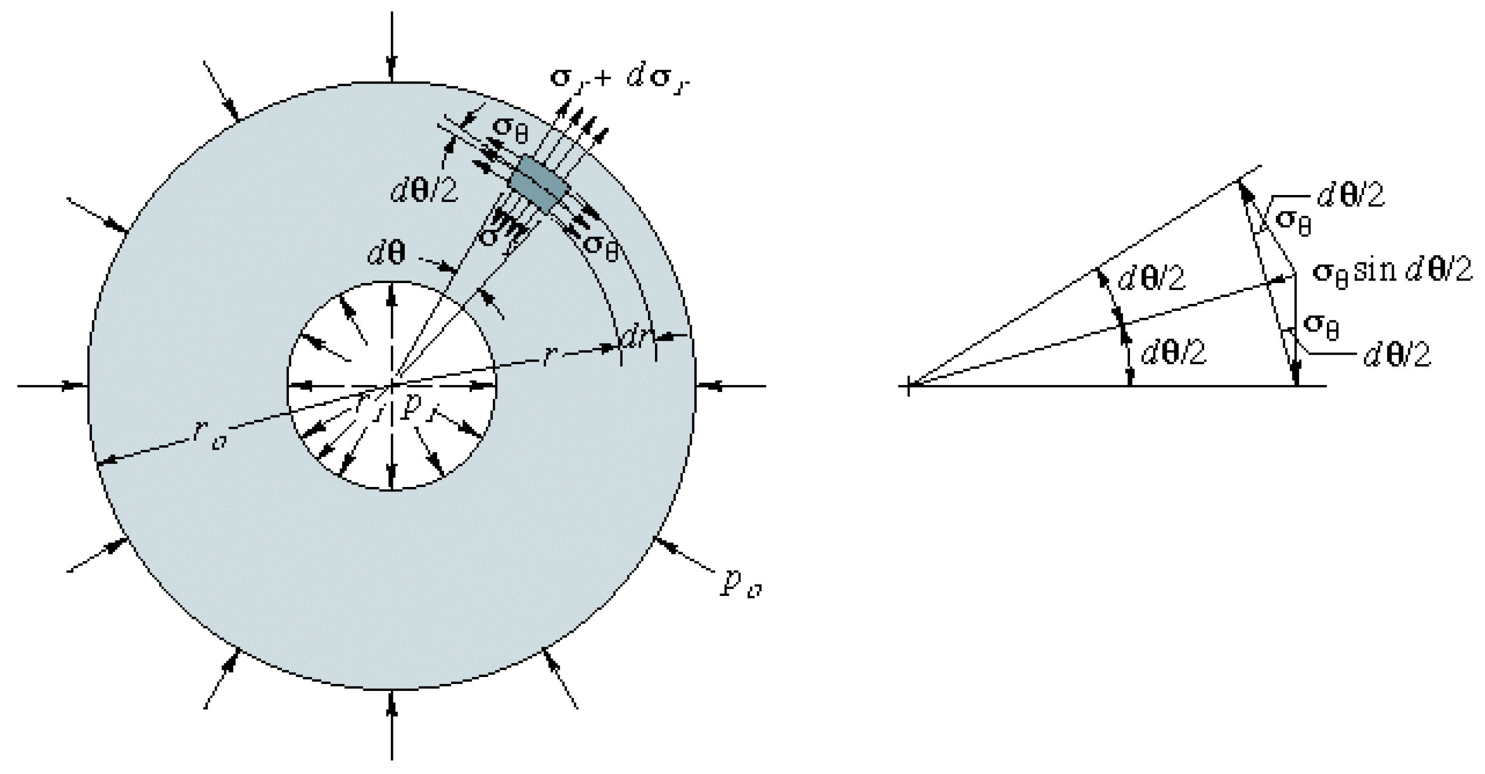
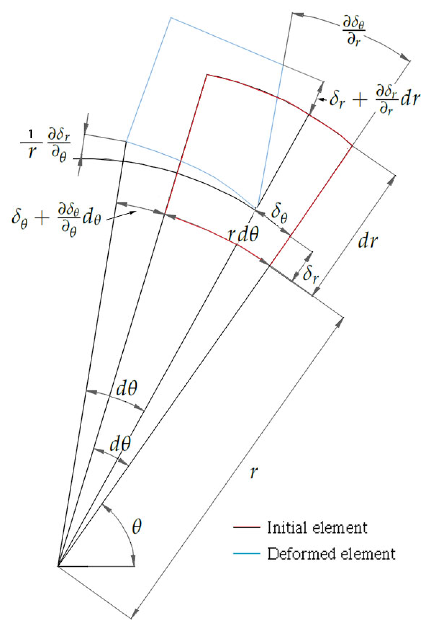
- Thick wall, In this case, the idea is the same, but the formulation is more complex because it is not possible to apply the simplification of negligible thickness in the equations, as it does have an influence here. In Figure 1, we see that the internal pressure generates a series of stresses that will deform the material, as shown in Figure 2. In Figure 2, we can see an undeformed and a deformed element, where the value of the deformation can be calculated by applying finite differences in such a way that we can obtain the value of the deformation according to the displacements.Equations (8) and (9) allow relating deformations to stress, and are fundamental equations exposed in the Fundamentals of Machine Elements deformation theory [23]. These equations are used in the following steps for the calculation of pressure.Here, again, our goal is to calculate pressure as a function of deformation. We know that pressure generates stresses that in turn generate deformations. Now, we reverse this logic and obtain the stresses from the deformations. This is achieved by applying Hooke’s law (Equation (4)) where the expressions of both radial (Equation (10)) and tangential (Equation (11)) deformations are functions of both radial and tangential stresses.By equating Equations (8) and (10), we obtain Equation (12), and, by equating Equations (9) and (11), we obtain Equation (13).Equations (12) and (13) form a system of two equations and three unknowns, where, if we apply the criterion of equilibrium to the system of forces that generate the tensions (Figure 1), we obtain Equation (14), such that this equation complements the previous system and it can be solved as a compatible and determined system.If we now substitute Equation (14) into Equation (12) and equate it to Equation (15), by substituting and operating, we obtain the relationship in Equation (16), which can also be expressed as Equation (17).Integrating once:Re-integrating and simplifying:Integrating once again:Applying the boundary conditions to Equation (20), for a general pressurization case where we would have to:By operating, we obtain the value of the constants:such that, by substituting the value of the constants in Equation (20) and simplifying, we obtain:The tangential stress is provided by Equation (14), where by substituting the value of the radial stress (Equation (25)) and the value of its derivative with respect to r (Equation (26))For this particular case, where << , it is assumed that = 0, substituting in Equations (25) and (27) would give particular stress values.Finally, to return to Equation (11), we can relate the deformation with the pressureSince the strain gauge is placed on the outside radius, the expression is reduced to:Since both the material and the geometry are known, by placing a gauge on the outside of the fire extinguisher in the tangential (circumferential) direction, we can determine the value of the internal pressure in the vessel (fire extinguisher).
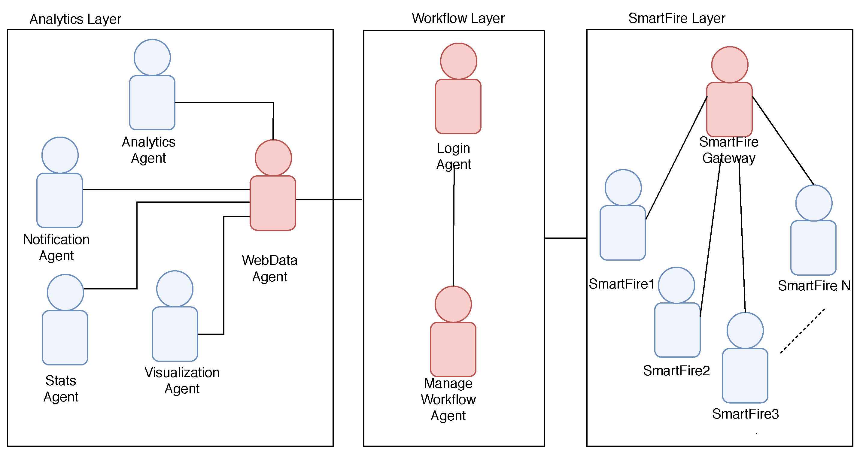
2.3. Agent Based Monitoring Platform
3. SmartFire Platform
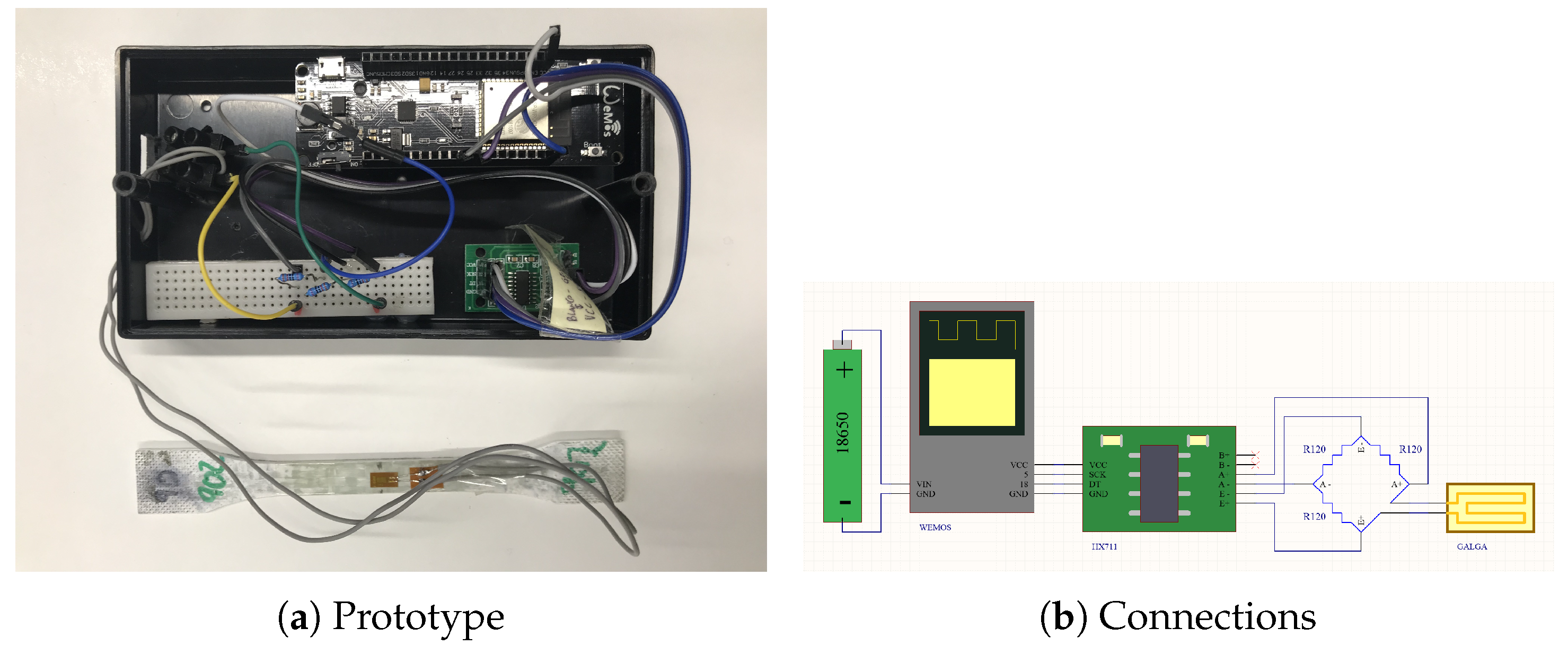
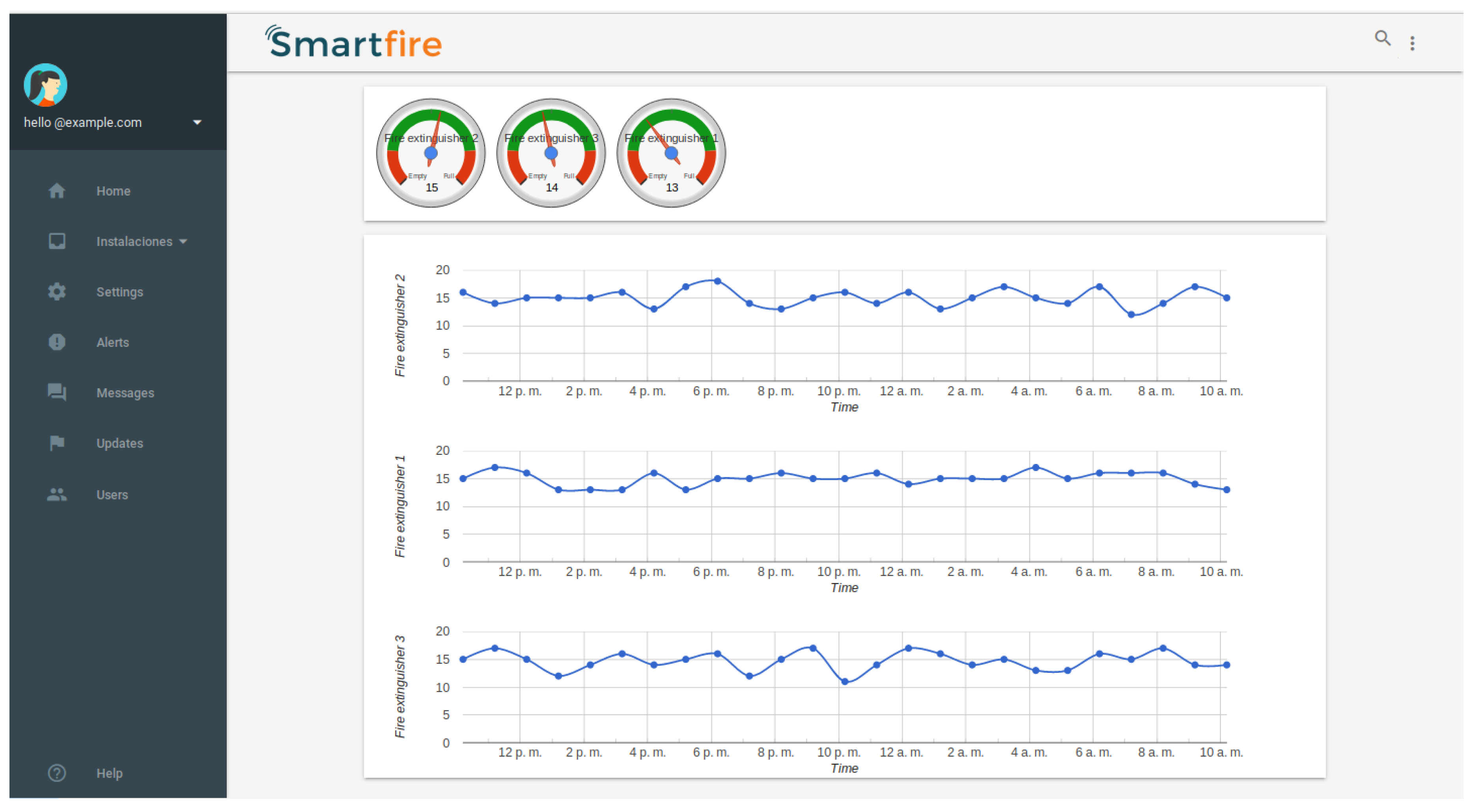
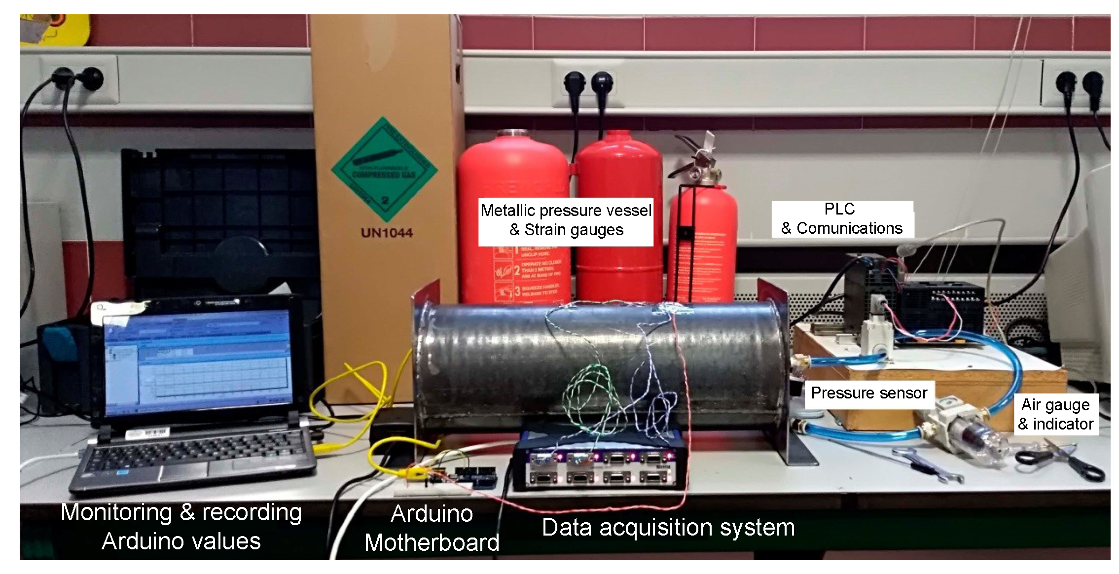
3.1. Prototype Overview
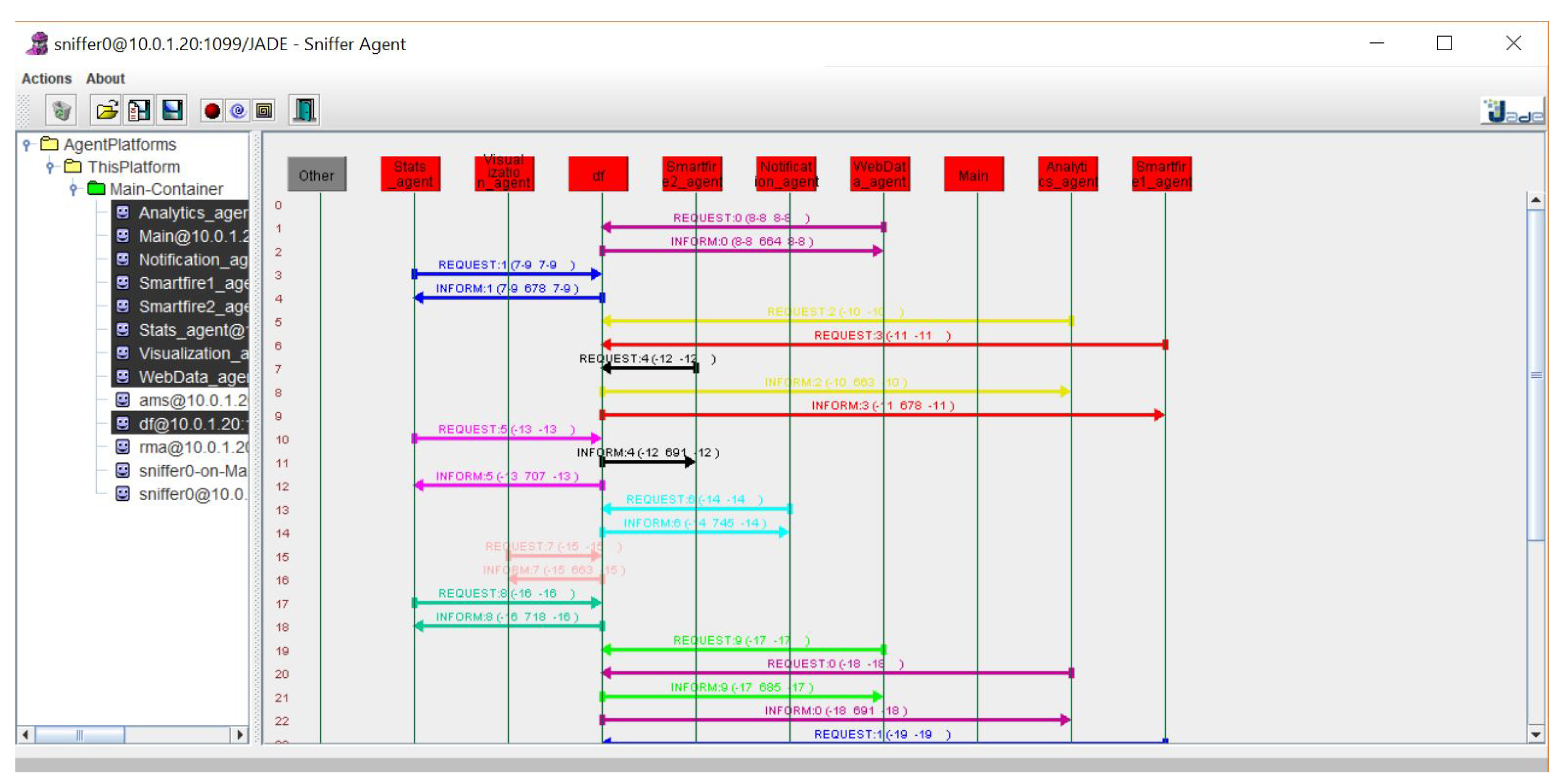
3.2. Soft Agent Platform
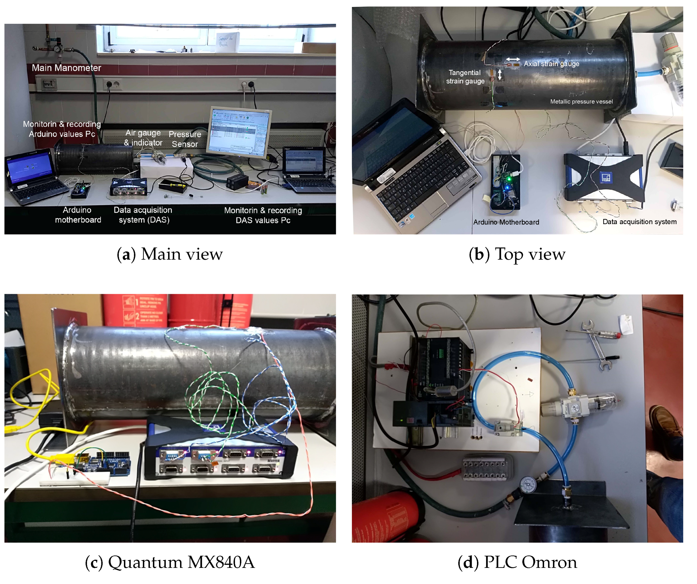
4. Case Study: Laboratory Validation
5. Results
6. Conclusions and Future Work
Author Contributions
Funding
Conflicts of Interest
References
- Rubadiri, L.; Ndumu, D.T.; Roberts, J.P. Predicting the evacuation capability of mobility-impaired occupants. Fire Technol. 1997, 33, 32–53. [Google Scholar] [CrossRef]
- Xing, E.; Jin, J.; Zhang, Z.; Pan, R.; Li, Q.; Zheng, J. Simulation on flow rate characteristics of gas fire extinguishing agent with expansion nozzle based on AMESim. In Proceedings of the CSAA/IET International Conference on Aircraft Utility Systems (AUS 2018), Guiyang, China, 19–22 June 2018. [Google Scholar]
- Wu, Y.; Zhuang, H.; Yu, P. Numerical Simulation of Gas-Solid Two-Phase Jet in a Non-pressure-accumulated and Handheld Fire Extinguisher. In Proceedings of the 2018 3rd International Conference on Modelling, Simulation and Applied Mathematics (MSAM 2018), Shanghai, China, 22–23 July 2018. [Google Scholar]
- Schroll, R.C. Industrial Fire Protection Handbook; CRC Press: Boca Raton, FL, USA, 2016. [Google Scholar]
- Cournoyer, M.E.; Waked, R.R.; Granzow, H.N.; Gubernatis, D.C. Verification study of an emerging fire suppression system. J. Chem. Health Saf. 2016, 23, 26–32. [Google Scholar] [CrossRef]
- Lim, Y.S.; Lim, S.; Choi, J.; Cho, S.; Kim, C.K.; Hu, Y.W.L.H.; Zhang, H.; Hu, H.; Xu, B.; Li, J.; et al. A fire detection and rescue support framework with wireless sensor networks. In Proceedings of the 2007 International Conference on Convergence Information Technology (ICCIT 2007), Gyeongju, Korea, 21–23 November 2007; pp. 135–138. [Google Scholar]
- JiJi, R.D.; Hammond, M.H.; Williams, F.W.; Rose-Pehrsson, S.L. Multivariate statistical process control for continuous monitoring of networked early warning fire detection (EWFD) systems. Sens. Actuators B Chem. 2003, 93, 107–116. [Google Scholar] [CrossRef]
- Guan, Y.X.; Fang, Z.; Wang, T.R. Fire Risk Assessment and Daily Maintenance Management of Cultural Relic Buildings Based on ZigBee Technology. Procedia Eng. 2018, 211, 192–198. [Google Scholar] [CrossRef]
- Purser, D.A.; Bensilum, M. Quantification of behaviour for engineering design standards and escape time calculations. Saf. Sci. 2001, 38, 157–182. [Google Scholar] [CrossRef]
- Pires, T.T. An approach for modeling human cognitive behavior in evacuation models. Fire Saf. J. 2005, 40, 177–189. [Google Scholar] [CrossRef]
- Hu, H.; Wang, G.; Zhang, Q.; Wang, J.; Fang, J.; Zhang, Y. Design wireless multi-sensor fire detection and alarm system based on ARM. In Proceedings of the 2009 9th International Conference on Electronic Measurement & Instruments, Beijing, China, 16–19 August 2009; pp. 3–285. [Google Scholar]
- Lee, K.C.; Lee, H.H. Network-based fire-detection system via controller area network for smart home automation. IEEE Trans. Consum. Electron. 2004, 50, 1093–1100. [Google Scholar]
- Zick, L.; Carlson, C. Strain gage technique employed in studying propane tank stressesunder service conditions. Steel 1948, 86, 88. [Google Scholar]
- Choi, Y.; Ahn, J.; You, H.; Jo, C.; Cho, Y.; Noh, Y.; Chang, D.; Chung, H.; Bergan, P.G. Numerical and experimental study of a plate-stiffened prismatic pressure vessel. Ocean Eng. 2018, 164, 367–376. [Google Scholar] [CrossRef]
- Diego, F.J.; Esteban, B.; Merello, P. Design of a hybrid (wired/wireless) acquisition data system for monitoring of cultural heritage physical parameters in smart cities. Sensors 2015, 15, 7246–7266. [Google Scholar] [CrossRef] [PubMed]
- Park, K.H.; Lee, Y.S.; Kim, S.J.; Kim, Y.H.; Park, B.C. Computer Vision-based Pressure Gauge Measurement for Fire Extinguisher Inspection. In Proceedings of the 2017 International Conference on Platform Technology and Service (PlatCon), Busan, Korea, 13–15 February 2017; pp. 1–4. [Google Scholar]
- Jin, J.M.; An, F.L.; Shou, Y.; Pan, R.M.; Xuan, Y.; Li, Q.W. Simulation on Release Characteristics of the Gas Extinguishing Agent in Fire Extinguisher Vessel with Different Filling Conditions Based on AMESim. Procedia Eng. 2018, 211, 315–324. [Google Scholar] [CrossRef]
- Park, K.; Park, B. Fire Extinguisher Maintenance System using Smart NFC Communication and Real-Time Pressure Measurement. J. Digit. Contents Soc. 2017, 18, 403–410. [Google Scholar] [CrossRef][Green Version]
- Lu, J.; Zhou, T.; Li, B.; Wu, C.; Liu, Y. The Pressure Loss Calculation Method and Application of Portable Fire Extinguishing Equipment for Power System. In Proceedings of the 2015 International Conference on Electrical, Automation and Mechanical Engineering, Phuket, Thailand, 26–27 July 2015. [Google Scholar]
- Sinclair, G.; Helms, J. A review of simple formulae for elastic hoop stresses in cylindrical and spherical pressure vessels: What can be used when. Int. J. Press. Vessel. Pip. 2015, 128, 1–7. [Google Scholar] [CrossRef]
- Richard, G.B. Advanced Strength and Applied Stress Analysis; McGraw Hill Publishing Companies Inc.: New York, NY, USA, 1999. [Google Scholar]
- Timoshenko, S.; Lessels, J. Applied Elasticity; Westinghouse Technology: Monroeville, PA, USA, 1925. [Google Scholar]
- Schmid, S.R.; Hamrock, B.J.; Jacobson, B.O. Fundamentals of Machine Elements; CRC Press: Boca Raton, FL, USA, 2013. [Google Scholar]
- Chow, W. Proposed fire safety ranking system EB-FSRS for existing high-rise nonresidential buildings in Hong Kong. J. Archit. Eng. 2002, 8, 116–124. [Google Scholar] [CrossRef]
- Chamoso, P.; González-Briones, A.; De La Prieta, F.; Corchado, J.M. Computer vision system for fire detection and report using UAVs. In Proceedings of the Robust Solutions for Fire Fighting (RSFF’18), L’Aquila, Italy, 19–20 July 2018. [Google Scholar]
- Verstockt, S.; Vanoosthuyse, A.; Van Hoecke, S.; Lambert, P.; Van de Walle, R. Multi-sensor fire detection by fusing visual and non-visual flame features. In Proceedings of the International Conference on Image and Signal Processing, Trois-Rivières, QC, Canada, 30 June–2 July 2010; pp. 333–341. [Google Scholar]
- Rashid, H.; Ahmed, I.U.; Ullah, A.; Newaz, M.F.; Robin, M.S.R.; Reza, S.T. Multiple sensors based fire extinguisher robot based on DTMF, bluetooth and GSM technology with multiple mode of operation. In Proceedings of the 2016 International Workshop on Computational Intelligence (IWCI), Dhaka, Bangladesh, 12–13 December 2016; pp. 41–46. [Google Scholar]
- González-Briones, A.; Chamoso, P.; Yoe, H.; Corchado, J.M. GreenVMAS: Virtual Organization Based Platform for Heating Greenhouses Using Waste Energy from Power Plants. Sensors 2018, 18, 861. [Google Scholar] [CrossRef] [PubMed]
- González-Briones, A.; De La Prieta, F.; Mohamad, M.; Omatu, S.; Corchado, J. Multi-agent systems applications in energy optimization problems: A state-of-the-art review. Energies 2018, 11, 1928. [Google Scholar] [CrossRef]
- Garijo, F.; Pavón, J. The ICARO Goal Driven Agent Pattern. In Ibero-American Conference on Artificial Intelligence; Springer: Berlin, Germany, 2016; pp. 51–62. [Google Scholar]
- González-Briones, A.; Prieto, J.; De La Prieta, F.; Herrera-Viedma, E.; Corchado, J. Energy optimization using a case-based reasoning strategy. Sensors 2018, 18, 865. [Google Scholar] [CrossRef] [PubMed]


| Property | Value | Unit |
|---|---|---|
| Mechanical | ||
| Ultimate Strength | 425 | MPa |
| Yield Strength | 333 | MPa |
| Young’s modulus | 205 | GPa |
| Poisson’s ratio | 0.29 | – |
| Thermal | ||
| Thermal expansion coefficient | 11.5 | strain/°C |
| Pressure (Bar) | |||
|---|---|---|---|
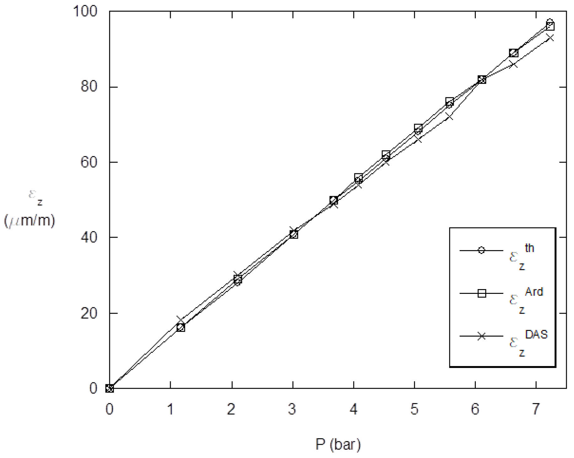
| 0 | 0 | 0 | 0 |
| 1.17 | 16 | 16 | 18 |
| 2.097 | 28 | 29 | 30 |
| 3.02 | 41 | 41 | 42 |
| 3.677 | 50 | 50 | 49 |
| 4.072 | 55 | 56 | 54 |
| 4.532 | 61 | 62 | 60 |
| 5.056 | 68 | 69 | 66 |
| 5.575 | 75 | 76 | 72 |
| 6.105 | 82 | 82 | 82 |
| 6.63 | 89 | 89 | 86 |
| 7.226 | 97 | 96 | 93 |
© 2019 by the authors. Licensee MDPI, Basel, Switzerland. This article is an open access article distributed under the terms and conditions of the Creative Commons Attribution (CC BY) license (http://creativecommons.org/licenses/by/4.0/).
Share and Cite
Garcia-Martin, R.; González-Briones, A.; Corchado, J.M. SmartFire: Intelligent Platform for Monitoring Fire Extinguishers and Their Building Environment. Sensors 2019, 19, 2390. https://doi.org/10.3390/s19102390
Garcia-Martin R, González-Briones A, Corchado JM. SmartFire: Intelligent Platform for Monitoring Fire Extinguishers and Their Building Environment. Sensors. 2019; 19(10):2390. https://doi.org/10.3390/s19102390
Chicago/Turabian StyleGarcia-Martin, Roberto, Alfonso González-Briones, and Juan M. Corchado. 2019. "SmartFire: Intelligent Platform for Monitoring Fire Extinguishers and Their Building Environment" Sensors 19, no. 10: 2390. https://doi.org/10.3390/s19102390
APA StyleGarcia-Martin, R., González-Briones, A., & Corchado, J. M. (2019). SmartFire: Intelligent Platform for Monitoring Fire Extinguishers and Their Building Environment. Sensors, 19(10), 2390. https://doi.org/10.3390/s19102390