Non-Uniform Concentric Rings Design for Ultra-Wideband Arrays


Abstract
:1. Introduction
2. Problem Statement
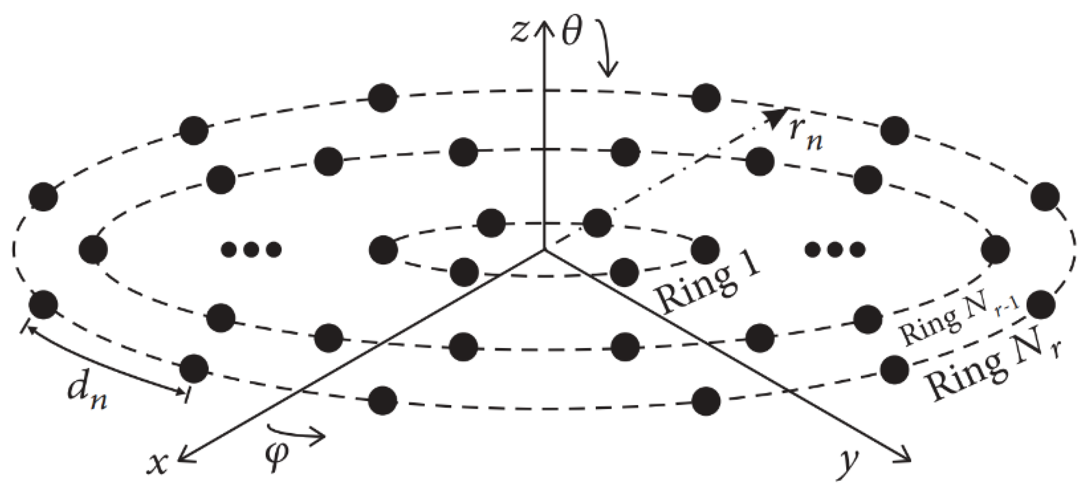
2.1. Array Factor Model
2.2. Optimization Procedure
3. Simulation Results
4. Conclusions
Author Contributions
Funding
Conflicts of Interest
References
- Huang, R.; Manoli, Y. Phased array and adaptive antenna transceivers in wireless sensor networks. In Proceedings of the Euromicro Symposium on Digital System Design, Rennes, France, 31 August–3 September 2004; pp. 587–592. [Google Scholar]
- Gregory, D.M.; Werner, D.H. Exploiting rotational symmetry for the design of ultra-wideband planar phased array layouts. IEEE Trans. Antennas Propag. 2013, 61, 176–184. [Google Scholar] [CrossRef]
- Petko, J.S.; Werner, D.H. The evolution of optimal linear polyfractal arrays using genetic algorithms. IEEE Trans. Antennas Propag. 2005, 53, 3604–3615. [Google Scholar] [CrossRef]
- Gorman, J.P.; Werner, D.H. Design of ultra-wideband, aperiodic antenna arrays with the CMA evolutionary strategy. IEEE Trans. Antennas Propag. 2014, 62, 1663–1672. [Google Scholar] [CrossRef]
- Agrawal, V.; Lo, Y. Mutual coupling in phased arrays of randomly spaced antenas. IEEE Trans. Antennas Propag. 1972, 20, 288–295. [Google Scholar] [CrossRef]
- Petko, J.S.; Werner, D.H. The pareto optimization of ultrawideband polyfractal arrays. IEEE Trans. Antennas Propag. 2008, 56, 97–107. [Google Scholar] [CrossRef]
- Gregory, M.D.; Werner, D.H. Ultrawideband aperiodic antenna arrays based on optimized raised power series representations. IEEE Trans. Antennas Propag. 2010, 58, 756–764. [Google Scholar] [CrossRef]
- Spence, T.G.; Werner, D.H. Design of broadband planar arrays based on the optimization of aperiodic tilings. IEEE Trans. Antenna. Propag. 2008, 56, 76–86. [Google Scholar] [CrossRef]
- Panduro, A.M.; Méndez, A.; Dominiguey-Cruz, R.; Romero, G. Design of non-uniform circular antenna arrays for side lobe reduction using the method of genetic algorithms. Int. J. Electron. Commun. AEUE 2006, 60, 713–717. [Google Scholar] [CrossRef]
- Stearns, C.O.; Stewart, A.C. An investigation of concentric ring antennas with low sidelobes. IEEE Trans. Antennas Propag. 1965, 18, 856–863. [Google Scholar] [CrossRef]
- Haupt, R.L. Optimized element spacing for low sidelobe concentric ring arrays. IEEE Transact. Antennas Propag. 2008, 56, 266–268. [Google Scholar] [CrossRef]
- Bianchi, D.; Genovesi, S.; A Monorchio, A. Constrained pareto optimization of wide band and steerable concentric ring arrays. IEEE Transact. Antennas Propag. 2012, 60, 3195–3204. [Google Scholar] [CrossRef]
- Bevelacqua, P.J.; Balanis, C. Geometry and weight optimization for minimizing sidelobes in wideband planar arrays. IEEE Transact. Antennas Propag. 2009, 57, 1285–1289. [Google Scholar] [CrossRef]
- Price, K.V.; Storn, R.M.; Lampinen, J.A. Differential Evolution: A Practical Approach to Global; Springer: Berlin, Germany, 2004. [Google Scholar]
- Balanis, C.A. Antenna Theory: Analysis and Design; John Wiley & Sons: Hoboken, NJ, USA, 2016. [Google Scholar]
- Zhang, L.; Yong-Chao, J.; Chen, B. Optimization of concentric ring array geometry for 3D beam scanning. Int. J. Antennas Propag. 2012, 2012, 625437. [Google Scholar] [CrossRef]
- Bencivenni, C.; Ivashina, M.; Maaskant, R. Reconfigurable aperiodic array synthesis by compressive sensing. In Proceedings of the 10th European Conference on Antennas and Propagation (EUCAP), Davos, Switzerland, 10–15 April 2016; pp. 1–3. [Google Scholar]
- Salas-Sanchez, A.A.; Fondevila-Gomez, J.; Rodriguez-Gonzalez, J.A.; Ares-Pena, F.J. Parametric synthesis of well-scanning isophoric pencil beams. IEEE Trans. Antennas Propag. 2017, 65, 1422–1427. [Google Scholar] [CrossRef]
- Subhashini, K.R.; Baranwal, A.; Kumar, A.P.; Reddy, M.S. Co sequent shaped Pattern Synthesis in Spherical Antenna Array with Excitation Optimization using Clever Algorithms. In Proceedings of the 2014 Annual IEEE India Conference (INDICON), Pune, India, 11–13 December 2014. [Google Scholar]
- Kumar, A.T.; Praven, K.R.; Subhasini, K.R. Non Uniform Element Angular Spacing of a Hemi Spherical Antenna Array for Vector Optimization Employing Natural Computing Techniques. In Proceedings of the 2013 Annual IEEE India Conference (INDICON), Pune, India, 13–15 December 2013. [Google Scholar]
- Rocha-Alicano, C.; Covarrubias-Rosales, D.; Brizuela-Rodriguez, C.; Panduro-Mendoza, M. Differential Evolution Algorithm Applied to Sidelobe Level Reduction on a Planar Array. AEU Int. J. Electromagn. Commun. 2007, 61, 286–290. [Google Scholar] [CrossRef]
- Elizarraras, O.; Mendez, A.; Reyna, A.; Panduro, M.A. Design of Spherical Antenna Arrays for a 3D Scannable Pattern using Differential Evolution. In Proceedings of the 2016 Loughborough Antennas and Propagation Conference (LAPC), Leicestershire, UK, 14–15 November 2016. [Google Scholar]
- Elizarraras, O.; Panduro, M.A.; Mendez, A.; Reyna, A.; Covarubias, D.H. Design of Circular Antennas Arrays of Circular Subarrays Exploting Rotational Symmetry. J. Electromagn. Waves Appl. 2017, 31, 1277–1288. [Google Scholar] [CrossRef]
- Medina, Z.; Reyna, A.; Panduro, M.A.; Elizarraras, O. Dual-Band Performance Evaluation of Time-Modulated Circular Geometry Array With Microstrip-Fed Slot Antennas. IEEE Access 2019, 7, 28625–28634. [Google Scholar] [CrossRef]


| Array Configuration | Number of Elements | PSLL (dB) dmin = 0.5λ | PSLL (dB) dmin = 10λ |
|---|---|---|---|
| Planar array (rotational symmetry) [2] | 220 | −16.91 | −12.05 |
| Planar array (rotational symmetry) [2] | 600 | −19.2 | −16.50 |
| Aperiodic tiling–Penrose optimized [8] | 551 | −16.49 | −6.50 |
| Aperiodic tiling–Danzer optimized [8] | 811 | −16.01 | −10.73 |
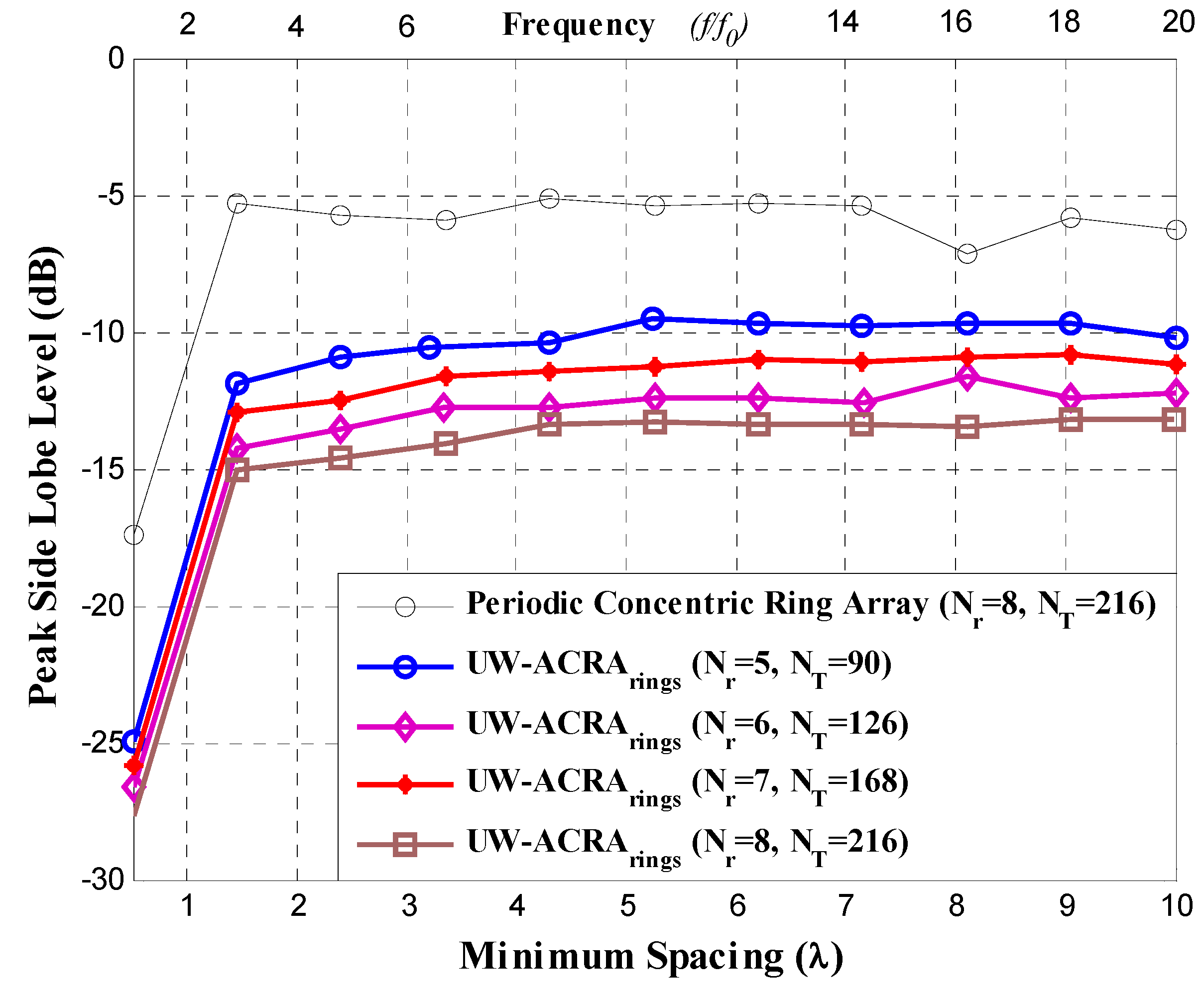
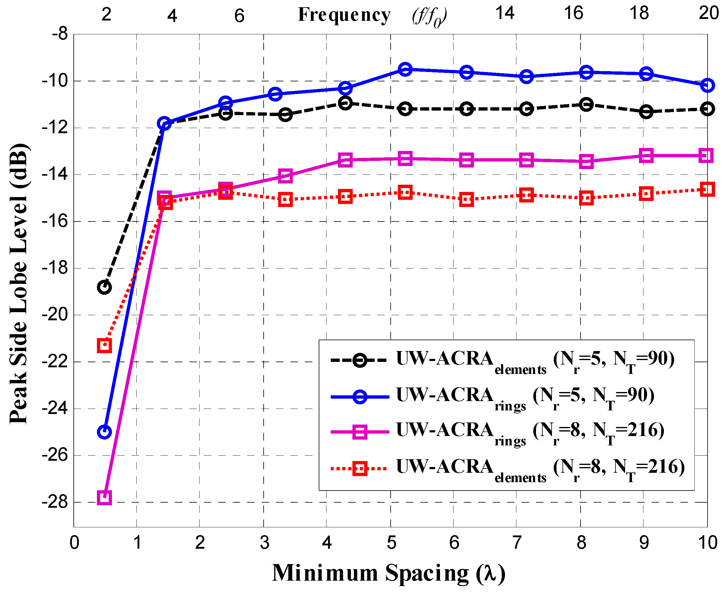
| UW-ACRArings | 90 | −24.95 | −10.21 |
| UW-ACRArings | 126 | −25.87 | −11.16 |
| UW-ACRArings | 168 | −26.59 | −12.24 |
| UW-ACRArings | 216 | −27.82 | −13.22 |
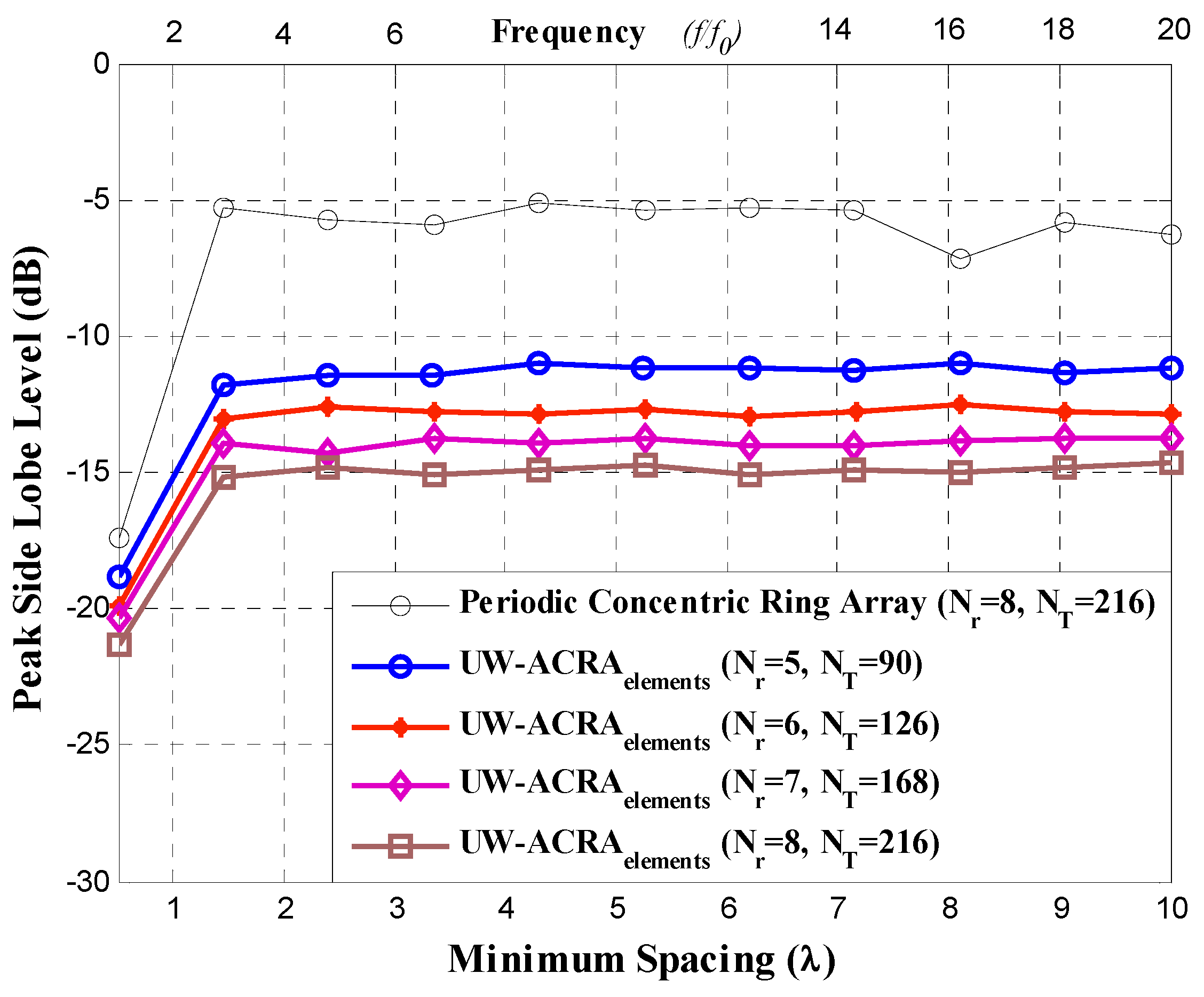
| UW-ACRAelements | 90 | −18.84 | −11.20 |
| UW-ACRAelements | 126 | −19.91 | −12.83 |
| UW-ACRAelements | 168 | −20.35 | −13.76 |
| UW-ACRAelements | 216 | −21.30 | −14.66 |
| Periodic Concentric Ring | 216 | −17.37 | −6.30 |
© 2019 by the authors. Licensee MDPI, Basel, Switzerland. This article is an open access article distributed under the terms and conditions of the Creative Commons Attribution (CC BY) license (http://creativecommons.org/licenses/by/4.0/).
Share and Cite
Panduro, M.A.; Reyna, A.; Covarrubias, D.H. Non-Uniform Concentric Rings Design for Ultra-Wideband Arrays. Sensors 2019, 19, 2262. https://doi.org/10.3390/s19102262
Panduro MA, Reyna A, Covarrubias DH. Non-Uniform Concentric Rings Design for Ultra-Wideband Arrays. Sensors. 2019; 19(10):2262. https://doi.org/10.3390/s19102262
Chicago/Turabian StylePanduro, Marco A., Alberto Reyna, and David H. Covarrubias. 2019. "Non-Uniform Concentric Rings Design for Ultra-Wideband Arrays" Sensors 19, no. 10: 2262. https://doi.org/10.3390/s19102262
APA StylePanduro, M. A., Reyna, A., & Covarrubias, D. H. (2019). Non-Uniform Concentric Rings Design for Ultra-Wideband Arrays. Sensors, 19(10), 2262. https://doi.org/10.3390/s19102262