Target Tracking While Jamming by Airborne Radar for Low Probability of Detection


Abstract
:1. Introduction
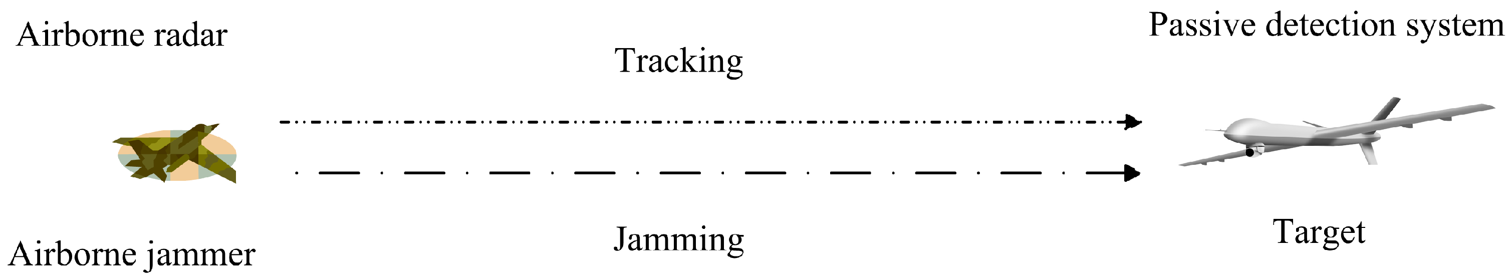
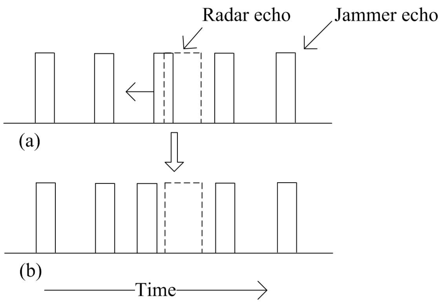
2. Problem Scenario
3. Adaptive Radiation Power of Airborne Jammer
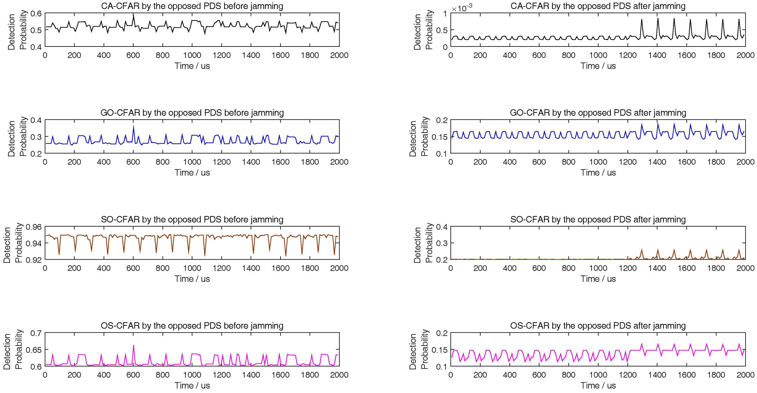
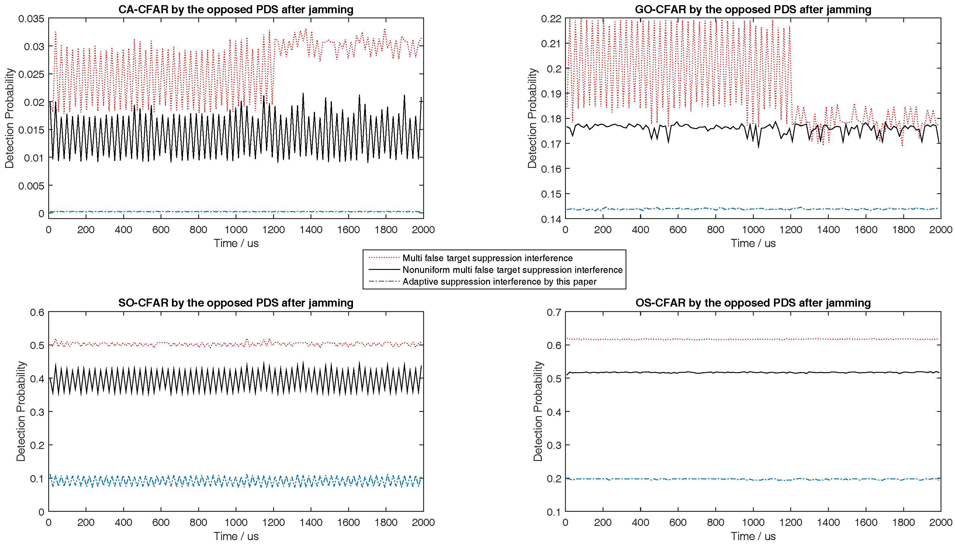
3.1. Detection Probability of CA-CFAR in Jamming
3.2. Detection Probability of GO-, SO-, OS-CFAR in Jamming
4. Track while Jamming Design
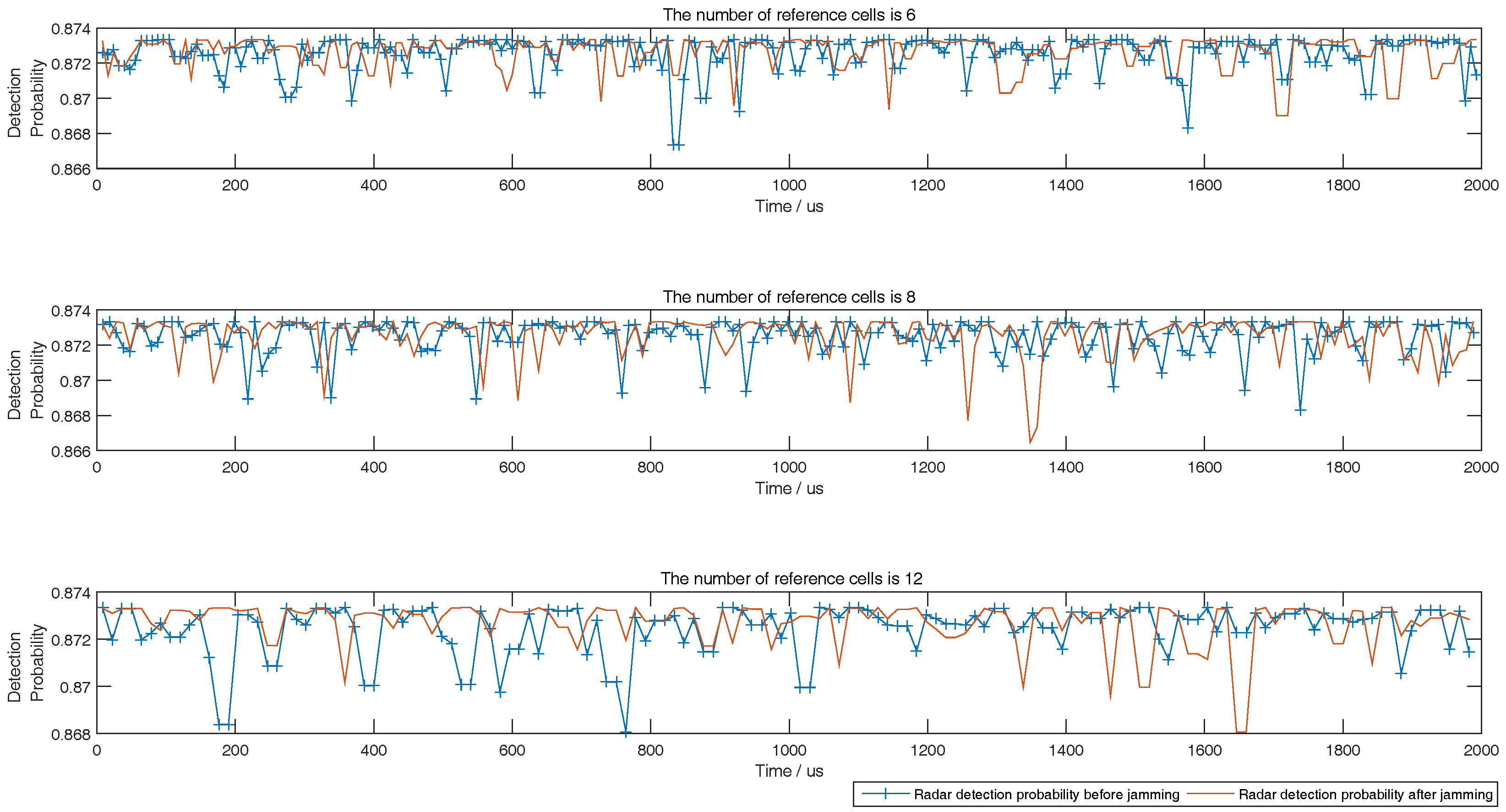
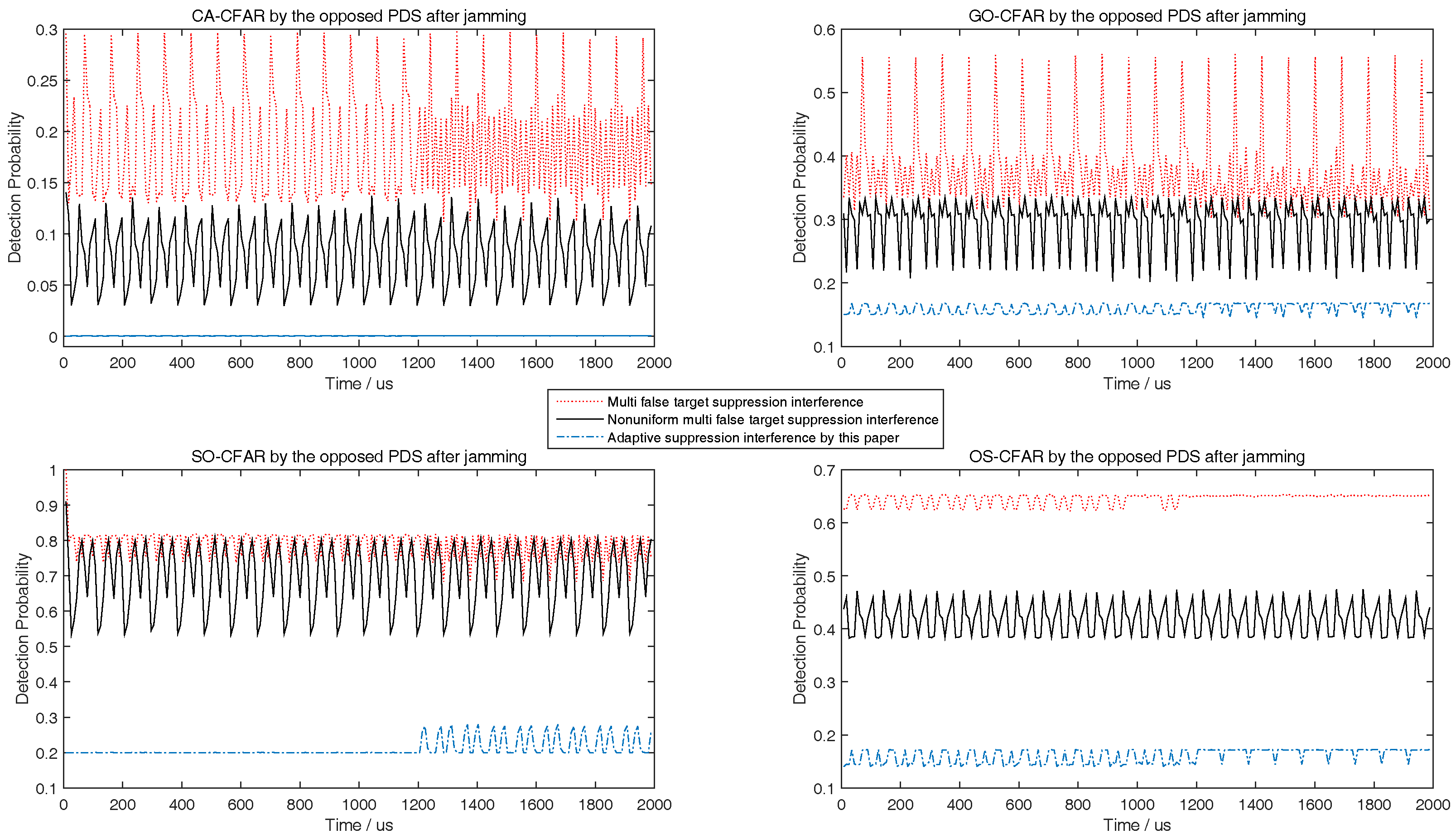
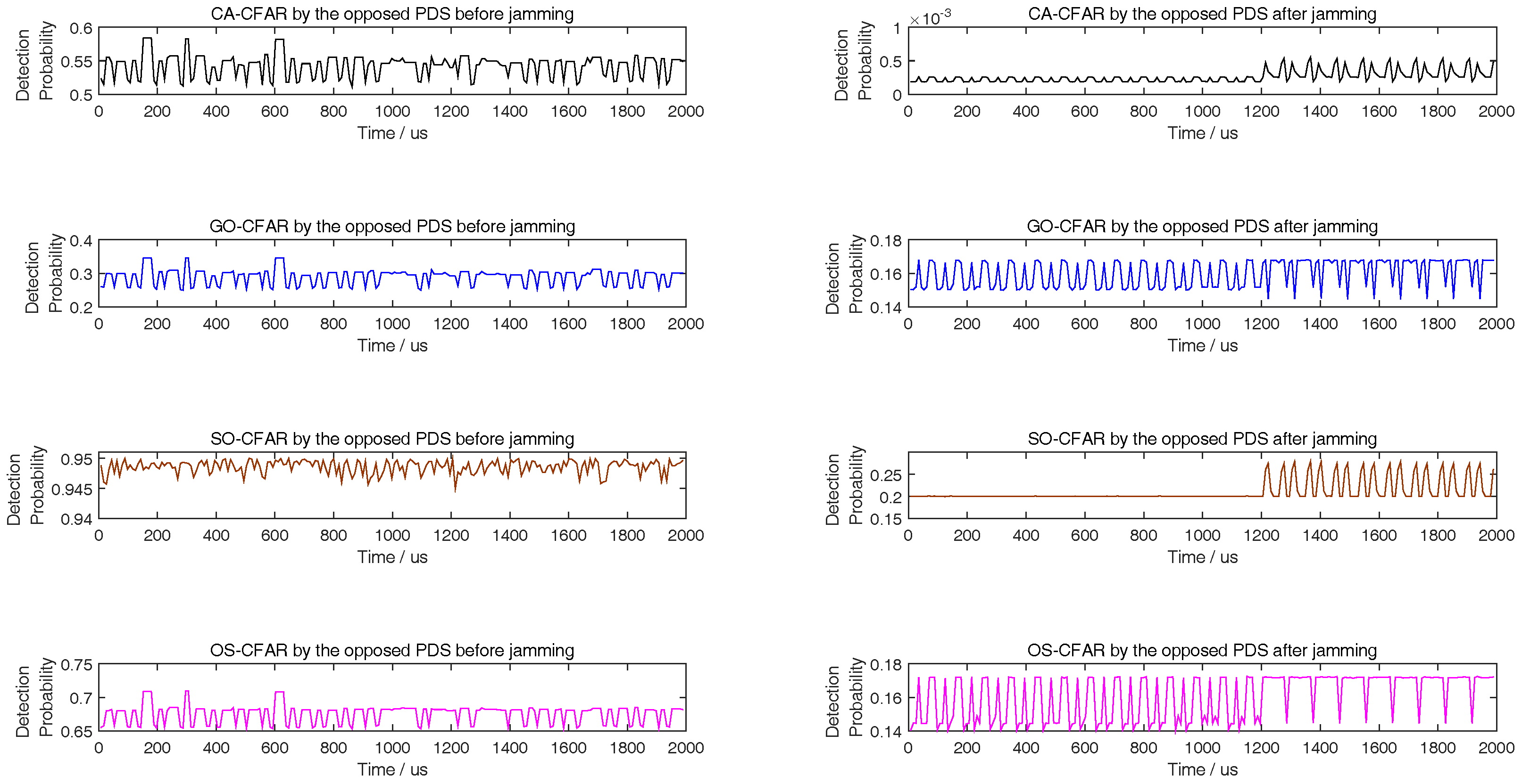
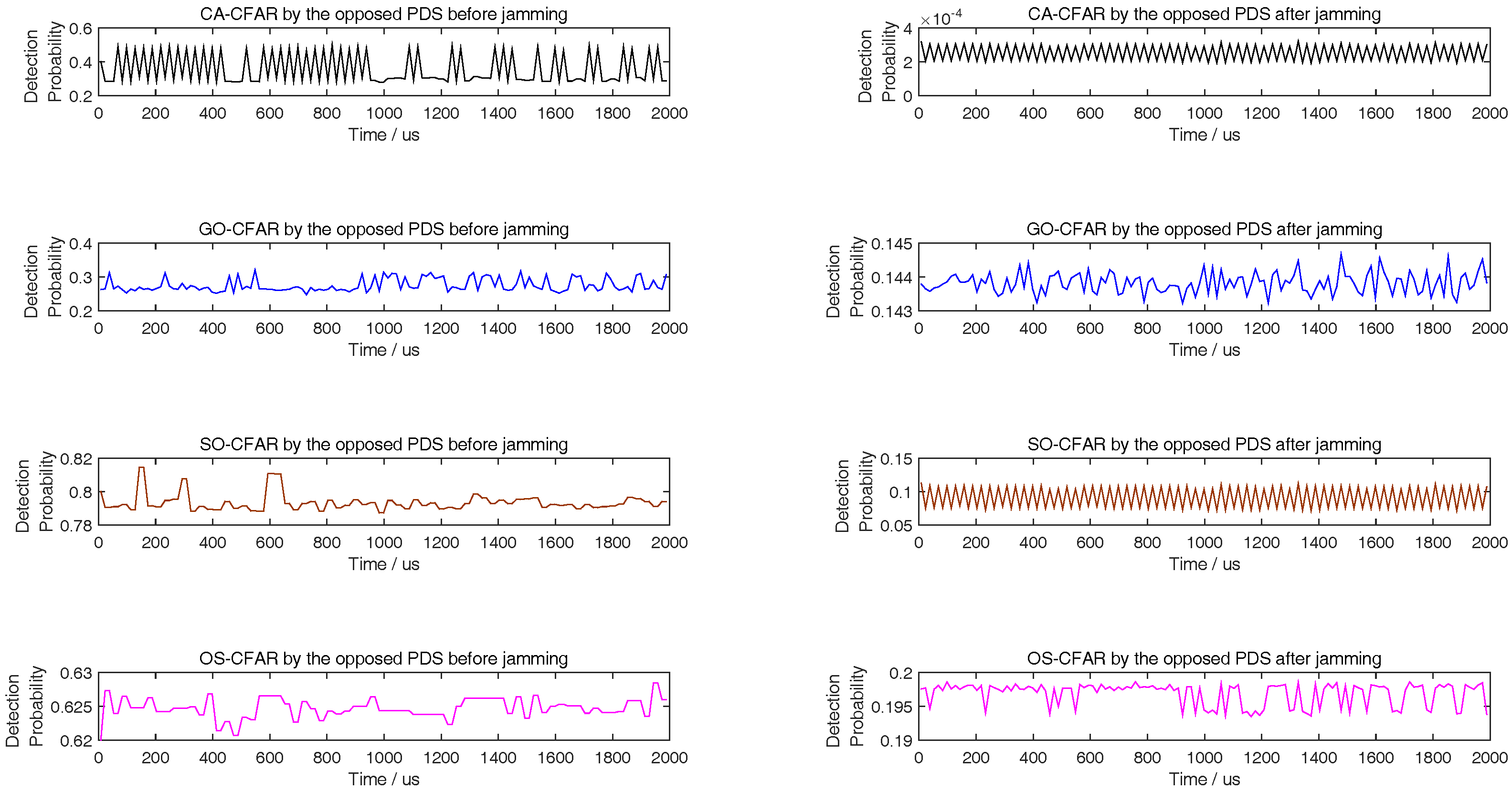
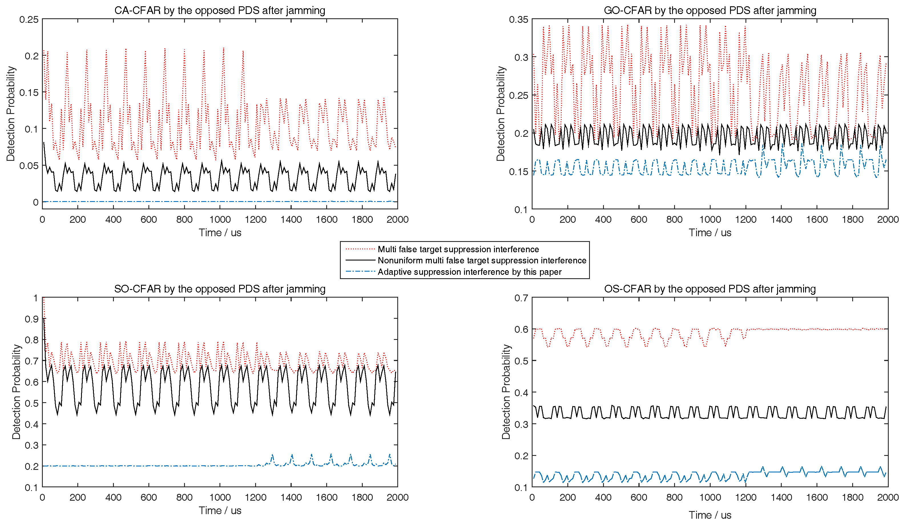
5. Simulations
6. Conclusions
Author Contributions
Funding
Acknowledgments
Conflicts of Interest
References
- Stove, A.G.; Hume, A.L.; Baker, C.J. Low probability of intercept radar strategies. IEE Proc. Radar Sonar Navig. 2004, 151, 249–260. [Google Scholar] [CrossRef]
- Fancey, C.; Alabaster, C.M. The metrication of low probability of intercept waveforms. In Proceedings of the International Waveform Diversity Design Conference, Niagara Falls, ON, Cananda, 8–13 August 2010; pp. 58–62. [Google Scholar]
- Shu, Y.R.; Chen, Z.P. Evaluation and simulation of LPI radar signals’ low probability of exploitation. In Proceedings of the 2nd International Conference on Image, Vision and Computing (ICIVC), Chengdu, China, 2–4 June 2017; pp. 842–846. [Google Scholar]
- Krishnamurthy, V. Emission management for low probability intercept sensors in network centric warfare. IEEE Trans. Aerosp. Electron. Syst. 2005, 41, 133–151. [Google Scholar] [CrossRef]
- Liao, J.; Yu, L.; Yu, L.X.; Luo, H. Method of radiation control for phased array radar based on LPI. Syst. Eng. Electron. 2011, 12, 2638–2642. [Google Scholar]
- Zhang, Z.K.; Zhou, J.J.; Wang, F. Research on optimal search performance of airborne phased array radar for radio frequency stealth. J. Astronaut. 2011, 9, 2023–2028. [Google Scholar]
- Liu, H.Q.; Wei, X.Z.; Li, F.; Xu, A. The real time control method of radar single radiation power based on RF stealth at the tracking. Acta Electron. Sin. 2015, 10, 2047–2052. [Google Scholar]
- Andargoli, S.M.H.; Malekzadeh, J. Target assignment and power allocation for LPI radar networks. In Proceedings of the International Symposium on Artificial Intelligence and Signal Processing (AISP), Tehran, Iran, 25–26 December 2015; pp. 234–239. [Google Scholar]
- She, J.; Wang, F.; Zhou, J.J. A novel sensor selection and power allocation algorithm for multiple-target tracking in an LPI radar network. Sensors 2016, 16, 2193. [Google Scholar] [CrossRef] [PubMed]
- She, J.; Zhou, J.J.; Wang, F.; Li, H.L. LPI optimization framework for radar network based on minimum mean-square error estimation. Entropy 2017, 19, 397. [Google Scholar] [CrossRef]
- Zhang, Z.K.; Tian, Y.B. A novel resource scheduling method of netted radars based on Markov decision process during target tracking in clutter. EURASIP J. Adv. Signal Process. 2016, 2016, 16. [Google Scholar] [CrossRef]
- Zhang, Z.K.; Salous, S.; Li, H.L.; Tian, Y.B. Optimal coordination method of opportunistic array radars for multi-target-tracking-based radio frequency stealth in clutter. Radio Sci. 2016, 50, 1187–1196. [Google Scholar] [CrossRef]
- Shi, C.G.; Zhou, J.J.; Wang, F. LPI based resource management for target tracking in distributed radar network. In Proceedings of the IEEE Radar Conference, Philadelphia, PA, USA, 1–6 May 2016; pp. 822–826. [Google Scholar]
- Shi, C.G.; Salous, S.; Wang, F.; Zhou, J.J. Power allocation for target detection in radar networks based on low probability of intercept: A cooperative game theoretical strategy. Radio Sci. 2017, 52, 1030–1045. [Google Scholar] [CrossRef]
- Shi, C.G.; Salous, S.; Wang, F.; Zhou, J.J. Low probability of intercept based adaptive radar waveform optimization in signal dependent clutter for joint radar and cellular communication systems. EURASIP J. Adv. Signal Process. 2016, 2016, 111. [Google Scholar] [CrossRef] [PubMed]
- Shi, C.G.; Wang, F.; Sellathurai, M.; Zhou, J.J.; Salous, S. Power minimization based robust OFDM radar waveform design for radar and communication systems in coexistence. IEEE Trans. Signal Process. 2017. [Google Scholar] [CrossRef]
- Shi, C.G.; Wang, F.; Sellathurai, M.; Zhou, J.J. Low probability of intercept based multicarrier radar jamming power allocation for joint radar and wireless communications systems. IET Radar Sonar Navig. 2017, 11, 802–811. [Google Scholar] [CrossRef]
- Shi, C.; Wang, F.; Salous, S.; Zhou, J. Optimal Power Allocation Strategy in a Joint Bistatic Radar and Communication System Based on Low Probability of Intercept. Sensors 2017, 12, 2731. [Google Scholar] [CrossRef] [PubMed]
- Liu, Q.; Wang, X.H.; Wang, X.; Cheng, S.Y. A study on methods of active Barrage Jamming Power assignment based on Multi-targets. Fire Control Command Control 2012, 5, 164–166. [Google Scholar]
- Song, H.F.; Wu, H.; Cheng, S.Y.; Luo, C.S. Adaptive control method of AECM power based on radio frequency stealth. Fire Control Command Control 2014, 6, 118–121. [Google Scholar]
- Wang, R.J.; Wang, X.; Cheng, S.Y. Power control of defensive electronic countermeasures based on radio frequency stealth. Telecommun. Eng. 2015, 1, 19–26. [Google Scholar]
- Hao, H.; Zeng, D.; Ge, P. Research on the Method of Smart Noise Jamming on Pulse Radar. In Proceedings of the Fifth International Conference on Instrumentation Measurement, Computer, Communication and Control, Qinhuangdao, China, 18–20 September 2015; pp. 1339–1342. [Google Scholar]
- He, Y. Radar Target Detection and CFAR Processing; TsingHua University Press: Beijing, China, 2011. [Google Scholar]
- Melebari, A.; Melebari, A.; Alomar, W. The effect of windowing on the performance of the CA-CFAR and OS-CFAR algorithms. In Proceedings of the IEEE Radar Conference, Hangzhou, China, 27–30 October 2015. [Google Scholar]
- Cai, L.; Ma, X.; Yan, S. Some Analysis of Fuzzy CAGO/SO CFAR Detector in Non-Gaussian Background. In Proceedings of the IEEE International Intelligent Systems and Applications, Cairo, Egypt, 29 November–1 December 2010; pp. 1–4. [Google Scholar]
- Luo, Y.; Chen, H.; Pang, L. The design of frequency domain CFAR detector based on large-points DFT. In Proceedings of the IET International Radar Conference, Guilin, China, 20–22 April 2009; pp. 1–4. [Google Scholar]
- Liu, X.; Suo, J.; Liu, R. The radar clutter processor with wavelet floating threshold. In Proceedings of the CIE International Conference on Radar Proceedings, Xi’an, China, 15–18 October 2001; pp. 1001–1005. [Google Scholar]
- An, P.; Kodituwakku, S.; Cao, T.T.V. A CFAR algorithm based on summations processing. In Proceedings of the IEEE International Conference on Acoustics, Speech and Signal Processing, Queensland, Australia, 19–24 April 2015; pp. 3951–3955. [Google Scholar]
- Schleher, D.C. LPI radar: Fact or fiction. IEEE Aerosp. Electron. Syst. Mag. 2006, 21, 3–6. [Google Scholar] [CrossRef]
- Zhang, Z.K.; Zhou, J.J. Multiple-target tracking with adaptive sampling intervals for phased-array radar. J. Syst. Eng. Electron. 2011, 22, 760–766. [Google Scholar] [CrossRef]
- Zheng, G.Y.; Wang, H.B.; Xie, X.B. Study on the denial distance of MFT jamming against CFAR detection radars. J. Spacecraft TT C Technol. 2013, 32, 177–181. [Google Scholar]
- Zhang, Y.R.; Li, Y.J.; Li, M.L. Suppress jamming technique of multiple false targets on interrupted-sampling and non-uniform periodic repeater. Acta Electron. Sin. 2016, 44, 46–53. [Google Scholar]


| Radar | Values | Radar | Values | Radar | Values |
|---|---|---|---|---|---|
| 30 dB | 30 dB | 1 m | |||
| L | 3 dB | 1 MHz | 2 dB | ||
| 15 dB | 1 s | 10 ms | |||
| 20 kw | 10 w | 0.03 m |
| Time(s) | State Equations |
|---|---|
© 2018 by the authors. Licensee MDPI, Basel, Switzerland. This article is an open access article distributed under the terms and conditions of the Creative Commons Attribution (CC BY) license (http://creativecommons.org/licenses/by/4.0/).
Share and Cite
Wang, F.; Cong, X.-B.; Shi, C.-G.; Sellathurai, M. Target Tracking While Jamming by Airborne Radar for Low Probability of Detection. Sensors 2018, 18, 2903. https://doi.org/10.3390/s18092903
Wang F, Cong X-B, Shi C-G, Sellathurai M. Target Tracking While Jamming by Airborne Radar for Low Probability of Detection. Sensors. 2018; 18(9):2903. https://doi.org/10.3390/s18092903
Chicago/Turabian StyleWang, Fei, Xin-Bo Cong, Chen-Guang Shi, and Mathini Sellathurai. 2018. "Target Tracking While Jamming by Airborne Radar for Low Probability of Detection" Sensors 18, no. 9: 2903. https://doi.org/10.3390/s18092903
APA StyleWang, F., Cong, X.-B., Shi, C.-G., & Sellathurai, M. (2018). Target Tracking While Jamming by Airborne Radar for Low Probability of Detection. Sensors, 18(9), 2903. https://doi.org/10.3390/s18092903