1. Introduction
The BeiDou demonstration system (BDS-1), the regional service system (BDS-2), and the global service system (BDS-3) have been developed by a “three-step” strategy [
1]. BDS-1 consists of geosynchronous orbit (GEO) satellites launched from 2000 to 2003. On 27 December 2012, the BeiDou system, which has a space constellation of five GEO, five inclined geosynchronous orbit (IGSO) satellites, and four medium Earth orbit (MEO) satellites, began to provide services to the Asia Pacific region. BeiDou started to evolve from a regional service capability to a global service capability with the launch of the new-generation BeiDou experimental satellite (BeiDou, I1-S) into orbit in March 2015. Five BDS-3 experimental satellites (C31–C35) and two BDS-3 satellites (C19 and C20) were in orbit by the end of November 2017 [
2]. Moreover, the new-generation BeiDou system plans to achieve a 30 satellites network by 2020 (three GEO, 24 MEO, and three IGSO) providing global navigation, positioning, and timing services [
3].
However, the orbit accuracy of BeiDou is currently one of the major challenges with the expanding application of BeiDou in the field of navigation and positioning. Researchers have assessed the BDS-2 orbit [
4,
5,
6] well to improve the accuracy and relevant algorithms of BeiDou orbit determination. The results showed that the three-dimensional root-mean-square error (3D RMS) of BDS-2 one-day overlapping arc for MEO (and IGSO) and GEO were improved from 0.5 m and 3.0 m to 0.2 m and 1.0 m, respectively. Furthermore, the orbit models of BDS-2 were refined in recent studies, which included the introduction of a radial constant acceleration of GEO [
7,
8], yaw attitude model [
9,
10], hardware delay [
11], and inter-frequency bias (IFB) [
12] to further improve the orbit accuracy. Recent assessment studies suggested that the satellite laser range (SLR) residuals from different data analysis centers for BDS-2 orbits are better than 0.2 m for MEO (and IGSO) and 0.5 m for GEO [
11], respectively. In general, BDS-2 orbits have been improved and refined over the years. For the new-generation BeiDou experimental satellites (hereafter called BDS-3) orbits, in [
13,
14], four BDS-3 orbits (C31–C34) were estimated based on the international GNSS Monitoring and Assessment System (iGMAS) and the Multi-GNSS Experiment (MGEX) stations. Due to restrictions in the tracking networks, the results suggested that the radial and along-directions of one-day overlapping arc errors were between 0.10 m and 0.25 m. In addition, the RMS of the SLR residuals was at the 0.1–0.3 m level. However, the impacts of orbit models, such as solar radiation pressure and yaw model, were not analyzed in their studies. In [
15], three-month BDS-3 orbits were acquired based on the same methods as BDS-2 orbit determination, which was analyzed in terms of yaw attitude and solar radiation pressure models. Moreover, to further improve BDS-3 orbit accuracy, inter-satellite link (ISL) and autonomous orbit determination were taken into account [
16,
17,
18]. However, compared with the BDS-2 orbit, only preliminary studies on BDS-3 orbit determination, which should be focused on, were conducted.
To improve the accuracy of BDS-3 orbits, it should be noted that the data availability and the quality of tracking networks used are the two main factors that restrain the orbit accuracy in the BDS-3 orbit determination, which directly affect the accuracy of orbit determination [
19]. Therefore, in [
20,
21,
22], the BDS-3 signals and its quality were evaluated, and the results, compared to BDS-2, showed that the data quality of the BDS-3 improves significantly. In addition, the satellite-induced multipath effects along with the elevation in BDS-2 disappeared in the BDS-3 observations. However, because the new signals of BDS-3 satellites remain in the internal test stage, the BDS-3 signals are mainly tracked by the iGMAS network [
13], the data quality of which was not involved in the related analysis. Meanwhile, from the experiments of data quality analysis (
Section 2), it was found that the smaller cycle-slip ratio, especially for GPS, in the iGMAS tracking data was apparent. Thus, research on the optimal iGMAS observations is vital for the BDS-3 orbit determination.
To control the GNSS observation quality, the effective cycle-slip detection and repair algorithm plays a key role [
23]. When triple-frequency observations of BDS and GPS are received, the linear combinations of triple-frequencies make it easy to realize cycle-slip detection and repair in each frequency [
24]. However, most of stations for tracking BDS-3 signals are still double frequencies. In [
25], the Turboedit algorithm was proposed, which has been widely used in the field of navigation and positioning. However, it should be noted that the observation noise and poor data quality might impose restrictions on this algorithm, especially for omitting the observations with several cycle slips that reduces the data availability of the network directly. Therefore, an accurate cycle-slip detection and repair algorithm in BDS-3 orbit determination should be proposed to improve data availability given the limited data sources and the poor quality of iGMAS data.
Furthermore, to increase the data availability, the estimation of parameters based on the normal equation stacking (NES) of several networks is another method, thereby improving the parameter’s strength in BDS-3 orbit determination. Since the iGMAS network can receive BDS-3 signals (B1 and B3) with a few stations but not consistent with BDS-2 signals (mainly B1 and B2) tracked by the MGEX network. The relevant studies about the NES were discussed based on the single-day into multi-day solutions [
26,
27,
28]. These served as references for improving the parameter estimation in BDS-3 orbit determination in this study.
To determine four new-generation BeiDou (BDS-3) experimental satellites (C31, C32, C33, C34; C35 could not be tracked by iGMAS) orbits with the given limited data availability and poor data quality of iGMAS data, this study mainly proposes an improved cycle-slip detection and repair algorithm and two optimized methods based on iGMAS and MGEX networks. In
Section 2, the quality of iGMAS observations is briefly analyzed. Then, an improved cycle-slip detection and repair algorithm for iGMAS is proposed to solve the poor data quality and low data availability. In
Section 3, two orbit determination methods are discussed based on the combination of MGEX and iGMAS observations. In
Section 4, orbit accuracy analysis is conducted by overlapping arc errors and SLR residuals, respectively.
2. Improved Cycle-Slip Detection and Repair Algorithm
In the analysis data of sixteen iGMAS stations could be obtained by the end of December 2016, among them, nine stations tracked BDS-3 signals. To understand the data quality of iGMAS, two stations (LHA1 and WHU1) were selected to conduct data quality analysis. Meanwhile, it should be noted that the corresponding MGEX stations (LHAZ and JFNG) were the same location stations and can be used for data quality comparison. In the experiments, the GPS data from day of year (DOY) 156 to 160 in 2017 were selected as examples. The observation effective rate, MP1 and MP2, and the average cycle-slip ratio (CSR) (the ratio between the number of observations and epochs with cycle slips) [
29] are listed in
Table 1 based on the Multi-GNSS data analysis software (MTEQC), which is developed and improved by the authors. Moreover, the effective rate and CSR of BDS-3 in iGMAS data are also listed in
Table 1, while the BDS-2 of MGEX was taken as a reference to compare BeiDou data quality of both networks.
In
Table 1, the cut-off of elevation angle was set as 5 degrees. Analyses of observations taken at the same sites revealed that the data quality of GPS observations is considerably poorer in iGMAS than for MGEX, especially focusing on cycle slips and multipath. In addition, investigating BDS-2 and BDS-3 observations, the cycle slips are much more numerous in MGEX. However, the full exploitation of observations is necessary due to limited data availability in BDS-3 orbit determination. Thus, the high-accuracy cycle-slip detection and repair algorithm for iGMAS and MGEX is a prerequisite of the BDS-3 orbit determination.
To optimize the observations quality in BDS-3 orbit determination, based on the traditional Turboedit algorithm [
25], the following issues may occur when processing the cycle slips in iGMAS data: (1) the detection and repair of the small cycle-slips is inaccurate given the larger noise of iGMAS data (MP1 and MP2 are larger than for MGEX in
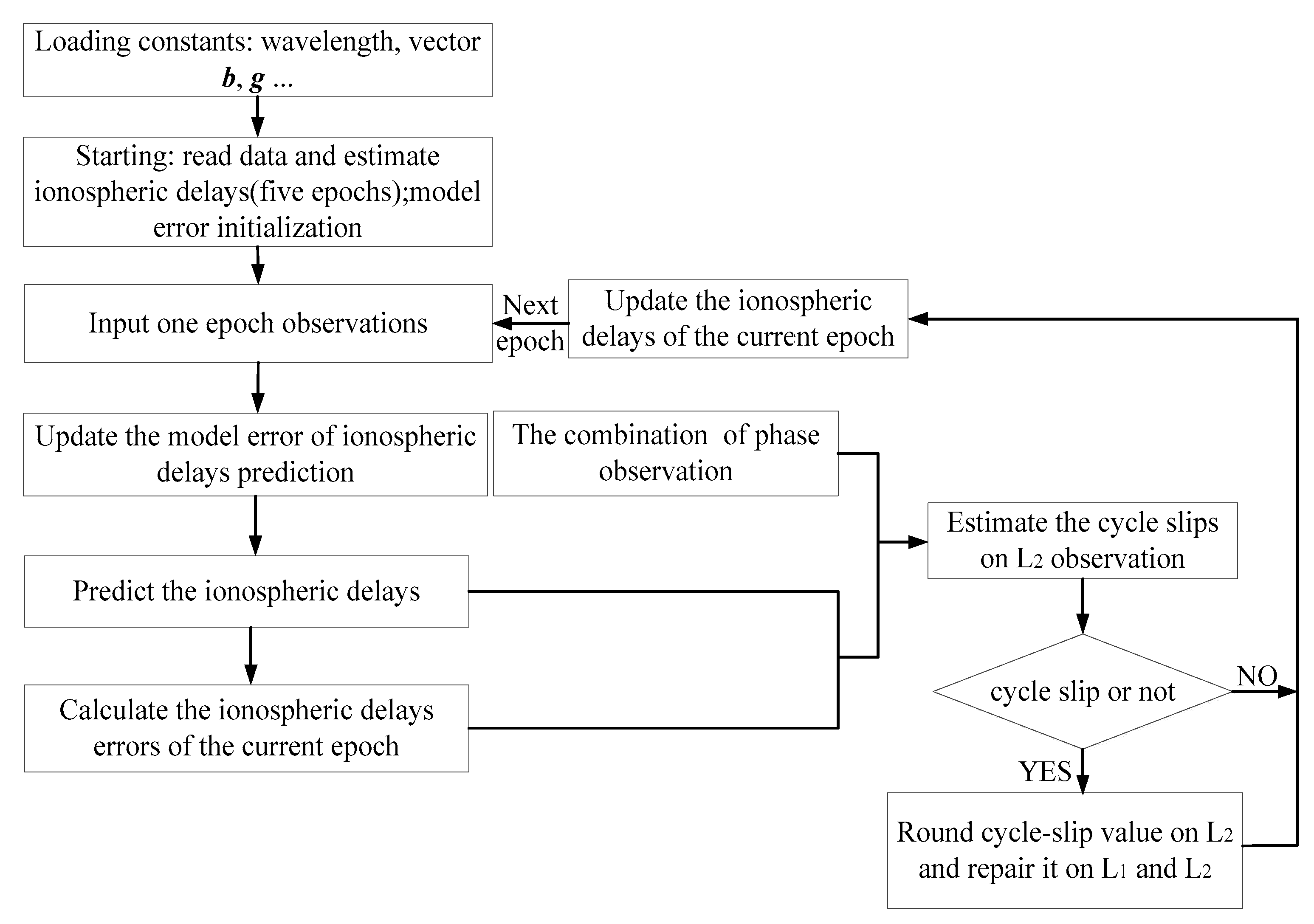
Table 1); (2) the data piece with several cycle slips is eliminated directly, thereby reducing the data availability of the tracking observations; and (3) the algorithm is insensitive to some special combinations (such as the same cycle slips in each frequency), especially small cycle slips. Therefore, an improved cycle-slip detection and repair algorithm for iGMAS data is presented in the study that is based on the accurate prediction of the ionospheric delays. The corresponding algorithm is presented below.
The GNSS observation equation is [
30]:
Equation (1) shows the pseudo-range and phase observation equation; i denotes the carrier frequency; is the geometric distance between the satellite and the station; c is the speed of light; are the satellite and receiver clock offsets, respectively; represents the troposphere delay; is the ionospheric delay on L1 frequency; is the ionospheric delay coefficient; are the corresponding observation noise; is the wavelength; and is the integer ambiguity.
The ambiguity of Melborne-Wübbena (MW) combination reads:
where
is the widelane wavelength, and
is the combined noise.
The cycle slips of
L1 and
L2 are assumed as
, respectively; thus, after determining the epoch difference of the MW combination, the combined ambiguity is:
where
is the noise. Then, Equation (3) is inserted into the phase equation as epoch difference:
In Equation (4), , , .
Assume
. According to Equation (4), the cycle slips on
L2 observation can be expressed as:
and:
It should be noted that the accurate estimation of the cycle-slip values on
L2 requires further analysis of
Q. The parameter
in Equation (4) can be expressed as the difference between the estimation error of the former epoch
and the prediction error of the current epoch
:
where
is the prediction model error. However, for the epoch without cycle slips, the phase observation equation can be obtained as below:
where
and
. The ionospheric delay can be expressed as follows:
The coefficients of the ionospheric delays are assumed as
b. Thus, the estimated ionospheric delays can be written as:
However, the variations of the total electron content (TEC) could be assumed as a polynomial model during a short time (one hour) given an inactive ionosphere period, which can be concluded from the estimated errors of ionospheric delays (Figure 4). Therefore, this study takes a polynomial function to fit the ionospheric delays in short time (five epochs). Thus:
where
is the polynomial coefficients;
t is the epoch point, and
is the model fitting residual. The ionospheric delay is assumed to be fitted by five epochs. Then:
where
,
,
and
The coefficients of polynomial function are computed as follows:
Then, the current epoch is set as
t = 0. Therefore, the prediction of ionospheric delay is:
where
represents the coefficients of five ionospheric delays. By inserting Equations (7) and (14) into Equation (6), we obtain:
In Equation (6),
Q can be simplified as:
where
and
is an identity matrix with two dimensions. Based on the matrix inversion lemma,
Q can be expressed as:
where
, and
.
The model error from Equations (15) to (18) is:
where
is the impact factor of the previous epoch, and
.
Therefore, in Equation (5), the solution of
can be expressed as:
According to the above equations, the cycle-slip values on L2 can be calculated accurately by inserting Equation (20) into Equation (5). Moreover, inserting the fractional parts on L2 adjusted to integer numbers into Equation (3), can solve the cycle slips on L1 observations. In the improved cycle-slip detection and repair algorithm, the estimated ionospheric delay in Equation (10) contains the constant biases, namely, integer ambiguity and hardware delay in adjacent epochs, which do not affect the cycle-slip detection at all.
In this study, an improved algorithm of double-frequencies’ cycle-slip detection and repair is proposed. The new algorithm considers the drawbacks of the inaccurate traditional Turboedit (see Table 4) to refine the data preprocessing based on a predicted ionospheric delay. A polynomial prediction model is used to acquire the ionospheric delays of the current epoch, which takes the correlation of adjacent epochs into consideration. Moreover, the cycle slips are detected and repaired epoch-wise to increase data availability. In general, compared with the traditional Turboedit, the advantages of the improved algorithm can be summarized as follows: (1) the algorithm, which is based on the predicted ionospheric delay information rather than a geometry-free (GF) combination, solves the problem of special cycle-slip combinations in two frequencies (such as 1:1 and 9:7 for L1:L2 in GPS observations); (2) the improved algorithm is more accurate than MW and GF combinations in Turboedit, which has to fit the GF and ignores the correlation of the ionospheric delays; (3) in the estimation of ionospheric delays, the pseudo-range observations, which have an impact on the detection and repair of the small cycle-slips as the larger noise than phase observations, are disregarded; and (4) the variations in the ionospheric delay estimation caused by constant biases in Equation (14) are zero when ().
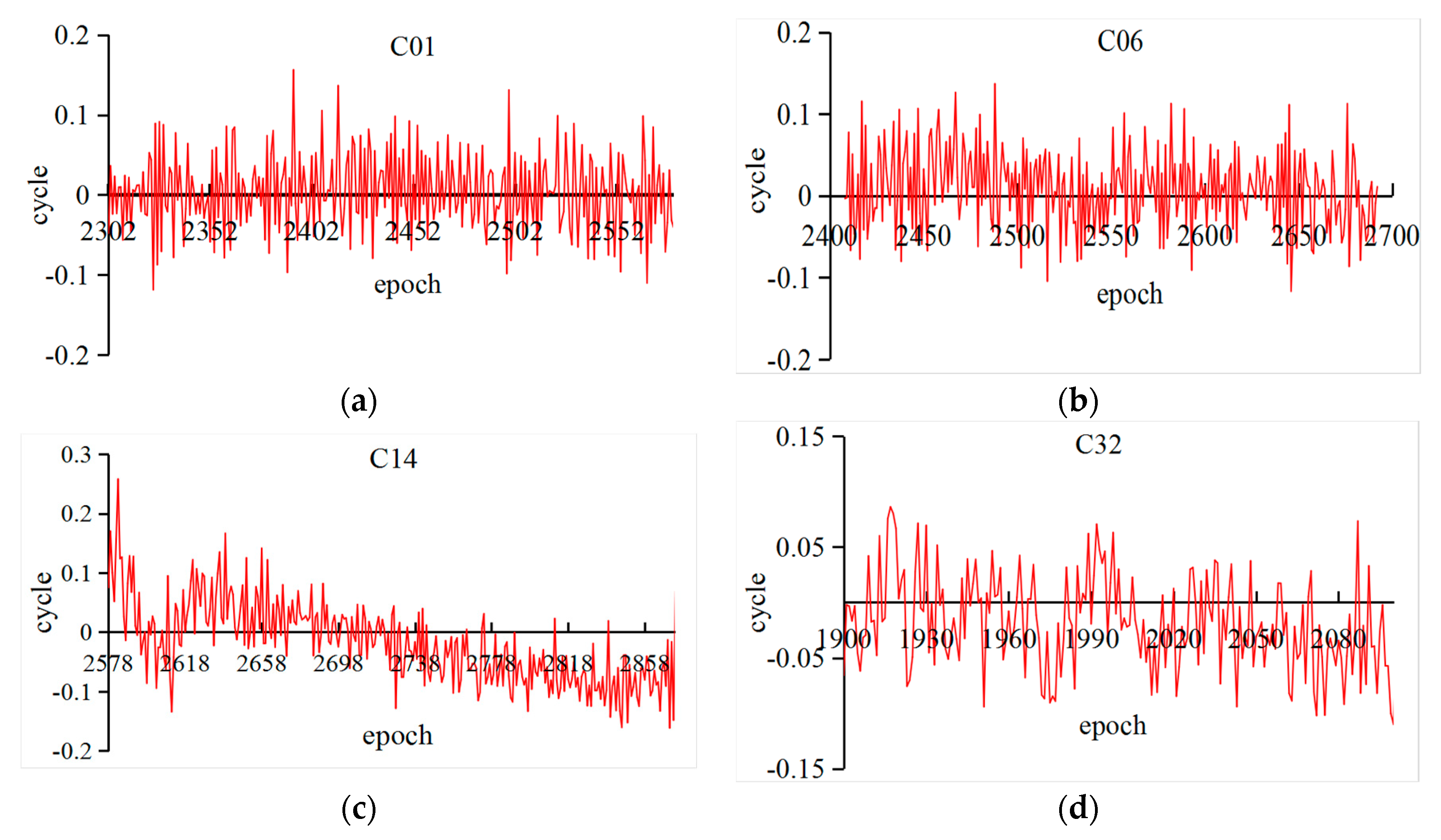
To illustrate the improved cycle-slip detection and repair algorithm,
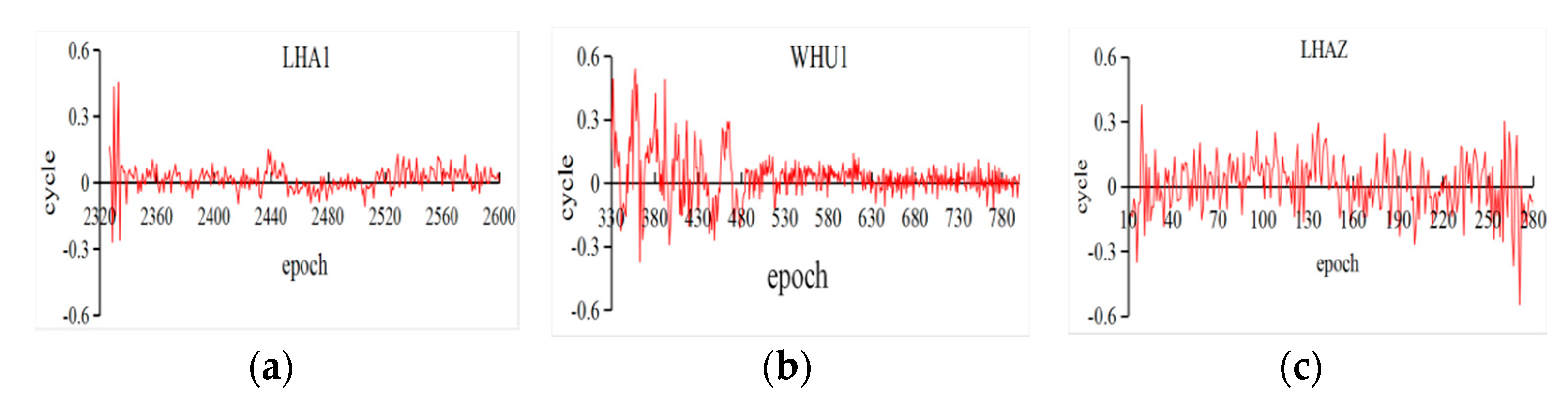
Figure 1 shows the flow chart of the above procedure. Moreover, the data from iGMAS and MGEX tracking networks are selected to verify the reliability and availability of the improved algorithm. The fractional part of the estimated
L2 based on the improved algorithm is extracted by no cycle-slip observations of iGMAS (WHU1 and LHA1) and MGEX (LHAZ). Four days (DOY 183–186, 2017) of observations with a 30 s sampling interval were chosen to conduct the cycle-slip detection and repair experiments and then to fully explain the accuracy of the improved algorithm. Due to the fact that the experimental datasets were extremely large, the G01 and C01, C06, C14, and C32 were selected as the representative of GPS, and GEO, IGSO, MEO, and BDS-3 in BeiDou to analyze the results, respectively.
Table 2 summarizes the maximum, average, and standard deviation (STD) of the fractional parts of the estimated cycle slips and the properness after rounding on G01. Similarly, results of BeiDou satellites (C06 missed on DOY 184) are listed in
Table 3, in which only LHA1 is listed to conduct the corresponding analysis.
In
Table 2, the average and STD of the fractional parts of the estimated
L2 are less than 0.2 cycles, whereas some of the maximum values are beyond 0.5 cycles, especially for WHU1. Moreover, based on the improved algorithm, a few wrong cycle slips were found in this study. However, the properness is beyond 99% for all experiments, in which the incorrect estimation for iGMAS is slightly higher than for MGEX observations. It can be explained that the larger noise of iGMAS observations than for MGEX causes the inaccurate estimation of ionospheric delay from the analysis of
Table 1.
In
Table 3, the properness of four days for different BeiDou satellites on LHA1 reached upwards of 100%. Meanwhile, the maximum values are smaller than for G01 in
Table 2, which can ensure the properness of rounding the fractional parts. However, it should be noted that the results of C32 seem to be better than for BDS-2. According to the experiments, it proved that the improved algorithm is reliable for BeiDou observations, especially for BDS-3 experimental satellites. Furthermore, the fractional parts of estimated cycle slips in all epochs are demonstrated in
Figure 2 and
Figure 3 to provide the details of the improved algorithm.
In
Figure 2, the fractional parts of the G01 (DOY 183) at three stations are drawn; it could be found that the fractional parts of iGMAS observations are convergent as the epoch increases. Since the improved algorithm is epoch-wise processing, the results are influenced by the noise of observations at the beginning. In addition, the MGEX observations are almost less than 0.3 cycles. Similarly,
Figure 3 shows the results of three types BeiDou satellites and BDS-3 experimental satellites, which are based on LHA1 observations on DOY 183. Simultaneously, the corresponding fractional parts are less than 0.2 cycles. However, the result was slightly worse for MEO than for IGSO and GEO satellites and its trend could be caused by the BeiDou satellite-induced biases [
31]. The accuracy of the improved algorithm proposed in this study can meet the requirements of orbit determination by testing iGMAS and MGEX observations (without cycle slips). The properness of rounding reached 100%, except for a few errors.
Then, a group of cycle slips was inserted into the observations to test the reliability of the improved algorithm. Due to the fact that the Turboedit could not solve the special combinations on different frequencies, such as 1:1 or 9:7 for cycle slips on
L1 and
L2 of GPS, the experiment selected six types of combinations ((0,1), (1,0), (1,1), (9,7), (100,1), and (790,563)) to analyze the improved algorithm [
32]. The observations from the last experiment were inserted cycle slips, and the repaired results are based on rounding the float estimates.
Table 4 only summarizes the results of G01, C01, C06, C14, and C32 based on LHA1 on DOY 183. In
Table 4, the cycle slips in GPS or BeiDou observations, correspondingly, were completely corrected based on the improved algorithm. However, the estimated cycle slips at epoch 2600 were (0.525,0.698), which is difficult to fix as the real values in the ambiguity resolution. In this study, from the results of all experiments, this phenomenon need not be taken into consideration as the very few numbers did not impact the corresponding conclusions. Moreover, to further analyze the improved algorithm, the results of Turboedit were also listed in
Table 4. The experimental results show that the ability of the improved algorithm to detect and repair cycle slips outperforms the Turboedit approach, especially for repairing values. Furthermore, the differences between the estimated and the predicted ionospheric delays are also calculated to test the accuracy of the predicted polynomial model.
Figure 4 displays the ionospheric delay residuals for G01, C06, C14, and C32 (LHA1) calculated from the same data as
Figure 2. In
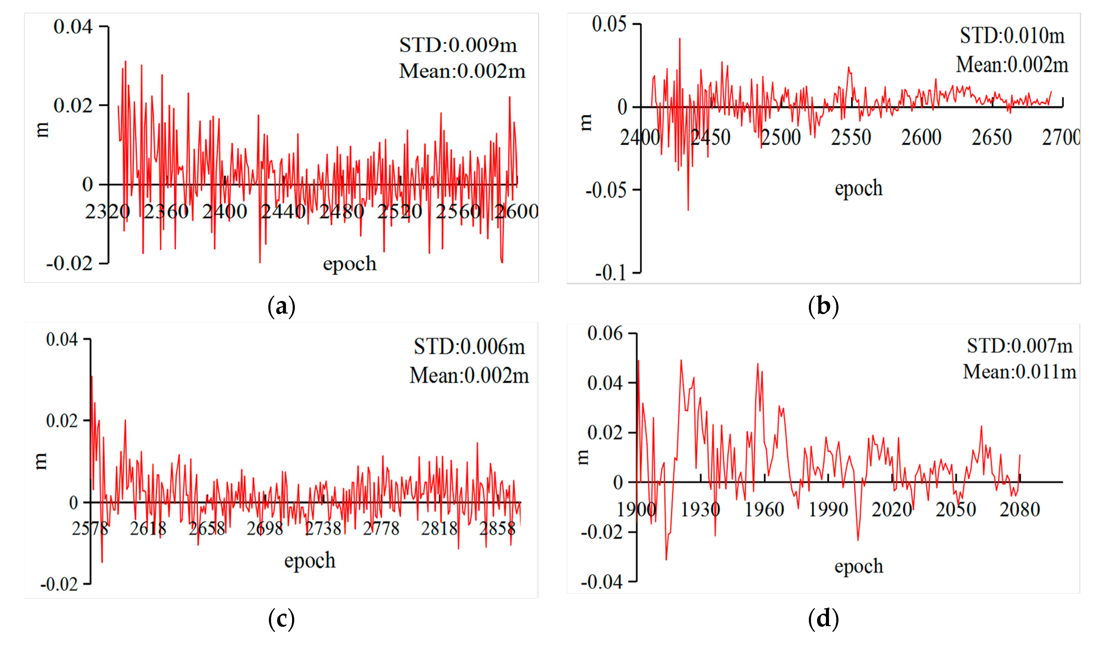
Figure 4, the errors of the predicted ionospheric delays are below 0.02 m as time increases, which can meet the requirements of the cycle-slip detection and repair.
The simulation experiments verified the accuracy of the improved cycle-slip detection and repair algorithm proposed in this study. The orbit determination should be further tested to demonstrate the reliability of the proposed algorithm. However, given the data quality and limited data sources, the observations from multiple tracking networks must be fully applied to improve the accuracy of the parameter estimation. In the following section, two methods were used to effectively utilize the observations from iGMAS and MGEX tracking networks.
4. BDS-3 Orbit Determination and Its Accuracy Analysis
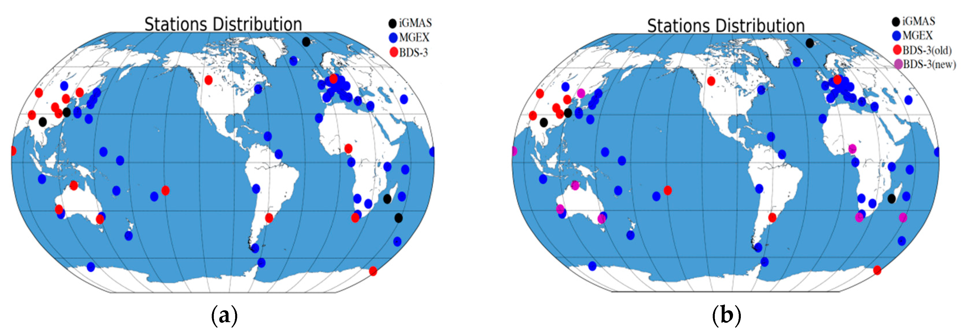
In this study, the BDS-3 experimental satellite orbit determination was conducted from DOY 154, 2016 to DOY 149, 2017 with iGMAS and MGEX observations. The distribution of tracking stations is presented in
Figure 7a, where the types of stations are represented by different colors. A total of 16 iGMAS (nine of them contain BDS-3 observations) and 54 MGEX stations were used at the beginning of the orbit determination. However, numbers of stations containing BDS-3 observations increased to 17 at the end of the experiment given the equipment update and network extension of the iGMAS.
Figure 7b shows the distribution of stations, where the BDS-3 tracking stations are presented with magenta. The parameter configurations and related models of orbit determination refer to [
15], in which the main parameters are listed in
Table 5. Moreover, the model used in used GPS orbit determination, e.g., for solar radiation pressure, were considered here as a reference.
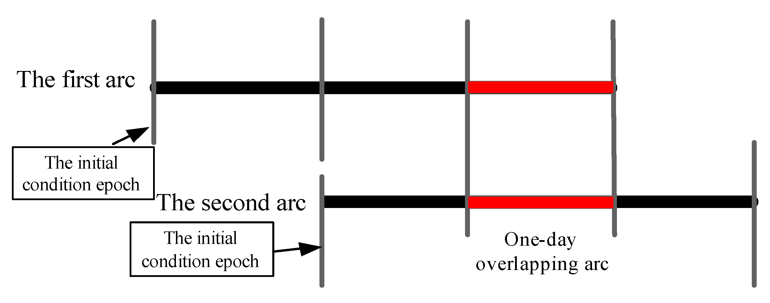
This study assessed the BDS-3 experimental satellite orbit based on the following experiments to adequately analyze its accuracy: (1) the 3D RMS of one-day overlapping arc errors based on two adjacent orbit determination processes, the scheme of which is displayed in
Figure 8; and (2) BDS-3 is equipped with laser retroreflector array, which can be used to check the orbit accuracy by SLR residuals.
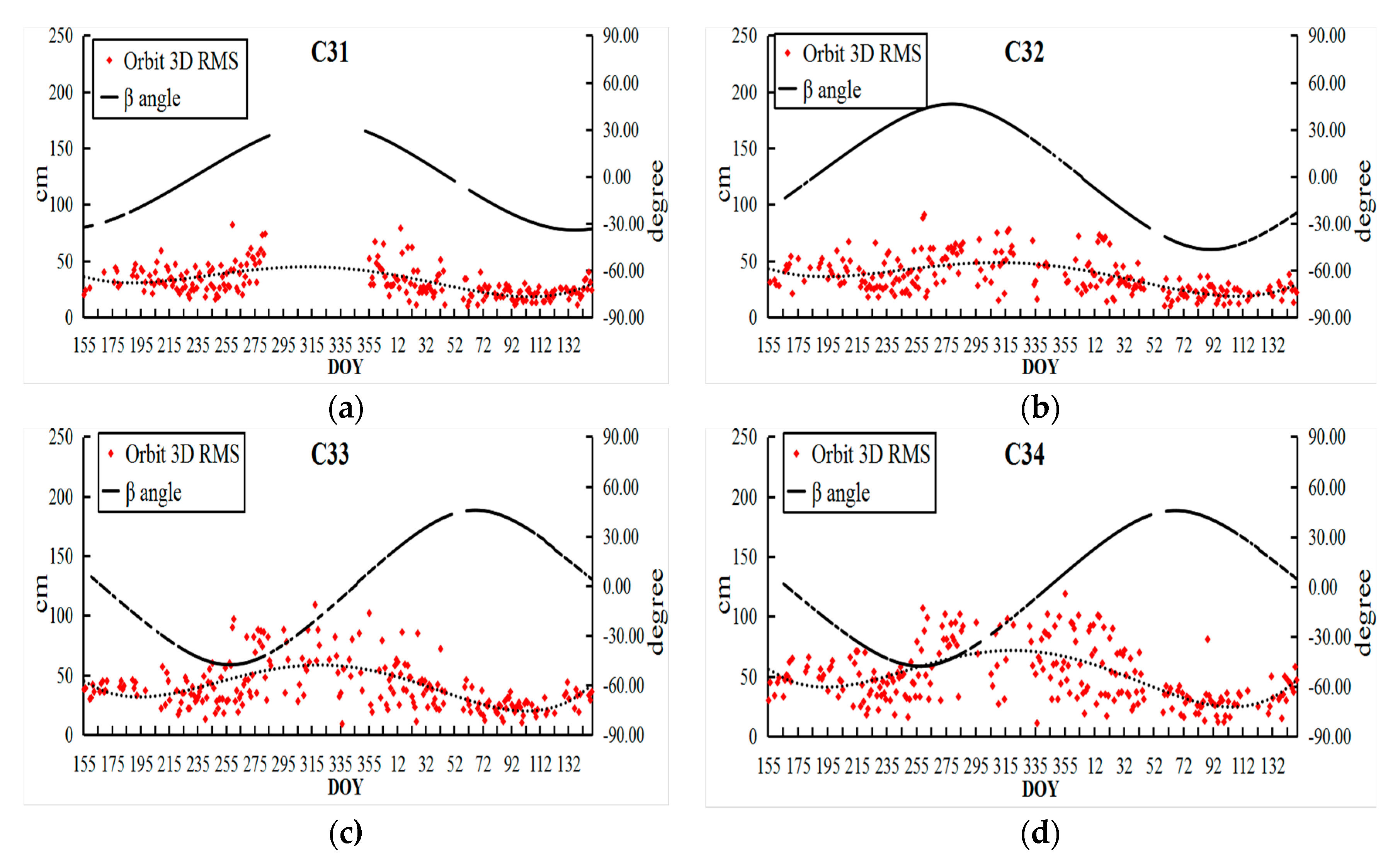
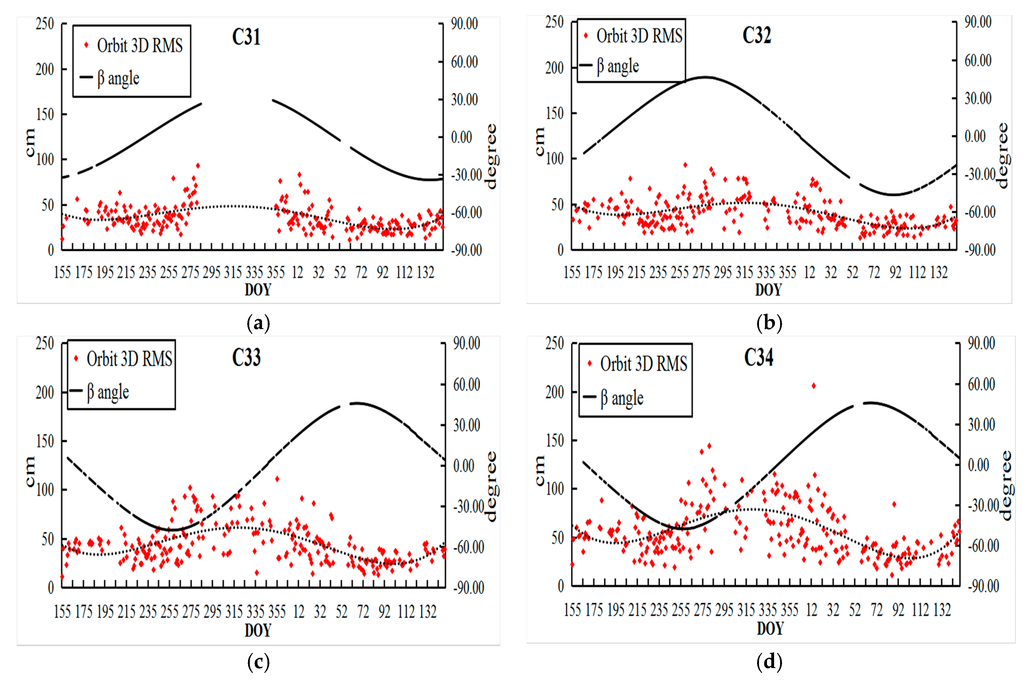
The overlapping arcs accuracy of two methods for BDS-3 (C31, C32, C33, and C34) orbit determinations are illustrated in
Figure 9 and
Figure 10 for the period DOY 155, 2016 until DOY 149 in 2017. The variations of the orbit accuracy were fitted by a trend line (dashed) in the results. In addition, the angles between orbital plane and Sun called β were also plotted in corresponding figures.
In
Figure 9 and
Figure 10, the accuracy of BDS-3 was worse at the end of 2016, while it became better in 2017 due to the update of the iGMAS tracking network. Moreover, it was found that the β angles were highly-correlated with the accuracy of the BDS-3, especially for IGSO (C31 and C32). Because the solar radiation pressure model of GPS was taken into the orbit determination, this is not suitable for the new-generation BeiDou satellites and should be refined in later studies.
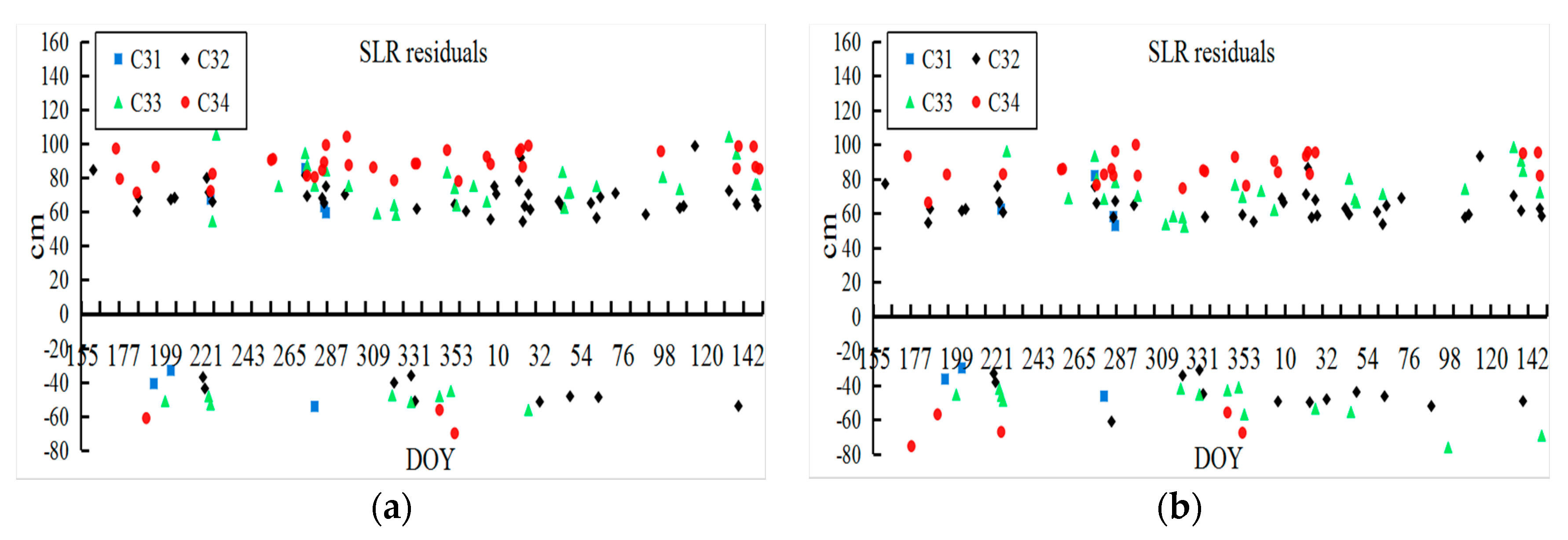
In addition, the SLR residuals of the two methods are shown in
Figure 11. The corresponding mean and RMS values of SLR residuals are presented in
Table 6 based on the one-year BDS-3 orbit determination to analyze the orbit accuracy by the NES and SS methods. Since the SLR data points of BDS-3 were insufficient, the trend of the SLR residuals could not be acquired accurately.
In the experiments, the 3D RMS of one-day overlapping arcs of BDS-3 (C31, C32, C33, and C34) based on the NES and SS are 31.0, 36.0, 40.3, and 50.1 cm and 34.6, 39.4, 43.4, and 55.5 cm, respectively. The RMS of SLR residuals of the NES and SS are 55.1, 49.6, 61.5, and 70.9 cm and 60.5, 53.6, 65.8, and 73.9 cm, respectively. In addition, the mean values of SLR residuals for the two methods are approximately equal, which could be caused by the different laser retroreflector arrays between BDS-2 and BDS-3. The experimental results showed that the NES is slightly better than the SS in BDS-3 orbit determination. Furthermore, the reason why the NES offers more accurate BDS-3 orbits can be explained as follows: (1) Due to the restriction of the number and distribution of BDS-3 tracking stations, the correlations between the BDS-3 orbit parameters and iGMAS stations related parameters are clearer. However, the SS method ignores the stochastic information of iGMAS parameters in the final parameter determination step; (2) The biases between different types satellites cannot be eliminated in SS, while the NES method takes the spatial seven-parameter transformation to reduce the difference of two normal equation. Moreover, the results in
Table 6 show that the mean and RMS values of SLR residuals are larger than the initial assessment results conducted in [
13]. It is suggested that a system error caused by the different SLR-related parameters (SLR retroreflectors) is included in the final results.
Then, one-month of observations (DOY 228–259, 2016) were selected to conduct the BDS-3 orbit determination with four schemes and further illustrate the reliability and advantages of the proposed methods. This study calculated the orbit accuracy of BDS-3 in four schemes according to orbit overlapping arc errors. The specific schemes are as follows:
- Scheme 1:
Based on the BDS-3 orbit determination using iGMAS observations, the traditional Turboedit was used, and the BDS-3 orbits were determined by one step (compared with SS, one step is widely used by GNSS data analysis centers [
35], which estimates all parameters in a single-step solution).
- Scheme 2:
Based on iGMAS observations, the improved cycle-slip detection and repair algorithm was used, and the BDS-3 orbits were acquired through one step.
- Scheme 3:
Based on iGMAS and MGEX observations, the improved cycle-slip detection and repair algorithm was used to determine the BDS-3 orbits through SS.
- Scheme 4:
Based on iGMAS and MGEX observations, NES based on the improved cycle-slip detection and repair proposed in this study was used to determine the BDS-3 orbits.
The SLR residuals of the BDS-3 orbit cannot be accurately determined because the limited SLR data within the experimental period. Therefore, this study only counted the discrepancy of overlapping arcs as illustrated in
Figure 8. Similarly,
Table 7 lists the corresponding orbit 3D RMS and improvement (compared with Scheme 1), in which Scheme 4 was considered as the optimal strategy. Moreover, the accuracy of the BDS-3 orbits obtained by Scheme 4 improved by 34.07%, 41.05%, 72.29%, and 74.33% for C31, C32, C33, and C34, respectively. However, the improvement of orbit accuracy using Scheme 2 was less distinct than Scheme 3 and Scheme 4, which indicated that the contribution of the improved cycle-slip detection and repair algorithm to the parameter estimation was less than the combination of different observation networks, given the fact that the combination offers a more reasonable global network structure. The orbit accuracy obtained using Scheme 3 was slightly worse than that of Scheme 4; this result is consistent with the theory discussed earlier. Furthermore, to analyze the reliability of the improved cycle-slip detection and repair algorithm, the data availability was taken into consideration based on the residuals of every epoch in Scheme 2. In
Table 8, the threshold was set as 4σ, where σ is the mean square error of observation residuals, to eliminate the observations with poor quality. From
Table 8, the improved algorithm enhanced the data availability from 12.90% to 20.46% compared with the traditional Turboedit approach.
5. Conclusions and Prospects
In this study, the BDS-3 experimental satellite’s precise orbit determination and the corresponding analyses of the results were conducted based on the iGMAS and MGEX networks. In the data processing, an improved cycle-slip detection and repair algorithm was proposed to overcome the disadvantages of the traditional Turboedit in the iGMAS data. From the analysis of observations, it is suggested that the new algorithm is reliable and efficient in improving the data availability of iGMAS observations and accuracy of the parameters related to BDS-3, which considers the correlation of ionospheric delays between adjacent epochs based on the polynomial prediction. Moreover, the improved algorithm preprocesses observations epoch-wise and can optimize the observations in real-time.
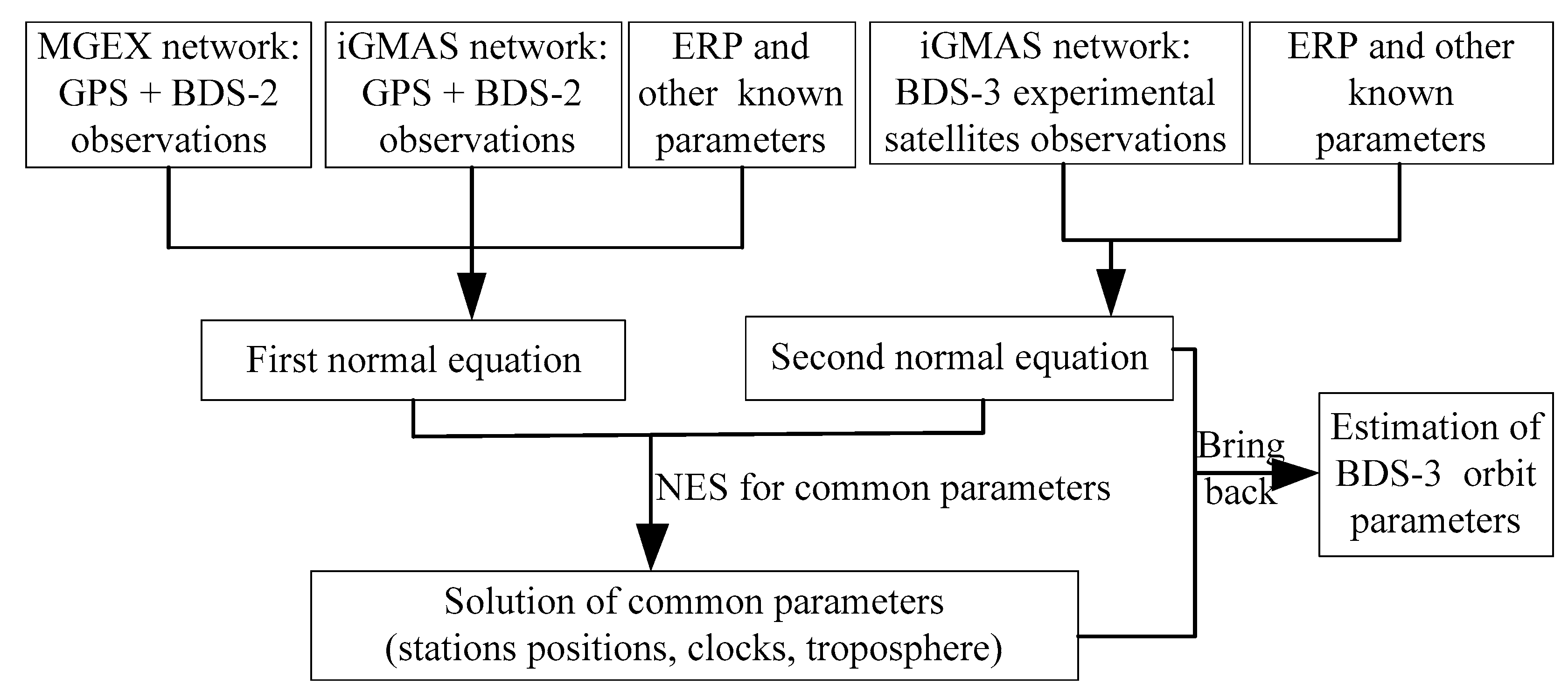
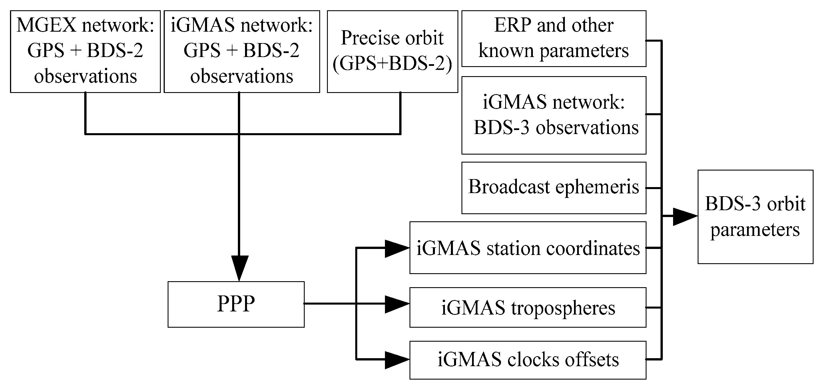
The insufficient BDS-3 observations caused by the tracking stations were the major factor for limiting its orbit accuracy. In this study, the MGEX observations were used to enhance the estimation of the iGMAS station-related parameters, which indirectly improved the accuracy of the BDS-3 orbit parameters. However, the observation types from the iGMAS for BDS-3 were B1 and B3, while MGEX mainly tracked B1 and B2 for BDS-2. Therefore, this study designed two BDS-3 orbit determination methods, namely, NES and SS, to achieve the combination of different observations. In NES, the common parameters were obtained through the Gaussian elimination method based on the normal equation from the BDS-3 orbit determination with iGMAS, and that of GPS and BDS-2 orbit determination with iGMAS and MGEX. However, SS was utilized to fix the iGMAS station-related parameters by the PPP network solution with GPS and BDS-2 observations. Then, the fixed parameters were assumed as the known parts in the BDS-3 orbit determination. Moreover, a matrix decomposition method was proposed in this study to improve the efficiency of the parameter estimation in NES.
One-year BDS-3 (C31, C32, C33, and C34) orbit determination based on the MGEX and iGMAS observations were conducted, and the corresponding orbit accuracy of four satellites were analyzed. The accuracy of BDS-3 was calculated from the discrepancy of the overlapping arcs and SLR residuals. Results showed that BDS-3 orbit accuracy obtained through the NES and SS were 31.0, 36.0, 40.3, and 50.1 cm and 34.6, 39.4, 43.4, and 55.5 cm, respectively. Meanwhile, the RMSs of the SLR residuals were 55.1, 49.6, 61.5, and 70.9 cm and 60.5, 53.6, 65.8, and 73.9 cm, respectively. The accuracy of the BDS-3 orbit was gradually improved by fitting the trend of overlapping arcs, which was mainly related to the increased number of BDS-3 stations in the iGMAS network. In addition, it was found that the orbit accuracy was highly-correlated with the β angle, especially for IGSO (C31 and C32), during the experimental period.
Four schemes of BDS-3 orbit determination were designed by one-month observations to fully illustrate the reliability and advantages of the improved strategies proposed in this study. The orbit accuracy and improvement of each scheme were calculated. Results showed that the NES based on the improved cycle-slip detection and repair was optimal for BDS-3 orbit determination compared with other schemes. The accuracy of the BDS-3 orbit improved by 34.07%, 41.05%, 72.29%, and 74.33%, for C31, C32, C33, and C34, correspondingly.
However, the limited tracking observations and unknown satellite parameters resulted in low accuracy in BDS-3. Therefore, the ISL and low Earth orbit satellites will be considered in the orbit determination to further improve the accuracy of BDS-3 orbit in the follow-up research tasks. Moreover, the application of precise BDS-3 orbits based on the new signals will be discussed as given in [
36,
37].


