Beamforming Design for Full-Duplex SWIPT with Co-Channel Interference in Wireless Sensor Systems


Abstract
1. Introduction
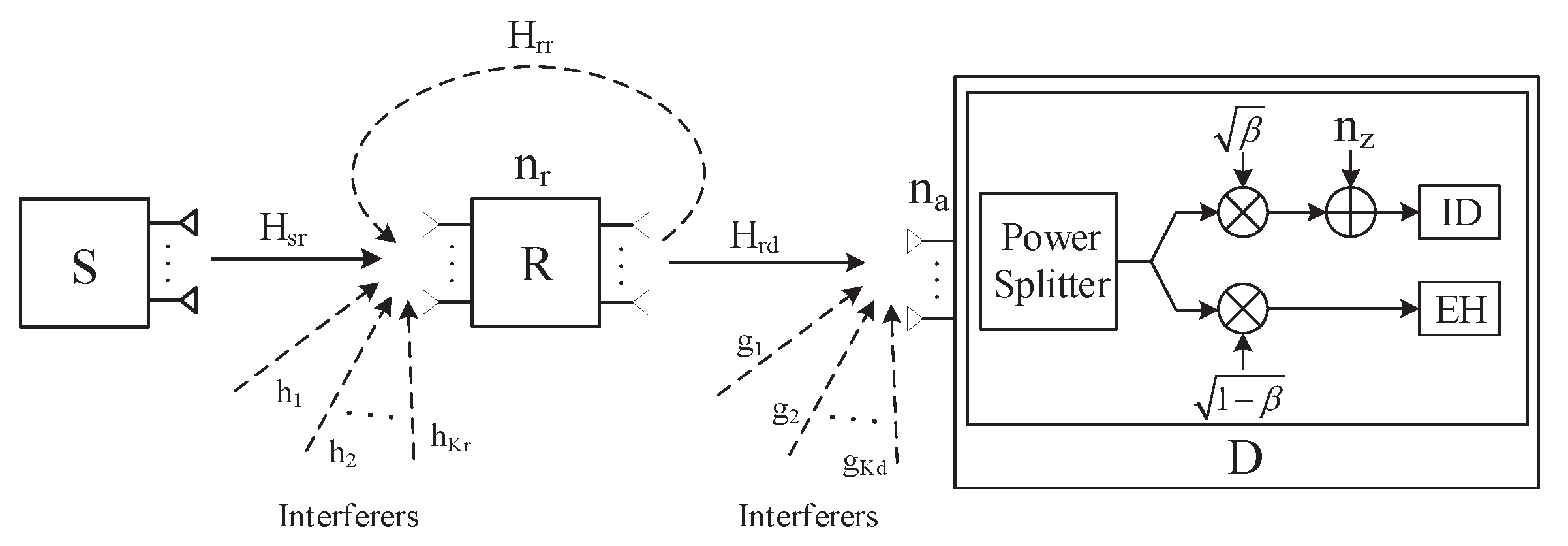
2. System Model
2.1. Node Deployment
2.2. Optimization Model
3. Scheme Design
3.1. Optimization of
- (i)
- ;
- (ii)
- ;
- (iii)
- .
3.2. Optimization of
3.3. Alternating Optimization Algorithm
| Algorithm 1 Alternating optimization algorithm based on SCA. |
| 1. Initialize Set and the initial beamforming matrix , . 2. Repeat
3. Until or |
3.4. Low-Complexity Design for
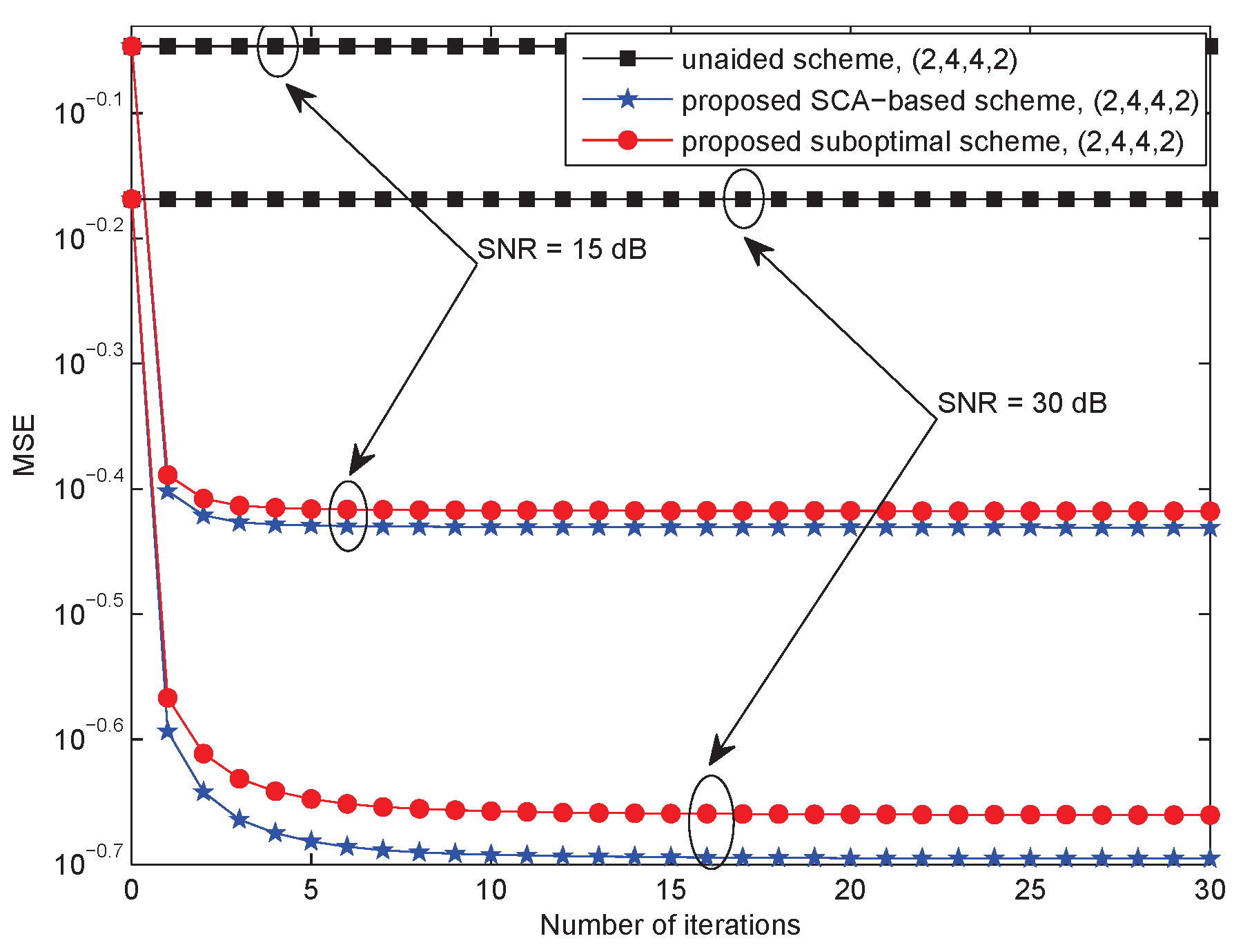
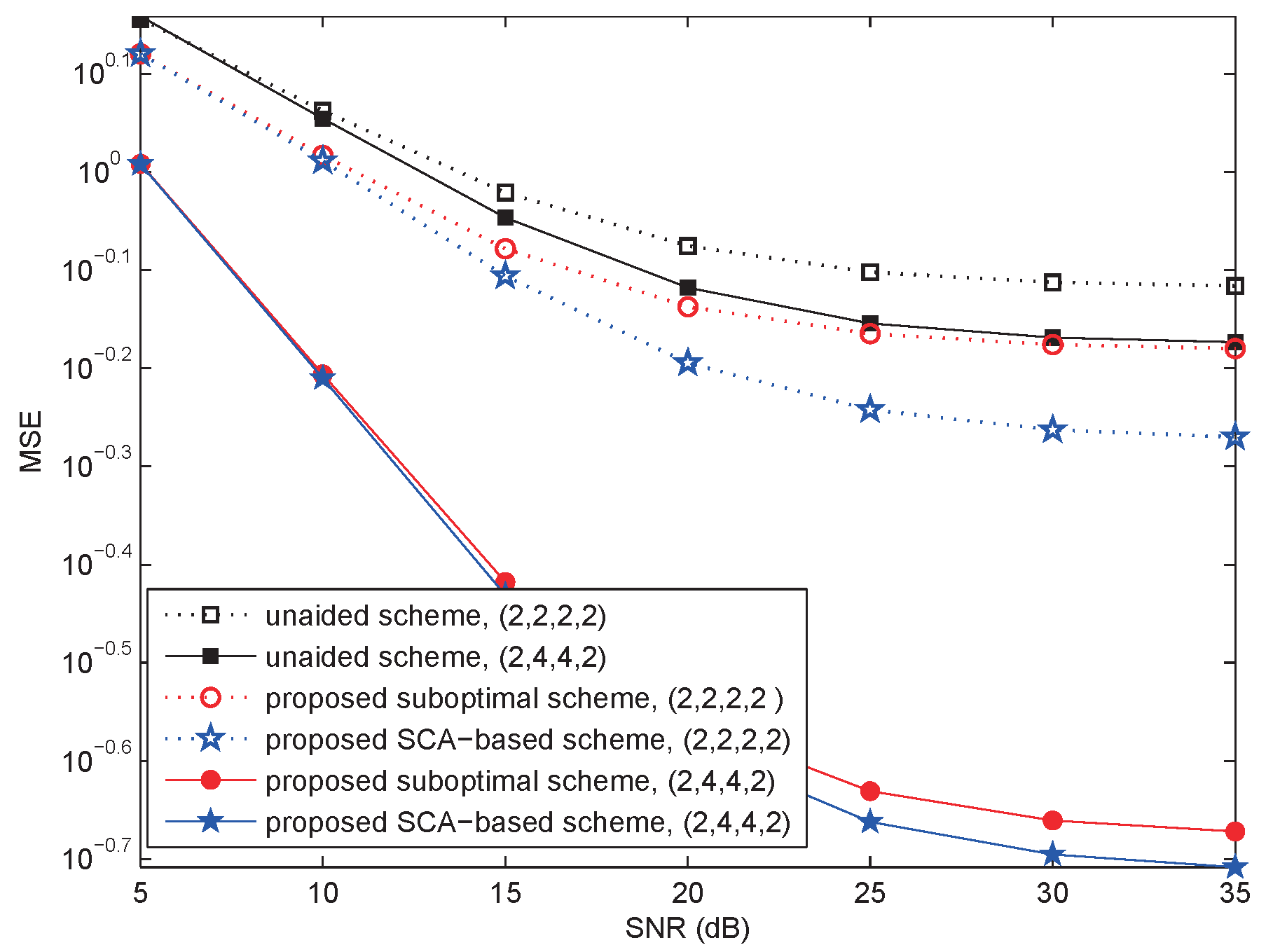
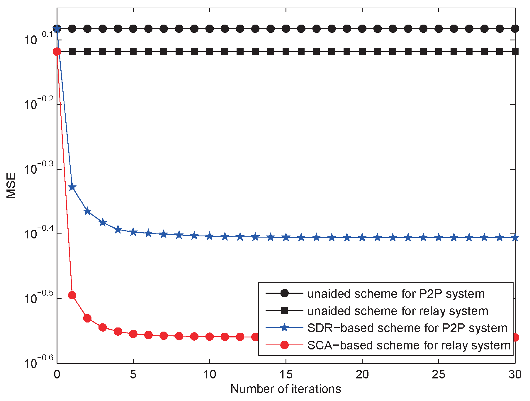
4. Numerical Results and Discussion
5. Conclusions
Author Contributions
Funding
Conflicts of Interest
Abbreviations
| WSN | Wireless sensor network |
| SWIPT | Simultaneous wireless information and power transfer |
| ZF | Zero-forcing |
| CSN | Cognitive sensor network |
| AF | Amplify-and-forward |
| PSR | Power splitting-based relaying |
| MIMO | Multiple-input multiple-output |
| TS | Time switching |
| PS | Power splitting |
| EH | Energy harvesting |
| ID | Information decoding |
| CCIs | Co-channel interferers |
| IFC | Interference channel |
| HD | Half-duplex |
| FD | Full-duplex |
| P2P | Point-to-point |
| MSE | Mean-squared-error |
| SCA | Successive convex approximation |
| AO | Alternating optimization |
| KKT | Karush–Kuhn–Tucker |
| CSI | Channel state information |
| AWGN | Additive white Gaussian noise |
| SOCP | Second-order cone programming |
Appendix A
Appendix B
References
- Lloyd, E.; Xue, G. Relay Node Placement in Wireless Sensor Networks. IEEE Trans. Comput. 2007, 56, 134–138. [Google Scholar] [CrossRef]
- Zhao, J.; Qiao, C.; Yoon, S.; Sudhaakar, R.S. Enabling Multi-Hop Communications through Cross-Layer Design for Hybrid WSNs with Transmit-Only Nodes. In Proceedings of the 2011 IEEE Global Telecommunications Conference (GLOBECOM 2011), Kathmandu, Nepal, 5–9 December 2011. [Google Scholar]
- Ciuonzo, D.; Buonanno, A.; D’Urso, M.; Palmieri, F.A. Distributed classification of multiple moving targets with binary wireless sensor networks. In Proceedings of the 2011 Proceedings of the 14th International Conference on Information Fusion (FUSION), Chicago, IL, USA, 5–8 July 2011. [Google Scholar]
- Rossi, P.S.; Ciuonzo, D.; Ekman, T. HMM-based decision fusion in wireless sensor networks with noncoherent multiple access. IEEE Commun. Lett. 2015, 19, 871–874. [Google Scholar] [CrossRef]
- Rossi, P.S.; Ciuonzo, D.; Kansanen, K.; Ekman, T. Performance analysis of energy detection for MIMO decision fusion in wireless sensor networks over arbitrary fading channels. IEEE Trans. Wirel. Commun. 2016, 15, 7794–7806. [Google Scholar] [CrossRef]
- Li, S.; Zhou, X.; Wang, C.; Yuan, D.; Zhang, W. Joint Transmit Power Allocation and Splitting for SWIPT Aided OFDM-IDMA in Wireless Sensor Networks. Sensors 2017, 17, 1–19. [Google Scholar] [CrossRef] [PubMed]
- Zhou, Z.; Zhou, S.; Cui, J.; Cui, S. Energy-Efficient Cooperative Communication Based on Power Control and Selective Single-Relay in Wireless Sensor Networks. IEEE Trans. Wirel. Commun. 2008, 7, 3066–3078. [Google Scholar] [CrossRef]
- Yu, H.; Zhang, Y.; Guo, S.; Yang, Y.; Ji, L. Energy Efficiency Maximization for WSNs with Simultaneous Wireless Information and Power Transfer. Sensors 2017, 17, 1–29. [Google Scholar] [CrossRef] [PubMed]
- Jiang, F.; Chen, J.; Swindlehurst, A.L.; López-Salcedo, J.A. Massive MIMO for Wireless Sensing With a Coherent Multiple Access Channel. IEEE Trans. Signal Process. 2015, 63, 3005–3017. [Google Scholar] [CrossRef]
- Shirazinia, A.; Dey, S.; Ciuonzo, D.; Rossi, P.S. Massive MIMO for Decentralized Estimation of a Correlated Source. IEEE Trans. Signal Process. 2016, 64, 2499–2512. [Google Scholar] [CrossRef]
- Ciuonzo, D.; Rossi, P.S.; Dey, S. Massive MIMO channel-aware decision fusion. IEEE Trans. Signal Process. 2015, 63, 604–619. [Google Scholar] [CrossRef]
- Wen, Z.; Liu, X.; Zheng, S.; Guo, W. Joint Source and Relay Design for MIMO Two-Way Relay Networks With SWIPT. IEEE Trans. Veh. Technol. 2015, 67, 822–826. [Google Scholar] [CrossRef]
- Wang, S.; Xia, M.; Wu, Y. Multicast Wirelessly Powered Network With Large Number of Antennas via First-Order Method. IEEE Trans. Wirel. Commun. 2018, 17, 3781–3793. [Google Scholar] [CrossRef]
- Wang, S.; Xia, M.; Huang, K.; Wu, Y. Wirelessly Powered Two-Way Communication With Nonlinear Energy Harvesting Model: Rate Regions Under Fixed and Mobile RelaySecure Multiple Amplify-and-Forward Relaying With Cochannel Interference. IEEE Trans. Wirel. Commun. 2018, 16, 8190–8204. [Google Scholar] [CrossRef]
- Tang, X.; Cai, Y.; Yang, W.; Yang, W.; Chen, D.; Hu, J. Secure Transmission of Cooperative Zero-Forcing Jamming for Two-User SWIPT Sensor Networks. Sensors 2018, 18, 1–12. [Google Scholar]
- Lu, W.; Lin, Y.; Peng, H.; Nan, T.; Liu, X. Joint Resource Optimization for Cognitive Sensor Networks with SWIPT-Enabled Relay. IEEE Trans. Comput. 2017, 17, 1–17. [Google Scholar] [CrossRef] [PubMed]
- Zhang, R.; Ho, C.K. MIMO Broadcasting for Simultaneous Wireless Information and Power Transfer. IEEE Trans. Wirel. Commun. 2013, 12, 1989–2001. [Google Scholar] [CrossRef]
- Park, J.; Clerckx, B. Joint wireless information and energy transfer in a two-user MIMO interference channel. IEEE Trans. Wirel. Commun. 2013, 12, 4210–4221. [Google Scholar] [CrossRef]
- Park, J.; Clerckx, B. Joint wireless information and energy transfer in a K-user MIMO interference channel. IEEE Trans. Wirel. Commun. 2014, 13, 5781–5796. [Google Scholar] [CrossRef]
- Gu, Y.; Aissa, S. RF-Based Energy Harvesting in Decode-and-Forward Relaying Systems: Ergodic and Outage Capacities. IEEE Trans. Wirel. Commun. 2015, 14, 6425–6434. [Google Scholar] [CrossRef]
- Chen, Y. Energy-Harvesting AF Relaying in the Presence of Interference and Nakagami-m Fading. IEEE Trans. Wirel. Commun. 2016, 15, 1008–1017. [Google Scholar] [CrossRef]
- Almradi, A.; Hamdi, K.A. The Performance of Wireless Powered MIMO Relaying With Energy Beamforming. IEEE Trans. Commun. 2016, 64, 4550–4562. [Google Scholar] [CrossRef]
- Hu, Z.; Yuan, C.; Gao, F. Maximizing Harvested Energy for Full-Duplex SWIPT System with Power Splitting. IEEE Access 2017, 5, 24975–24987. [Google Scholar] [CrossRef]
- Zhong, C.; Suraweera, H.A.; Zheng, G.; Krikidis, L.; Zhang, Z. Wireless Information and Power Transfer with Full Duplex Relaying. IEEE Trans. Commun. 2014, 62, 3447–3461. [Google Scholar]
- Okandeji, A.A.; Khandaker, M.R.A.; Wang, K.; Zheng, Z. Joint Transmit Power and Relay Two-Way Beamforming Optimization for Energy-Harvesting Full-Duplex Communications. In Proceedings of the 2016 Globecom Workshops (GC Wkshps), Washington, DC, USA, 4–8 December 2016. [Google Scholar]
- Wen, Z.; Liu, X.; Beaulieu, N.C.; Wang, R.; Wang, S. Joint Source and Relay Beamforming Design for Full-Duplex MIMO AF Relay SWIPT Systems. IEEE Commun. Lett. 2016, 20, 320–323. [Google Scholar] [CrossRef]
- Tsinos, C.G.; Berberidis, K. A Cooperative Uplink Transmission Technique with Improved Diversity–Multiplexing Tradeoff. IEEE Trans. Veh. Technol. 2015, 64, 2883–2896. [Google Scholar] [CrossRef]
- Tsinos, C.G.; Berberidis, K. Multi-antenna cooperative systems with improved diversity multiplexing tradeoff. In Proceedings of the 2012 IEEE Wireless Communications and Networking Conference (WCNC), Shanghai, China, 1–4 April 2012; pp. 1093–1097. [Google Scholar]
- Tsinos, C.G.; Berberidis, K. An adaptive beamforming scheme for cooperative wireless networks. In Proceedings of the 2009 16th International Conference on Digital Signal Processing, Santorini, Greece, 15 January 2009. [Google Scholar]
- Xue, J.; Biswas, S.; Cirik, A.C.; Du, H.; Yang, Y.; Ratnarajah, T.; Sellathurai, M. Transceiver Design of Optimum Wirelessly Powered Full-Duplex MIMO IoT Devices. IEEE Trans. Commun. 2018, 66, 1955–1969. [Google Scholar] [CrossRef]
- Boyd, S.; Vandenberghe, L. Convex Optimization; Cambridge University Press: Cambridge, UK, 2004. [Google Scholar]
- Mehanna, O.; Huang, K.; Gopalakrishnan, B.; Konar, A. Feasible Point Pursuit and Successive Approximation of Non-Convex QCQPs. IEEE Signal Process. Lett. 2015, 22, 804–808. [Google Scholar] [CrossRef]
- Wang, G.; Chen, H.; Li, Y.; Jin, M. On Received-Signal-Strength Based Localization with Unknown Transmit Power and Path Loss Exponent. IEEE Wirel. Commun. Lett. 2012, 1, 536–539. [Google Scholar] [CrossRef]
- Wang, C.; Chen, H.; Yin, Q.; Feng, A.; Molisch, A.F. Multi-User Two-Way Relay Networks with Distributed Beamforming. IEEE Trans. Wirel. Commun. 2011, 10, 3460–3471. [Google Scholar] [CrossRef]
- Wen, Z.; Liu, X.; Chen, Y.; Wang, R.; Xie, Z. Joint Transceiver Designs for Full-Duplex MIMO SWIPT Systems Based on MSE Criterion. China Commun. 2016, 13, 79–85. [Google Scholar] [CrossRef]


© 2018 by the authors. Licensee MDPI, Basel, Switzerland. This article is an open access article distributed under the terms and conditions of the Creative Commons Attribution (CC BY) license (http://creativecommons.org/licenses/by/4.0/).
Share and Cite
Liu, X.; Jia, Y.; Wen, Z.; Zou, J.; Li, S. Beamforming Design for Full-Duplex SWIPT with Co-Channel Interference in Wireless Sensor Systems. Sensors 2018, 18, 3362. https://doi.org/10.3390/s18103362
Liu X, Jia Y, Wen Z, Zou J, Li S. Beamforming Design for Full-Duplex SWIPT with Co-Channel Interference in Wireless Sensor Systems. Sensors. 2018; 18(10):3362. https://doi.org/10.3390/s18103362
Chicago/Turabian StyleLiu, Xiaoqing, Yinglin Jia, Zhigang Wen, Junwei Zou, and Shan Li. 2018. "Beamforming Design for Full-Duplex SWIPT with Co-Channel Interference in Wireless Sensor Systems" Sensors 18, no. 10: 3362. https://doi.org/10.3390/s18103362
APA StyleLiu, X., Jia, Y., Wen, Z., Zou, J., & Li, S. (2018). Beamforming Design for Full-Duplex SWIPT with Co-Channel Interference in Wireless Sensor Systems. Sensors, 18(10), 3362. https://doi.org/10.3390/s18103362