1. Introduction
As global satellite navigation systems (GNSSs) play an increasingly important role in society and industry, the security of these systems is a crucial component. Intentional and unintentional spoofing interference affects normal use of navigation and timing terminals. Unlike jamming, the goal of spoofing is to take control of the user receiver. The receiver captures the spoofing signal and uses it for the calculation of an incorrect positioning. In [
1], the authors analyzed the vulnerability of the satellite signal and the GNSS to attacks, illustrating how the spoofing signal enters and takes over the receiver. To facilitate a threat analysis, the authors divided the spoofing threat into three categories: simplistic, intermediate and sophisticated spoofing attacks [
2]. In addition to these three categories, there is another case: meaconing. Meaconing is the interception and replay of navigation signals on the received frequency, typically with a power higher than the original signal, to confuse the navigation terminal [
3].
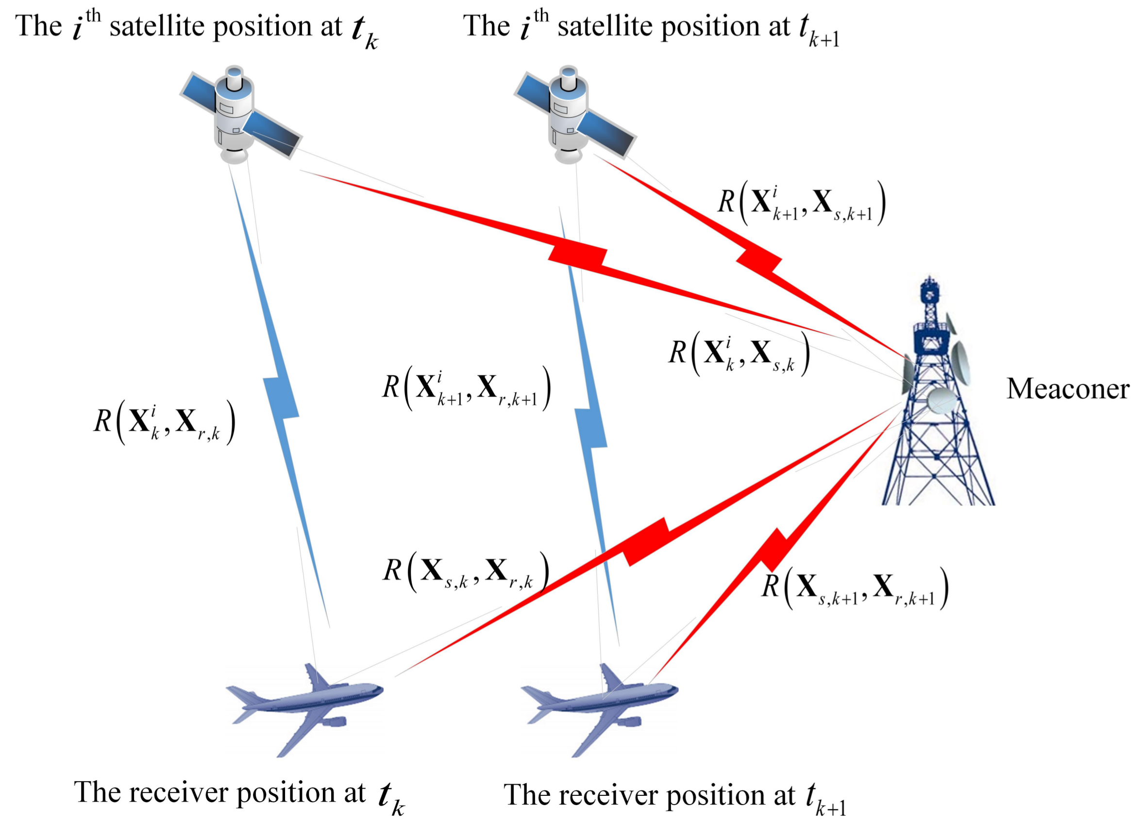
The main form and the purpose of a spoofer is to generate a similar and false satellite signal and make the receiver capture it. The spoofer is defined as a system containing three elements: the receiving antenna, the spoofing signal generator and the transmitting antenna. The receiving antenna receives the signal and inputs it into the spoofing signal generator. Then, the generator generates the spoofing signal, which has the same form as the satellite signal according to the input and the spoofing interference intention and is finally transmitted by the transmitting antenna. The signal input to the generator and the signal output from the generator are not the same, but are similar. The main form of the meaconer is to delay the transmission of the real signal by the delay module. A meaconer contains the same three elements as the spoofer; however, the meaconer has a signal transponder with a delay module instead of the spoofing signal generator. The whole process can be described as: the receiving antenna receives the signal and inputs it into the signal transponder, and the signal is then transmitted by the transmitting antenna after a certain delay. The signal input into the transponder and the signal output from the transponder are the same. The structure of the signal in this spoofing scenario is not changed. Compared with the spoofer, meaconing has the advantage that it is easier to implement and has a lower cost. The coarse/acquisition code (C/A code) of the satellite signal is open and transparent, and its structure is well known to the public. Therefore, the spoofing signal, which is very similar to the real satellite navigation signal, can mislead the receiver from the correct position. The precision code (P code) is encrypted and cannot be simulated easily. Even so, meaconing still can use it by the time delay module.
For spoofing interference, the spoofer should first destroy the connection between the receiver and the real signal and should then make the receiver capture the spoofing signal, preferably by a higher signal power than the normal one. In [
4], the authors point out that the tracking of the real signal can be destroyed as long as the power of the spoofing signal is at least four decibels (dB) higher than the real signal in the condition that the pseudo-code rate difference between the real signal and the spoofing signal is 1/3 Hertz (Hz) and the receiver’s coherent accumulated time is 1 ms. To suppress spoofing interference, the existence of the spoofing signal must first be accurately detected. Previous detection technologies mainly focused on signal distortion detection, by considering the signal power [
5,
6], the spatial distribution properties [
7,
8] and by observing the change rates of ranges and the clock offset/drifts [
1]. The signal power is influenced by many factors during transmission, and transient power increase does not mean the spoofing signal exists.
Spoofing interference can be simple or complex:
Simplistic spoofing attacks and meaconing can be regarded as “simple spoofing”. This “simple spoofing” is defined as a non-overlapped spoofing scenario. The main characteristic of this kind of spoofing is that the correlation peak of the spoofing pseudo-random noises (PRNs) is not overlapped with that of the authentic ones. This attack is usually generated by a hardware simulator or replayed by a signal transponder. An effective way to spoof a receiver in a non-overlapped scenario is to first jam and make the receiver lose its lock on the real signal and instead capture the spoofing signal [
9]. In this scenario, the spoofing signal appears as a noise and only affects the effective carrier noise power ratio (C/No). For example, in the simulation scenario of the “Beidou Open Laboratory test” in
Section 3, the signal is switched from the real to the spoofing signal with an absolute power advantage. Another effective way to spoof a receiver in a non-overlapped scenario is that the receiver enters an area that the satellite signal cannot cover, then the signal is generated through the simulator or replayed through the transponder to achieve spoofing. In this case, even if the value of C/No is lower than that of the real signal, the spoofing signal can still be captured by the receiver. In this scenario, the value of C/No is mainly affected by the transmitting power. The simulation scenario of the “university test” in
Section 3 is an example of this case.
The simulation scenarios of “the Texas spoofing test battery” used in this paper are more complex and can be regarded as “complex spoofing”. The “complex spoofing” is defined as overlapped spoofing scenarios. In an overlapped spoofing attack, the correlation peak of the spoofing signals and the real signals overlap, and this interaction misshapes the correlation peak. This kind of spoofing attack is generated by a receiver-based spoofing generator where the spoofer knows the current time, the observable satellites and the location and signal parameters of the target receiver. The real signal is separated from the composite signal (which is the overlap between the real signal and the spoofing signal) by a small power advantage to realize the signal switch. This kind of spoofing is harder to detect.
For simple spoofing, some related methods in [
1] are valid. However, for complex spoofing, these methods become invalid.
Current research focuses on using the antenna array method [
10], the receiver pseudorange or carrier phase difference [
11,
12], the correlation method [
13,
14], the inertial aided method [
15,
16] or the hypothesis testing method [
17,
18]. The antenna array method needs more than one antenna. Its detection performance is affected by the baseline length between the antennas. When there is only one single receiver or one single antenna, such a difference method cannot be used. The inertial aided method has some disadvantages. First, inertial devices are needed, and this increases the cost of the whole navigation system. Second, inertial navigation involves error accumulation over time. This makes it effective over a short period, but invalid over longer periods. There are also some studies on the hardware of the receiver needed to detect the signal [
19,
20]. All hardware-based methods require a change of the structure of existing receivers. Signal encryption is also a scheme to avoid spoofing interference, which is analyzed in [
21]. However, the implementation of this solution requires a comprehensive and systematic modification from satellite to receiver, which is not feasible in a short time. If users want to use the signal, permission is needed from the operator. Furthermore, as meaconing does not change the signal structure, the scheme of signal encryption cannot effectively suppress meaconing.
In addition, some crossing methods are proposed. In Ref. [
22], the authors proposed a method to monitor the spoofing signal based on machine learning and signal processing. Other methods can also detect spoofing signals to a certain extent, but still have limitations. Considering that some of such methods are complementary in spoofing detection, the authors adopted information fusion in combination with multiple spoofing detection strategies to improve the detection performance [
23]. The information fusion method is useful, but requires more hardware and software to realize the different detection methods and requires more time to finish the signal processing. The performance of the fusion algorithm determines the effectiveness of detection. In Ref. [
24], the authors proposed a network monitoring mechanism based on the time difference of arrival properties between spoofing and authentic signals. This network contains several receivers and one central processing component. From the simulation, we can see that the detection performance is influenced by the distance between the receiver and the central processing component. This structure is better suited for static testing.
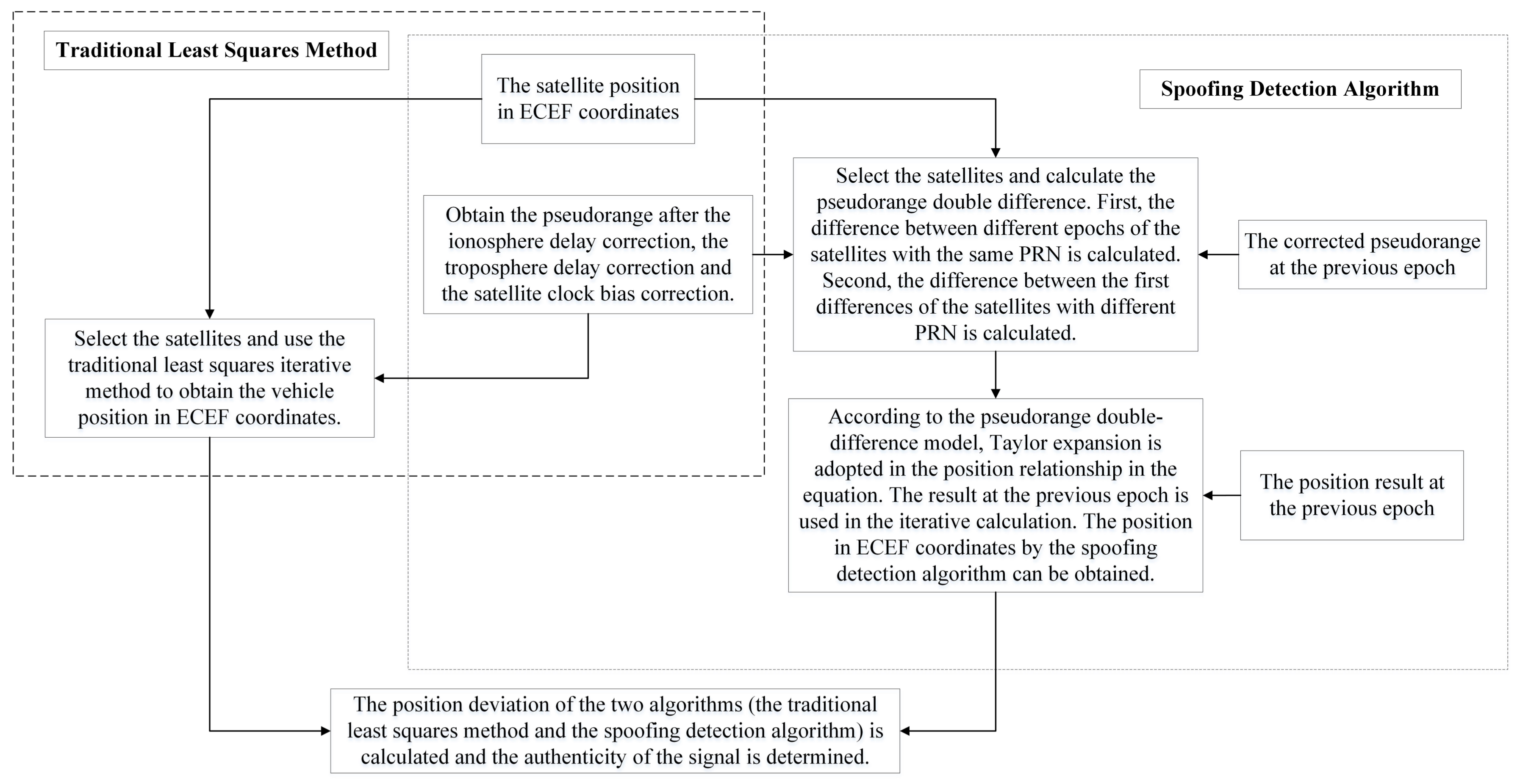
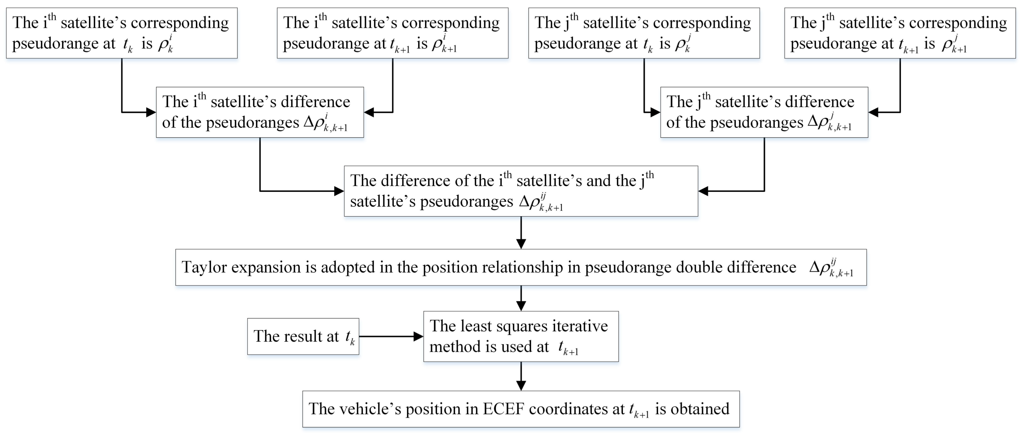
If a single receiver can be used to implement detections, the disadvantages mentioned above can be overcome. The motivation of this paper is to use a single receiver or a single antenna to detect meaconing, simplistic and intermediate spoofing attacks by pseudorange differences. The main contributions of this paper can be summarized as follows: (1) we build the signal pseudorange model based on the signal transmission path; (2) a novel spoofing detection algorithm is proposed based on the pseudorange model, which only needs one single receiver and does not require changing the hardware; (3) we validate the proposed algorithm on real experiments, showing its effectiveness and simplicity in real engineering applications. The hardware of the receiver does not need to be changed, and no additional auxiliary equipment is required. This is the advantage compared with other algorithms. The authenticity of the signal can be confirmed by comparing the result of the proposed spoofing detection algorithm with the result of the traditional least squares method. The paper is organized as follows:
Section 2 gives the theoretical analysis of a single receiver against the spoofing signal;
Section 3 describes three different test datasets, which are used to validate the algorithm performance;
Section 4 concludes the paper.
3. Simulation Tests
To verify the feasibility and effectiveness of the algorithm, different kinds of test datasets, including the university test dataset, the Beidou Open Laboratory test dataset and the Texas spoofing test battery (TEXBAT), are used in the simulation. We generated the first two datasets at our university and Beidou Open Laboratory, respectively, and the TEXBAT comprised the only public spoofing test datasets published by The University of Texas at Austin [
26,
27,
28,
29]. The data generation of these datasets is described in the following subsections. The performance of the algorithm is also verified in the dynamic whole-time duration position spoofing scenario. In all spoofing scenarios, all satellites are spoofed, and there is only one spoofer. Other characteristics of different scenarios are summarized in
Table 1. The false alarm rate and the missed detection rate in each scenario are calculated. The false alarm rate indicates the probability that the algorithm misjudges the real signal as the spoofing one. The missed detection rate indicates the probability that the algorithm misjudges the spoofing signal as the real one.
3.1. University Test
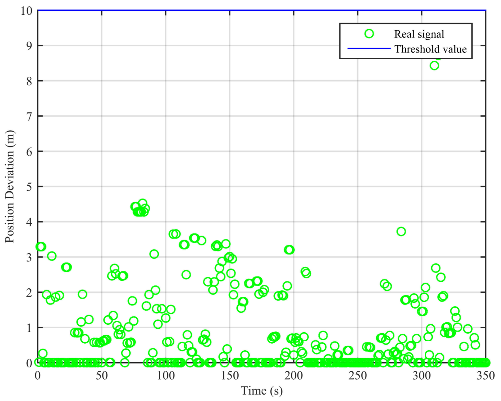
In this scenario, the receiver is in a static state first, and it receives the real signal. This process lasts about 80 s. Then, the signal transponder is turned on. The receiver is held by hand and approaches the signal transponder’s transmitting antenna slowly. This process is repeated twice and lasts about 100 s. We adopt the algorithm proposed in this paper and the traditional least squares method to analyze the collected data; the result is shown in
Figure 4.
From
Figure 4, we can see that the position deviations are smaller than the threshold value when the signal is real. When the signal transponder is turned on, the receiver starts to receive the replayed signal, and the position deviations start to increase and become larger than the threshold value. Based on these differences, we can determine the existence of the spoofing signal. The false alarm rate when the signal is real is 0%, and the missed detection rate when the signal is spoofing is 18%. The missed detections mainly occur within the short period after the signal is switched from real to spoofing. In this period, the position deviations caused by the spoofing signal are smaller than the threshold value.
3.2. Beidou Open Laboratory Test
To further verify the effectiveness of the algorithm, we conducted Experiment No. 2 in Beidou Open Laboratory. We used the antenna on the roof of the building to introduce the satellite’s signal into the room and assumed this signal to be real. The signal is input into the spoofing signal simulator, and the spoofing signal is output after the computer calculation. The output spoofing signal from the simulator moves circularly. The receiver is adopted in the whole duration. In this duration, the signal is real at first, and this process lasts about 90 s. Then, the spoofing signal simulator is turned on. The absolute power advantage guarantees that the receiver can receive the spoofing signal. The circular motion signal is then acquired. This process lasts about 135 s. Finally, the simulator is turned off, and the signal becomes real. This process lasts about 90 s.
We apply the traditional least squares method and the spoofing detection algorithm to the datasets and use (−2,185,955.407, 5,181,417.961, 2,999,272.014) as a reference point for coordinate transformation in the results shown in
Figure 5.
From
Figure 5, we can see that, for the real signal, the results of the two algorithms are basically the same. For the spoofing signal with circular motion, the difference of the results of the two algorithms is obvious. In
Figure 6, we can see that the position deviations in the first segment and the third segment are always small. The position deviations perform a significant change and remain large when the signal is switched from real to spoofing. These differences can help us to validate the signal authenticity. The false alarm rate when the signal is real is 2.91%, and the missed detection rate when the signal is spoofing is 2.04%.
3.3. The Texas Spoofing Test Battery
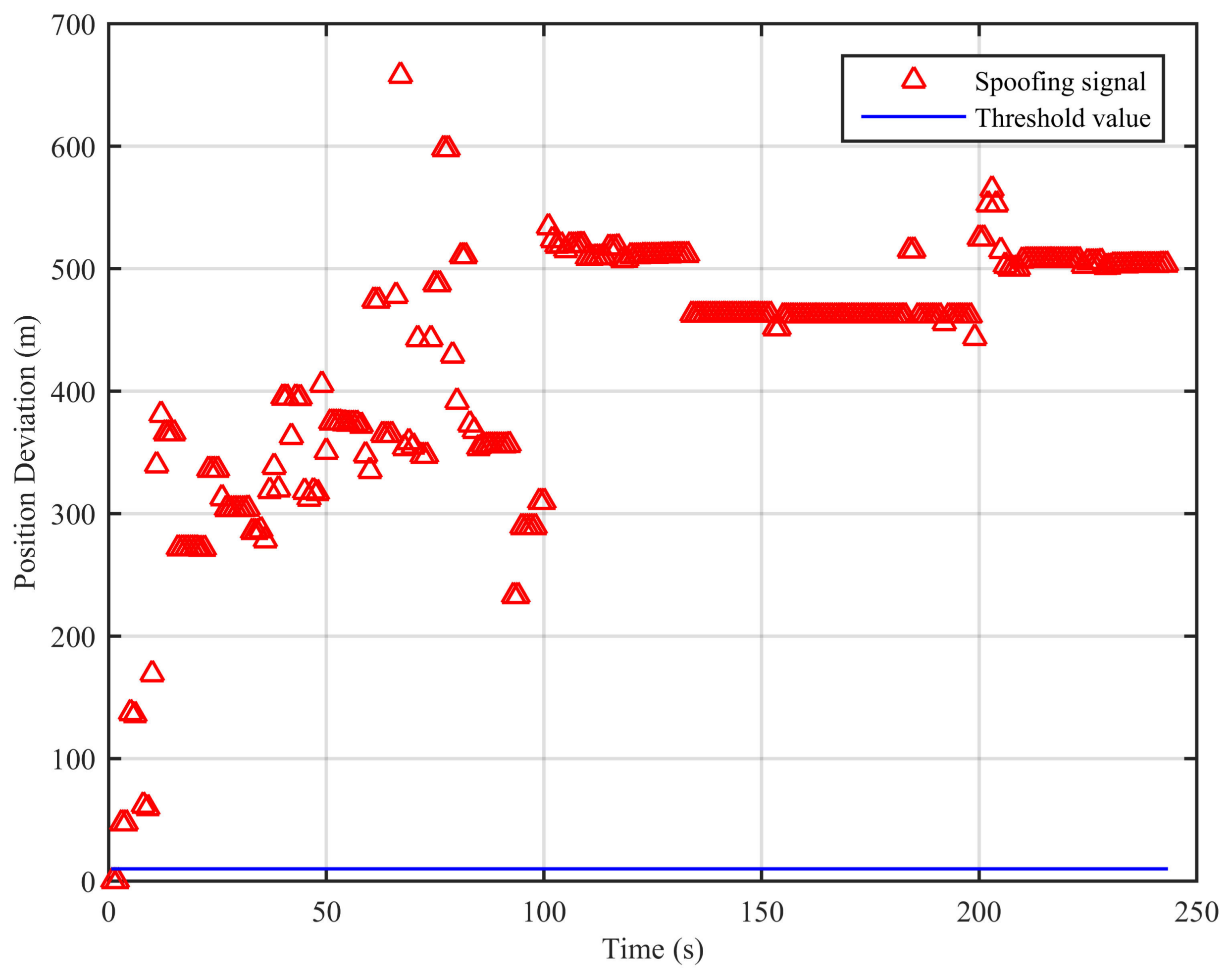
Finally, we adopt the only public spoofing test datasets, the Texas spoofing test battery (TEXBAT), to verify the detection performance of the algorithm. This involves eight separate spoofing scenarios and two clean scenarios. In this paper, we mainly focus on the positioning terminal. Therefore, for the spoofing experiments, we adopt the static position spoofing scenario and the dynamic position spoofing scenario. As a reference, we also adopt the two clean scenarios, which are the clean static scenario and the clean dynamic scenario. The remaining five datasets are the static or dynamic time spoofing scenarios and the signal switch scenario. Time spoofing scenarios focus mainly on the timing terminal.
In the clean static scenario, the receiver is placed on the roof of the Aerospace Engineering Building at the University of Texas to receive and record the real signal. In the clean dynamic scenario, the receiver platform is dynamic rather than static. The clean dynamic dataset was originally recorded by an antenna on a traveling vehicle. The static position spoofing scenario is based on the clean static scenario. The static signal is real in the first segment (around 170 s). Then, the receiver captures the spoofing signal with the power advantage of 0.4 dB higher than the real one. The spoofing signal slowly drives the receiver off the real position, and the ultimate bias is an offset of 600 m in the Z direction. In the dynamic position spoofing scenario, which is based on the clean dynamic scenario, the receiver is in a dynamic state. The signal is real at first. The spoofing signal slowly drives the receiver off the real position with a 0.8-dB power advantage in about 100 s. The ultimate bias is also an offset of 600 m in the Z direction.
For the TEXBAT datasets, we replay them with National Instruments (NI) equipment (NI equipment model numbers: NI PXIe-5450: 400 MS/s In-phase/Quadrature (I/Q) Signal Generator, NI PXIe-5611: I/Q Vector Modulator, NI PXI-5652: Radio Frequency (RF) Signal Generator) at Shanghai Advanced Research Institute, Chinese Academy of Sciences. The traditional least squares method and the spoofing detection algorithm proposed in this paper are used in the experiments.
Figure 7,
Figure 8,
Figure 9 and
Figure 10 show the position deviations of the two algorithms in the clean static scenario, the clean dynamic scenario, the static position spoofing scenario and the dynamic position spoofing scenario, respectively.
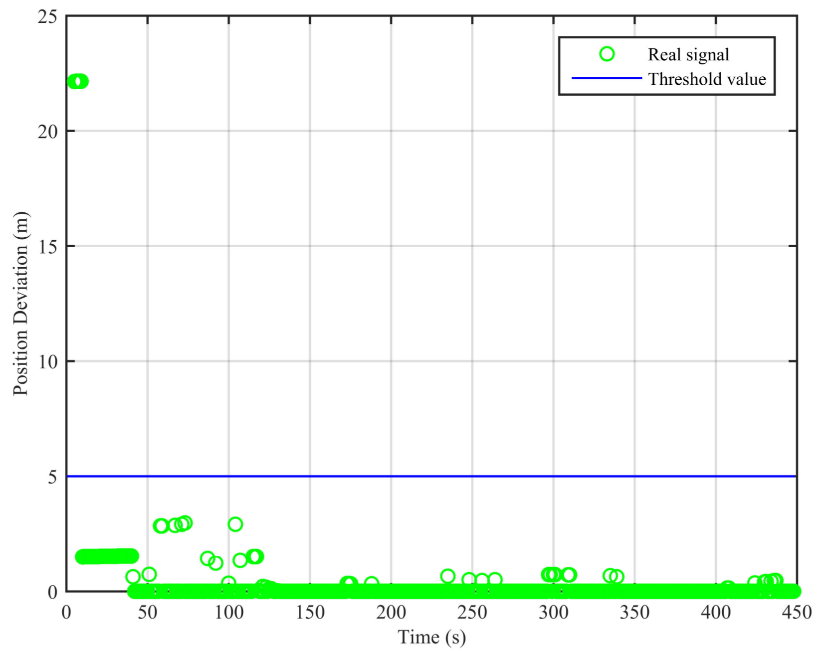
As can be seen from
Figure 7, the real signal is received in the clean static scenario, and the position deviations are always small. The false alarm rate when the signal is real is 1.12%. The false alarms mainly occur at the beginning, due to the code smoothing process embedded in the receiver. In
Figure 8, the real signal is received in the clean dynamic scenario. Though the position deviations in
Figure 8 are larger than those in
Figure 7, no big jump occurs in the whole duration. The false alarm rate when the signal is real is 0%. In
Figure 9 and
Figure 10, we can also observe that there exist obvious jumps in the position deviations of the two algorithms when the signal is switched from real to spoofing and that these jumps remain in the following duration. In the static position spoofing scenario, the false alarm rate when the signal is real is 0%, and the missed detection rate when the signal is spoofing is 1.55%. In the dynamic position spoofing scenario, the false alarm rate when the signal is real is 8%, and the missed detection rate when the signal is spoofing is 2.57%.
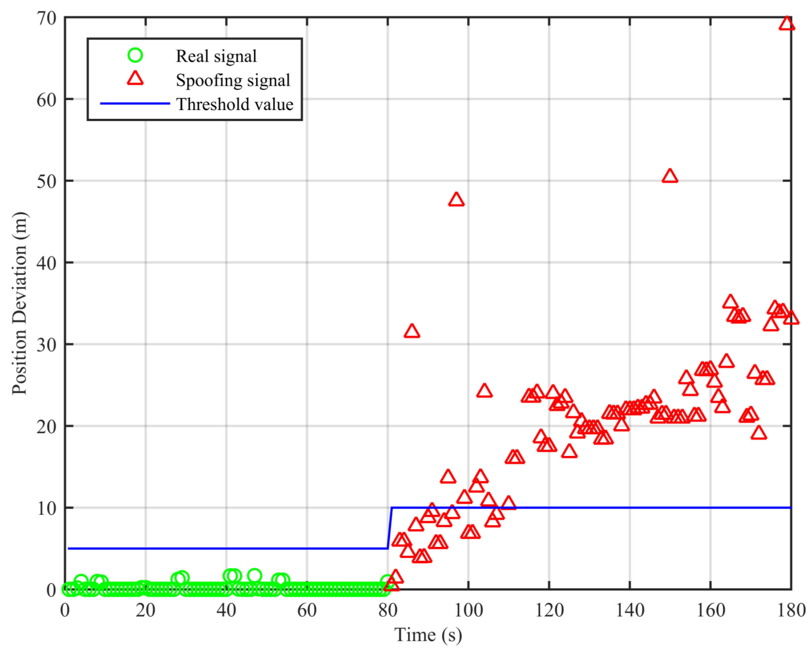
3.4. Dynamic Whole-Time Duration Spoofing Scenario
Further, we select the spoofing part of the dynamic position spoofing scenario in the TEXBAT datasets to construct the dynamic whole-time duration spoofing scenario to verify the performance of the algorithm. The simulation results are shown in
Figure 11.
The traditional least squares method’s result at the first epoch is used as the initial value in the calculation. From
Figure 11, we can see that the position deviations are larger than the threshold, and this indicates the existence of the spoofing signal. In this scenario, the missed detection rate when the signal is spoofing is 0.82%. This proves that the proposed spoofing detection algorithm is effective for the dynamic whole-time duration position spoofing scenario.
For the spoofing scenarios, the positions obtained by the traditional least squares method and the spoofing detection algorithm are different, and the position deviations will always be larger than the threshold value as long as the spoofing signal exists. The authenticity of the signal can then be determined. The spoofing detection algorithm’s results do not represent the receiver’s real position, thus the position deviations do not represent the position bias caused by the spoofing signal. Therefore, we cannot see the effect of the 600-m offset. If it is only solved by the traditional least squares method, we can observe that the receiver is slowly driven by the spoofing signal and reaches its final offset of 600 m.
3.5. Comparison with Other Methods
To further evaluate the performance of the algorithm, we select the related methods (range rates jump detection, C/No jump detection, the clock offset and the clock drift jump detection) from [
1] in the simulation, and the results are shown in
Figure 12,
Figure 13,
Figure 14 and
Figure 15.
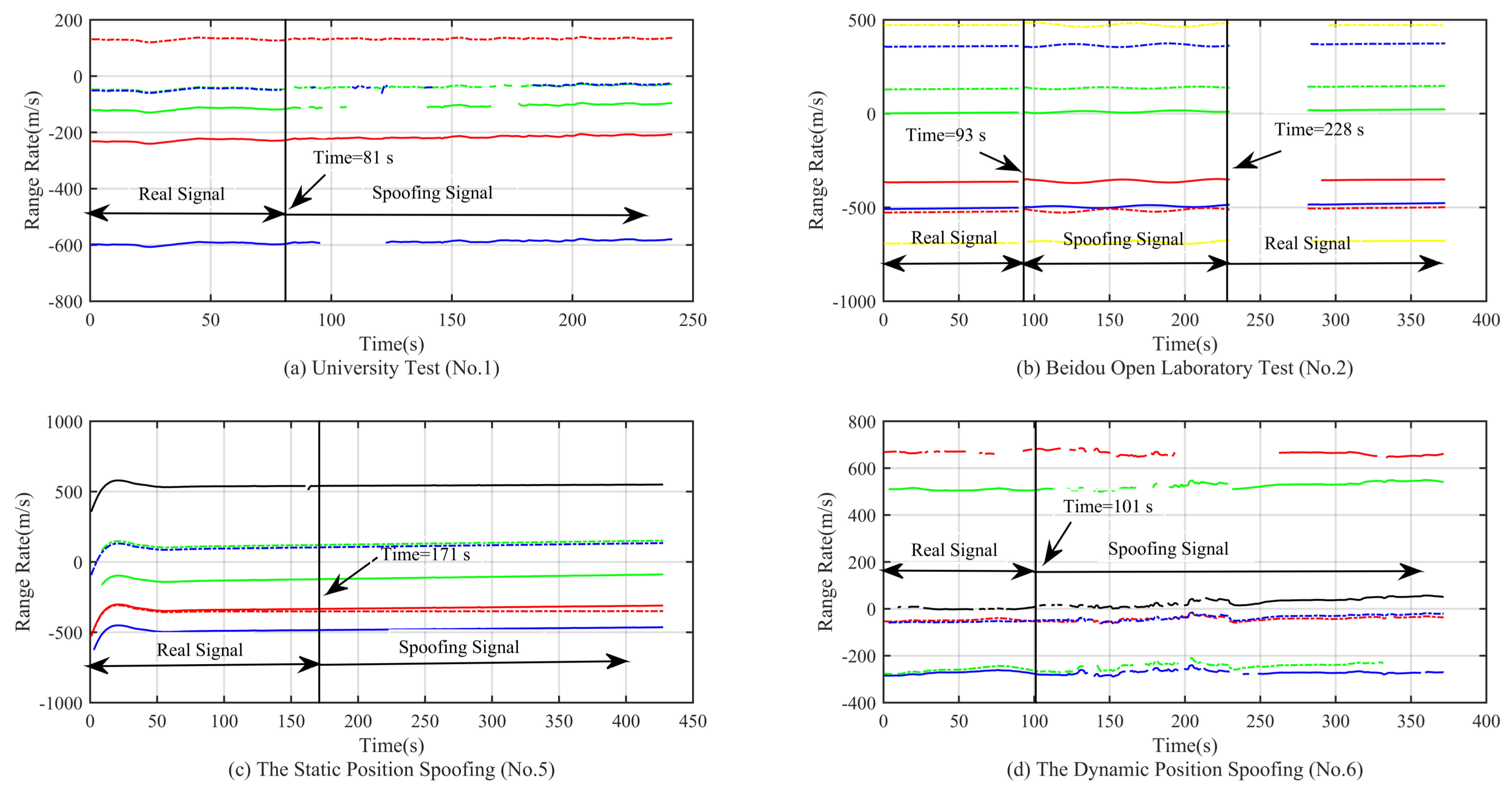
As shown on
Figure 12a,c, there is a slow convergence at the beginning; this is due to the code smoothing process within the receiver. From the simulation results, we can see that when the spoofing signal appears, the clock offset presents an oscillating state, and the amplitude of the oscillation is related to the motion state. For example,
Figure 12a,d shows the cases where the receiver is in a moving state and the clock offset oscillation range is larger than that of
Figure 12b,c. In the Beidou Open Laboratory test, the large oscillation only occurs in the process of signal switching. When the signal is locked in the spoofing signal, the clock offset oscillation is not so obvious, and the spoofing signal has completely taken over the receiver at this time. In addition, it can be seen from the four subfigures in
Figure 12 that the clock offset is not the same magnitude, which limits the application of the method based on the jump detection of the clock offset, as the detection threshold needs to be set in advance. This method cannot be applied to the scenario in which the signal is spoofing from the beginning. From the simulation results in
Figure 13, we can see that the clock drift shows similar characteristics as the clock offset. The range and magnitude of the oscillation will limit the application of this method. Moreover, as can be seen from
Figure 12c and
Figure 13c, there is no obvious change in the clock offset and the clock drift, which poses a challenge for the signal detection based on the method in [
1].
From the simulation result in
Figure 14a,b, we can see that the C/No has a relatively significant change when the spoofing signal is acquired. At this time, we can use the method of C/No jump detection. For the static and dynamic position spoofing scenario, the spoofing signal is switched by a 0.4-dB and a 0.8-dB power advantage, respectively. Therefore, we cannot observe any obvious changes. The method of C/No jump detection is invalid for these two kinds of spoofing scenarios. From the simulation result in
Figure 15, we can see that none of the changes of range rates for these four kinds of spoofing scenarios is obvious. Therefore, the method of range rate jump detection is invalid.
We summarize the detection ability of different methods in
Table 2. From
Table 2, we can see that range rates jump detection is invalid for all scenarios in this paper (in fact, it is only effective for the simplest spoofing attacks). The other three methods (C/No jump detection, clock offset jump detection, clock drift jump detection) would be effective at detecting only some of the spoofing attacks. Our algorithm, proposed in this paper, shows effective detection performance for all the above scenarios.


