Exploiting Concurrent Wake-Up Transmissions Using Beat Frequencies


Abstract
1. Introduction
2. Related Works
2.1. Wireless Interference
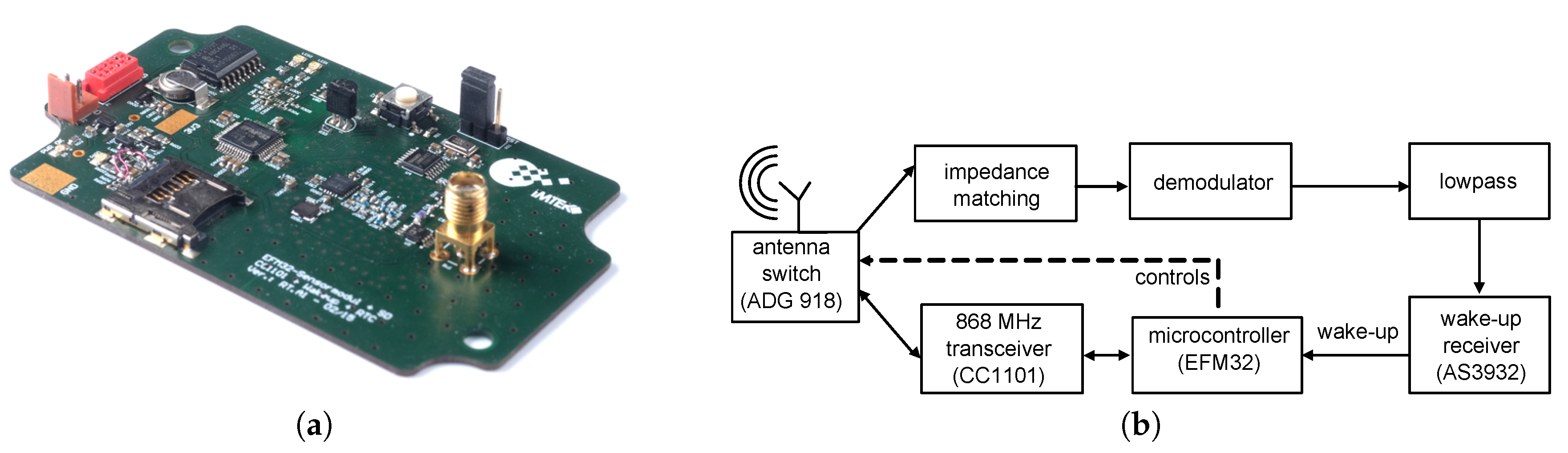
2.2. Wake-Up Receiver
2.3. Zippy
3. Concurrent Wake-Up Message
3.1. Two Concurrent Senders
3.2. More than Two Concurrent Senders
3.3. Performance Simulation
4. Concurrent Wake-Up Protocol Design
4.1. Integration into Existing Routing Protocols
4.2. Concurrent Wake-Up Flooding
5. Experimental Results
5.1. Expected Concurrency of Two Senders
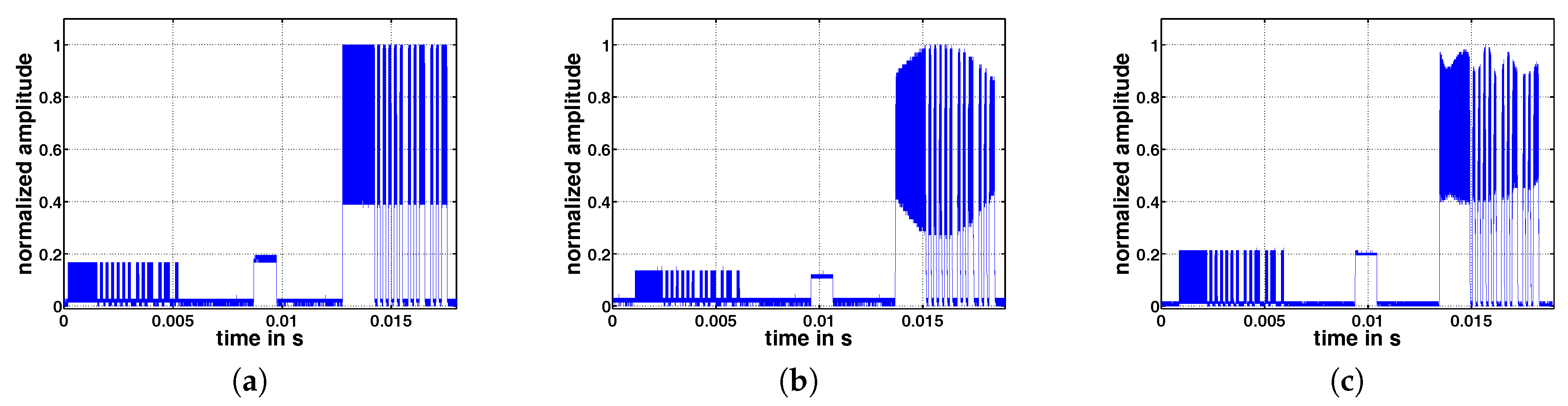
5.2. Concurrent Wake-up Signals
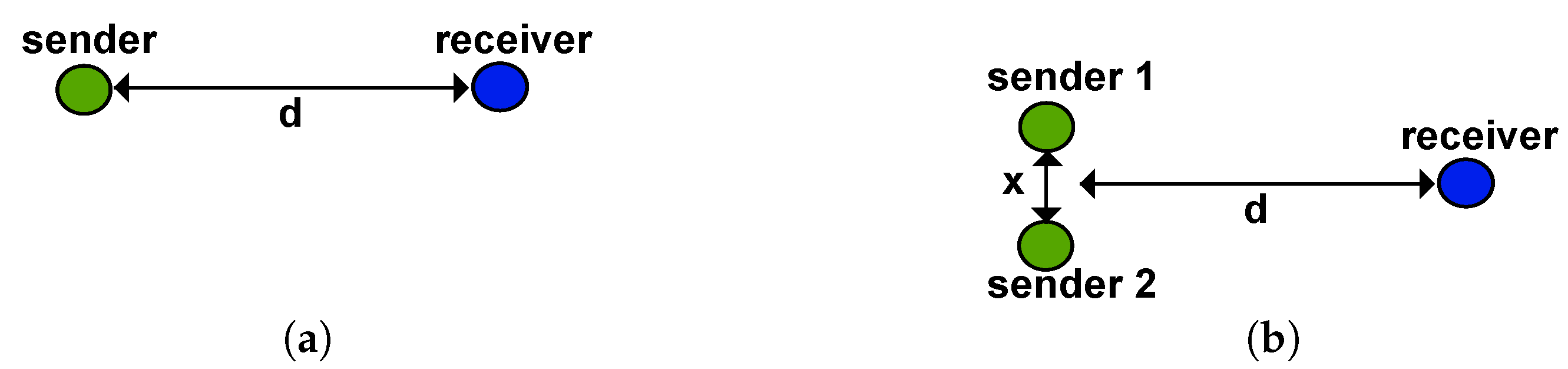
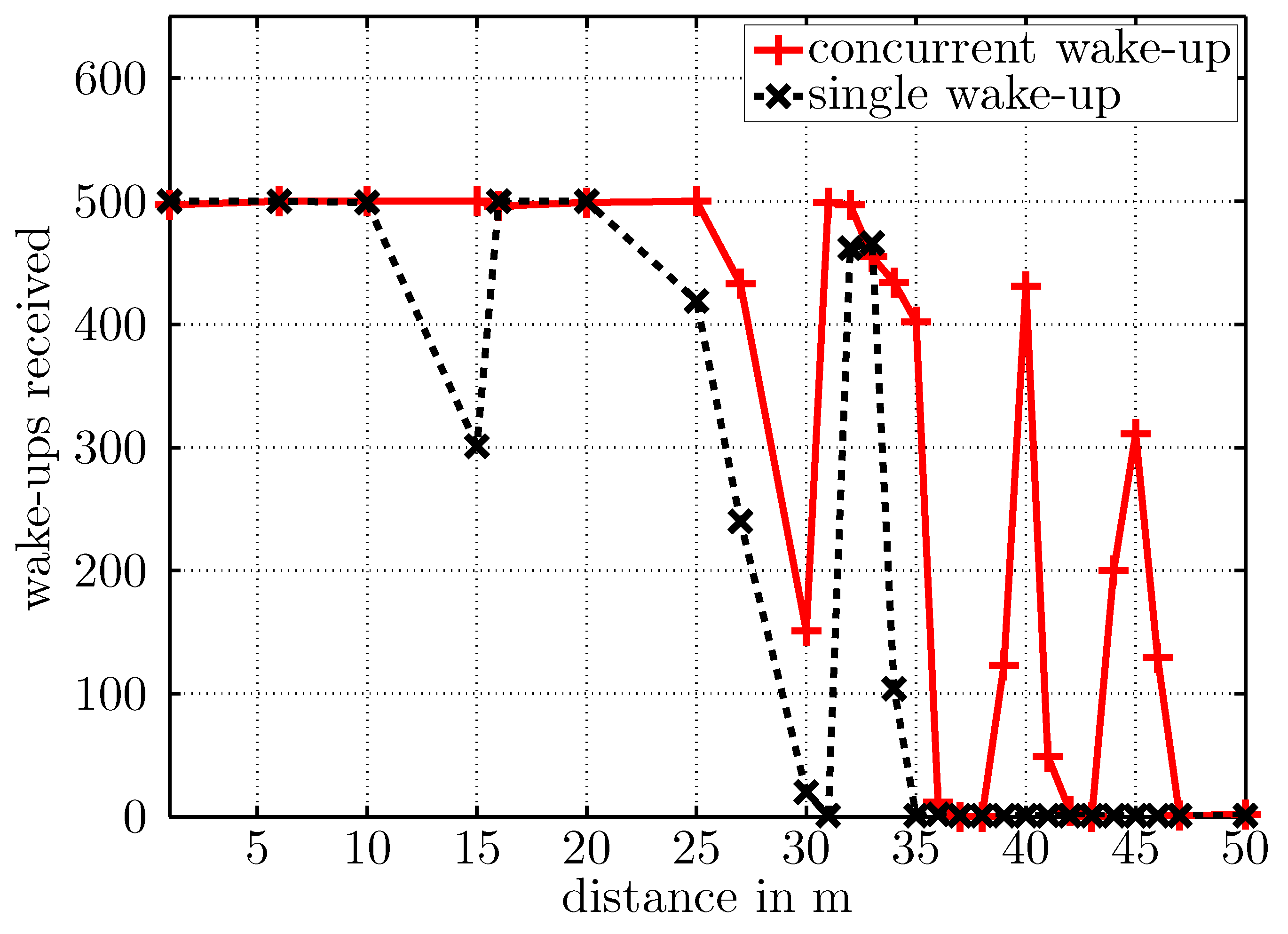
5.3. Free-Space Transmission
5.4. Concurrent Wake-Up Protocol
5.5. Concurrent Wake-Up Flooding
6. Conclusions
Acknowledgments
Author Contributions
Conflicts of Interest
References
- Hoflinger, F.; Gamm, G.U.; Albesa, J.; Reindl, L.M. Smartphone remote control for home automation applications based on acoustic wake-up receivers. In Proceedings of the 2014 IEEE International Instrumentation and Measurement Technology Conference (I2MTC), Montevideo, Uruguay, 12–15 May 2014; pp. 1580–1583. [Google Scholar]
- Bannoura, A.; Höflinger, F.; Gorgies, O.; Gamm, G.U.; Albesa, J.; Reindl, L.M. Acoustic Wake-Up Receivers for Home Automation Control Applications. Electronics 2016, 5, 4. [Google Scholar] [CrossRef]
- Kumberg, T.; Tannhaeuser, R.; Schink, M.; Schneid, S.; Koenig, S.; Schindelhauer, C.; Reindl, L. Wireless wake-up sensor network for structural health monitoring of large-scale highway bridges. In Proceedings of the Second International Conference on Performance-based and Life-cycle Structural Engineering (PLSE 2015), Brisbane, QLD, Australia, 9–11 December 2015; pp. 1393–1401. [Google Scholar]
- Gamm, G.U.; Reindl, L.M. Smart metering using distributed wake-up receivers. In Proceedings of the 2012 IEEE International Instrumentation and Measurement Technology Conference, Graz, Austria, 13–16 May 2012; pp. 2589–2593. [Google Scholar]
- Kumberg, T.; Kokert, J.; Younesi, V.; Koenig, S.; Reindl, L. Wake-up transceivers for structural health monitoring of bridges. In Proceedings of the SPIE Smart Structures and Materials + Nondestructive Evaluation and Health Monitoring, Las Vegas, NV, USA, 15 April 2016; p. 98041S. [Google Scholar]
- Kumberg, T.; Schink, M.; Reindl, L.; Schindelhauer, C. T-ROME: A Simple and Energy Efficient Tree Routing Protocol for Low-Power Wake-up Receivers. Ad Hoc Netw. 2017. [Google Scholar] [CrossRef]
- Ferrari, F.; Zimmerling, M.; Thiele, L.; Saukh, O. Efficient network flooding and time synchronization with glossy. In Proceedings of the 10th ACM/IEEE International Conference on Information Processing in Sensor Networks, Chicago, IL, USA, 12–14 April 2011; pp. 73–84. [Google Scholar]
- Sutton, F.; Buchli, B.; Beutel, J.; Thiele, L. Zippy: On-Demand Network Flooding. In Proceedings of the 13th ACM Conference on Embedded Networked Sensor Systems, Seoul, Korea, 1–4 November 2015; pp. 45–58. [Google Scholar]
- Whitehouse, K.; Woo, A.; Jiang, F.; Polastre, J.; Culler, D. Exploiting the capture effect for collision detection and recovery. In Proceedings of the Second 2005 IEEE Workshop onEmbedded Networked Sensors (EmNetS-II), Sydney, QLD, Australia, 31 May 2005; pp. 45–52. [Google Scholar]
- Son, D.; Krishnamachari, B.; Heidemann, J. Experimental study of concurrent transmission in wireless sensor networks. In Proceedings of the 4th International Conference on Embedded Networked Sensor Systems, Boulder, CO, USA, 31 October–3 November 2006; pp. 237–250. [Google Scholar]
- Dutta, P.; Musaloiu-e, R.; Stoica, I.; Terzis, A. Wireless ACK collisions not considered harmful. In Proceedings of the 7th ACM Workshop on Hot Topics in Networks (HotNets-VII), New York, NY, USA, 6–7 October 2008; pp. 1–6. [Google Scholar]
- Callaway, E.; Gorday, P.; Hester, L.; Gutierrez, J.A.; Naeve, M.; Heile, B.; Bahl, V. Home networking with IEEE 802. 15. 4: A developing standard for low-rate wireless personal area networks. IEEE Commun. Mag. 2002, 40, 70–77. [Google Scholar] [CrossRef]
- Yuan, D.; Hollick, M. Let’s talk together: Understanding concurrent transmission in wireless sensor networks. Proceedings of 2013 IEEE 38th Conference on Local Computer Networks (LCN), Sydney, NSW, Australia, 21–24 October 2013; pp. 219–227. [Google Scholar]
- Wang, Y.; He, Y.; Mao, X.; Liu, Y.; Li, X.Y. Exploiting constructive interference for scalable flooding in wireless networks. IEEE/ACM Trans. Netw. 2013, 21, 1880–1889. [Google Scholar] [CrossRef]
- Wang, Y.; Liu, Y.; He, Y.; Li, X.Y.; Cheng, D. Disco: Improving packet delivery via deliberate synchronized constructive interference. IEEE Trans. Parallel Distrib. Syst. 2015, 26, 713–723. [Google Scholar] [CrossRef]
- Doddavenkatappa, M.; Chan, M.C.; Leong, B. Splash: Fast Data Dissemination with Constructive Interference in Wireless Sensor Networks. In Proceedings of the 10th USENIX Symposium on Networked System Design and Implementation, Lombard, IL, USA, 2–5 April 2013; pp. 269–282. [Google Scholar]
- Yu, S.; Wu, X.; Wu, P.; Wu, D.; Dai, H.; Chen, G. Cirf: Constructive interference-based reliable flooding in asynchronous duty-cycle wireless sensor networks. In Proceedings of the 2014 IEEE Wireless Communications and Networking Conference (WCNC), Istanbul, Turkey, 6–9 April 2014; pp. 2734–2738. [Google Scholar]
- Rao, V.S.; Koppal, M.; Prasad, R.V.; Prabhakar, T.; Sarkar, C.; Niemegeers, I. Murphy loves CI: Unfolding and improving constructive interference in WSNs. In Proceedings of the IEEE INFOCOM 2016-The 35th Annual IEEE International Conference on Computer Communications, San Francisco, CA, USA, 10–14 April 2016; pp. 1–9. [Google Scholar]
- Escobar, A.; Cruz, F.J.; Garcia-Jimenez, J.; Klaue, J.; Corona, A. RedFixHop with channel hopping: Reliable ultra-low-latency network flooding. In Proceedings of the 2016 Conference on Design of Circuits and Integrated Systems (DCIS), Granada, Spain, 23–25 November 2016; pp. 1–4. [Google Scholar]
- Gamm, G.U.; Kostic, M.; Sippel, M.; Reindl, L.M. Low–power sensor node with addressable wake–up on–demand capability. Int. J. Sens. Netw. 2012, 11, 48–56. [Google Scholar] [CrossRef]
- Kumberg, T.; Tannhaeuser, R.; Gamm, G.U.; Reindl, L.M. Energy improved wake-up strategy for wireless sensor networks. In Proceedings of the Sensors and Measuring Systems 2014, ITG/GMA Symposium. Nuremberg, Germany, 3–4 June 2014; pp. 1–6. [Google Scholar]
- Magno, M.; Benini, L. An ultra low power high sensitivity wake-up radio receiver with addressing capability. In Proceedings of the 2014 IEEE 10th International Conference on Wireless and Mobile Computing, Networking and Communications (WiMob), Larnaca, Cyprus, 8–10 October 2014; pp. 92–99. [Google Scholar]
- Kumberg, T.; Tannhaeuser, R.; Reindl, L. Using antenna diversity to improve wake-up range and probability. In Proceedings of the PIERS 2015, Prague, Czech Republic, 6–9 July 2015. [Google Scholar]
- Blanckenstein, J.; Klaue, J.; Karl, H. A Survey of Low-Power Transceivers and Their Applications. IEEE Circuits Syst. Mag. 2015, 15, 6–17. [Google Scholar] [CrossRef]
- Oller, J.; Demirkol, I.; Casademont, J.; Paradells, J.; Gamm, G. U.; Reindl, L. Has time come to switch from duty-cycled MAC protocols to wake-up radio for wireless sensor networks? IEEE/ACM Trans. Netw. 2016, 24, 674–687. [Google Scholar] [CrossRef]
- Rappaport, T.S. Wireless Communications: Principles and Practice; Prentice Hall PTR: Upper Saddle River, NJ, USA, 1996; Volume 2. [Google Scholar]
- Kvaksrud, T.I. Range Measurements in an Open Field Environment; Design Note DN018; Texas Instruments: Dallas, TX, USA, 2008. [Google Scholar]
- Basagni, S.; Petrioli, C.; Spenza, D. CTP-WUR: The collection tree protocol in wake-up radio WSNs for critical applications. In Proceedings of the 2016 International Conference on Computing, Networking and Communications (ICNC), Kauai, HI, USA, 15–18 February 2016; pp. 1–6. [Google Scholar]
- Spenza, D.; Magno, M.; Basagni, S.; Benini, L.; Paoli, M.; Petrioli, C. Beyond duty cycling: Wake-up radio with selective awakenings for long-lived wireless sensing systems. In Proceedings of the 2015 IEEE Conference on Computer Communications (INFOCOM), Kowloon, Hong Kong, China, 26 April–1 May 2015; pp. 522–530. [Google Scholar]
- Chen, L.; Warner, J.; Heinzelman, W.; Demirkol, I. MH-REACH-Mote: Supporting multi-hop passive radio wake-up for wireless sensor networks. In Proceedings of the 2015 IEEE International Conference on Communications (ICC), London, UK, 8–12 June 2015; pp. 6512–6518. [Google Scholar]
- Ait Aoudia, F.; Gautier, M.; Berder, O. OPWUM: Opportunistic MAC protocol leveraging wake-up receivers in WSNs. J. Sens. 2016. [Google Scholar] [CrossRef]
- Kumberg, T.; Reindl, L.; Moharrami, M.; Schindelhauer, C. Improving the Performance of the Cross-Layer Wake-Up Routing Protocol T-ROME. In Proceedings of the 13th International Wireless Communications and Mobile Computing Conference (IWCMC), Valencia, Spain, 26–30 June 2017; pp. 780–785. [Google Scholar]


| Node | Frequency in MHz | Type | Number of Wake-Ups Sent | Number of Wake-Ups Received |
|---|---|---|---|---|
| 1 | 868 | initiator | 500 | – |
| 2 | 868.125 | sender | 500 | 500 |
| 3 | 865 | sender | 500 | 500 |
| 4 | 865.125 | sender | 499 | 499 |
| 5 | – | receiver | – | 1000 |
| 6 | 866.125 | sender | 500 | 500 |
| 7 | 866 | sender | 483 | 483 |
| 8 | – | receiver | – | 500 |
| 9 | – | receiver | – | 499 |
| 10 | – | receiver | – | 495 |
| 11 | – | receiver | – | 500 |
© 2017 by the authors. Licensee MDPI, Basel, Switzerland. This article is an open access article distributed under the terms and conditions of the Creative Commons Attribution (CC BY) license (http://creativecommons.org/licenses/by/4.0/).
Share and Cite
Kumberg, T.; Schindelhauer, C.; Reindl, L. Exploiting Concurrent Wake-Up Transmissions Using Beat Frequencies. Sensors 2017, 17, 1717. https://doi.org/10.3390/s17081717
Kumberg T, Schindelhauer C, Reindl L. Exploiting Concurrent Wake-Up Transmissions Using Beat Frequencies. Sensors. 2017; 17(8):1717. https://doi.org/10.3390/s17081717
Chicago/Turabian StyleKumberg, Timo, Christian Schindelhauer, and Leonhard Reindl. 2017. "Exploiting Concurrent Wake-Up Transmissions Using Beat Frequencies" Sensors 17, no. 8: 1717. https://doi.org/10.3390/s17081717
APA StyleKumberg, T., Schindelhauer, C., & Reindl, L. (2017). Exploiting Concurrent Wake-Up Transmissions Using Beat Frequencies. Sensors, 17(8), 1717. https://doi.org/10.3390/s17081717