Paper as Active Layer in Inkjet-Printed Capacitive Humidity Sensors

Abstract
:1. Introduction
2. Materials and Methods
2.1. Materials
2.2. Surface Characterization Methods
2.3. Inkjet-Printing and Sintering Conditions
2.4. Capacitive Humidity Measurements
3. Results and Discussion
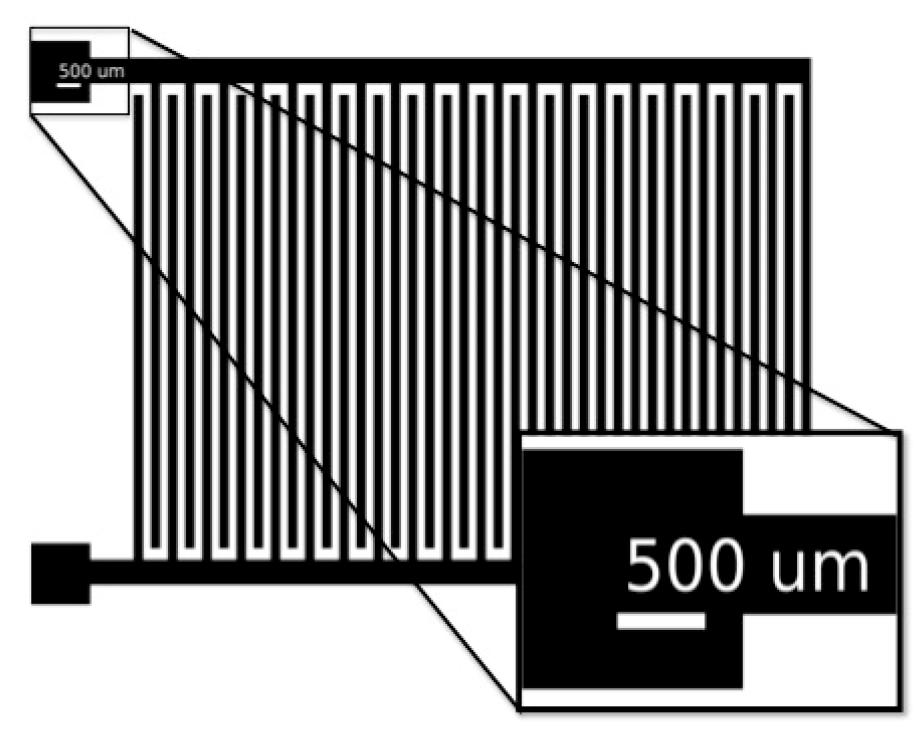
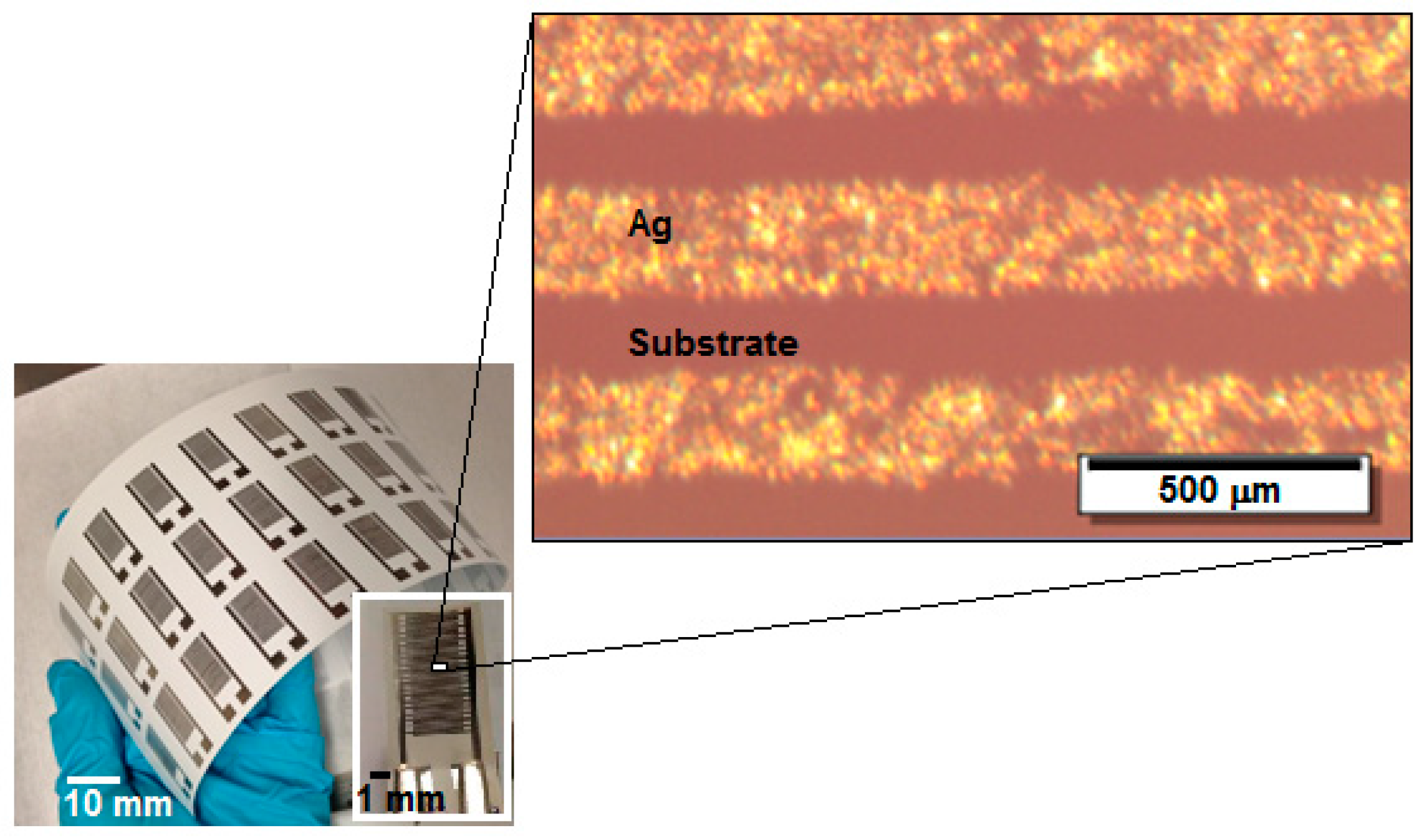
3.1. Inkjet-Printing of the Sensor Structure on Paper
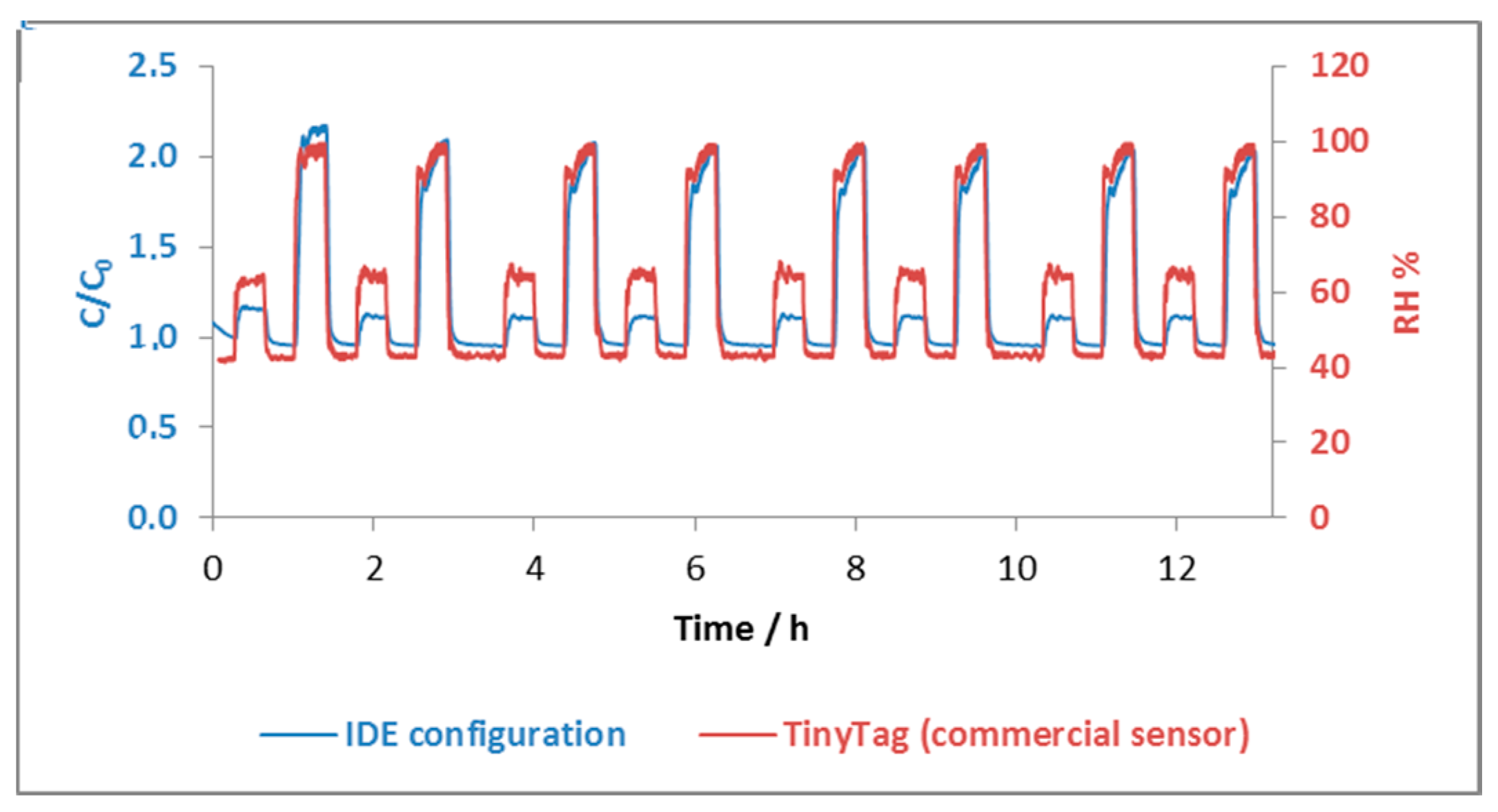
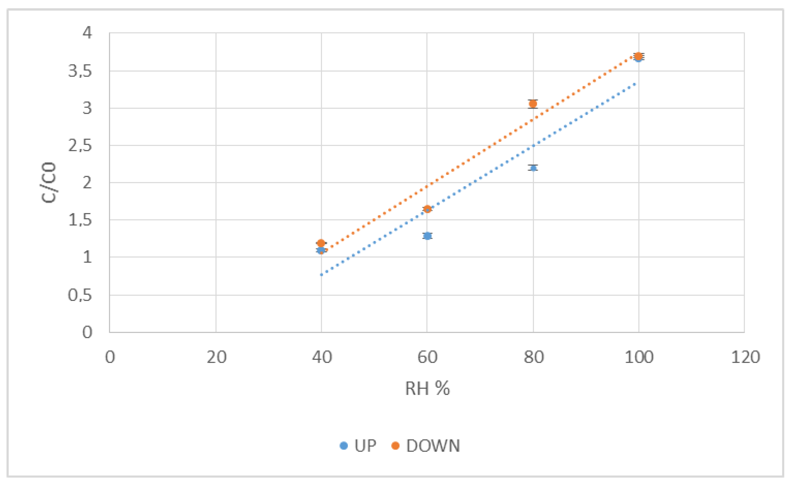
3.2. Capacitive Humidity Measurements
4. Conclusions
Acknowledgments
Author Contributions
Conflicts of Interest
References
- Tobjörk, D.; Österbacka, R. Review: Paper Electronics. Adv. Mater. 2011, 23, 1935–1961. [Google Scholar] [CrossRef] [PubMed]
- Molina-Lopez, F.; Briand, D.; de Rooij, N.F. All additive inkjet-printed humidity sensors on plastic substrate. Sens. Actuators B Chem. 2012, 166–167, 212–222. [Google Scholar] [CrossRef]
- Gomes, T.C.; Constantino, C.J.L.; Lopes, E.M.; Job, A.E.; Alves, N. Thermal inkjet printing of polyaniline on paper. Thin Solid Films 2012, 520, 7200–7204. [Google Scholar] [CrossRef]
- Weremczuk, J.; Tarapata, G.; Jachowicz, R. Humidity Sensor Printed on Textile with Use of Ink-Jet Technology. Procedia Eng. 2012, 47, 1366–1369. [Google Scholar] [CrossRef]
- Merilampi, S.; Laine-Ma, T.; Ruuskanen, P. The characterization of electrically conductive silver ink patterns on flexible substrates. Microelectron. Reliab. 2009, 49, 782–790. [Google Scholar] [CrossRef]
- Perelaer, J.; Laat, A.W.M.; Hendriks, C.E.; Schubert, U.S. Inkjet-printed silver tracks: Low temperature curing and thermal stability investigation. J. Mater. Chem. 2008, 18, 3209–3215. [Google Scholar] [CrossRef]
- Chiolerio, A.; Cotto, M.; Pandolfi, P.; Martino, P.; Camarchia, V.; Pirola, M.; Ghione, G. Ag nanoparticle-based inkjet printed planar transmission lines for RF and microwave applications: Considerations on ink composition, nanoparticle size distribution and sintering time. Microelectron. Eng. 2012, 97, 8–15. [Google Scholar] [CrossRef]
- Tobjörk, D.; Aarnio, H.; Pulkkinen, P.; Bollström, R.; Määttänen, A.; Ihalainen, P.; Mäkelä, T.; Peltonen, J.; Toivakka, M.; Tenhu, H.; et al. IR-sintering of ink-jet printed metal-nanoparticles on paper. Thin Solid Films 2012, 520, 2949–2955. [Google Scholar] [CrossRef]
- Lewis, L.N.; Spivack, J.L.; Gasaway, S.; Williams, E.D.; Gui, J.Y.; Manivannan, V.; Siclovan, O.P. A novel UV-mediated low temperature sintering of TiO2 for dye-sensitized solar cells, Solar Energy. Mater. Sol. Cells 2006, 90, 1041–1051. [Google Scholar] [CrossRef]
- Yung, K.C.; Gu, X.; Lee, C.P.; Choy, H.S. Ink-jet printing and camera flash sintering of silver tracks on different substrates. Mater. Process. Technol. 2010, 210, 2268–2272. [Google Scholar] [CrossRef]
- Chung, J.; Ko, S.; Bieri, N.; Grigoropoulos, C.; Poulikakos, D. Conductor microstructures by laser curing of printed gold nanoparticle ink. Appl. Phys. Lett. 2004, 84, 801. [Google Scholar] [CrossRef]
- Reinhold, I.; Hendriks, C.E.; Eckardt, R.; Kranenburg, J.M.; Perelaer, J.; Baumann, R.R.; Schubert, U.S. Argon plasma sintering of inkjet printed silver tracks on polymer substrates. J. Mater. Chem. 2009, 19, 3384–3388. [Google Scholar] [CrossRef]
- Perelaer, J.; Gans, B.; Schubert, U. Ink-jet printing and microwave sintering of conductive silver tracks. Adv. Mater. 2006, 18, 2101–2104. [Google Scholar] [CrossRef]
- Wu, J.; Hsu, S.; Tsai, M.; Hwang, W. Conductive silver patterns via ethylene glycol vapor reduction of ink-jet printed silver nitrate tracks on a polyimide substrate. Thin Solid Films 2009, 517, 5913–5917. [Google Scholar] [CrossRef]
- Allen, M.L.; Aronniemi, M.; Mattila, T.; Alastalo, A.; Ojanpera, K.; Suhonen, M.; Seppä, H. Electrical sintering of nanoparticle structures. Nanotechnology 2008, 19, 175–201. [Google Scholar] [CrossRef] [PubMed]
- Li, Y.; Yang, M.J. A novel highly reversible humidity sensor based on poly(2-propyn-2-furoate). Sens. Actuators B Chem. 2002, 86, 155–159. [Google Scholar] [CrossRef]
- Igreja, R.; Dias, C.J. Analytical evaluation of the interdigital electrodes capacitance for a multi-layered structure. Sens. Actuators A Phys. 2004, 112, 291–301. [Google Scholar] [CrossRef]
- Mraović, M.; Muck, T.; Pivar, M.; Trontelj, J.; Pleteršek, A. Humidity Sensors Printed on Recycled Paper and Cardboard. Sensors 2014, 14, 13628–13643. [Google Scholar] [CrossRef] [PubMed]
- Han, J.W.; Kim, B.; Li, J.; Meyyappan, M. Carbon Nanotube Based Humidity Sensor on Cellulose Paper. J. Phys. Chem. C 2012, 116, 22094–22097. [Google Scholar] [CrossRef]
- Rivadeneyra, A.; Fernández-Salmerón, J.; Agudo-Acemel, M.; López-Villanueva, J.A.; Capitan-Vallvey, L.F.; Palma, A.J. Printed electrodes structures as capacitive humidity sensors: A comparison. Sens. Actuators A Phys. 2016, 244, 56–65. [Google Scholar] [CrossRef]
- Harrey, P.M.; Ramsey, B.J.; Evans, P.S.A.; Harrison, D.J. Capacitive-type humidity sensors fabricated using the offset lithographic printing process. Sens. Actuators B Chem. 2002, 87, 226–232. [Google Scholar] [CrossRef]
- Rivadeneyra, A.; Fernández-Salmerón, J.; Agudo-Acemel, M.; López-Villanueva, J.A.; Palma, A.J.; Capitan-Vallvey, L.F. A printed capacitive–resistive double sensor for toluene and moisture sensing. Sens. Actuators B Chem. 2015, 210, 542–549. [Google Scholar] [CrossRef]
- Unander, T.; Nilsson, H.E. Characterization of Printed Moisture Sensors in Packaging Surveillance Applications. IEEE Sens. J. 2009, 9, 922–928. [Google Scholar] [CrossRef]
- Cho, N.B.; Lim, T.H.; Jeon, Y.M.; Gong, M.S. Humidity sensors fabricated with photo-curable electrolyte inks using an ink-jet printing technique and their properties. Sens. Actuators B Chem. 2008, 130, 594–598. [Google Scholar] [CrossRef]
- Feng, Y.; Xie, L.; Chen, Q.; Zheng, L.R. Low-Cost Printed Chipless RFID Humidity Sensor Tag for Intelligent Packaging. IEEE Sens. J. 2015, 15, 3201. [Google Scholar] [CrossRef]
- Gomes, T.C.; Oliveira, R.F.; Lopes, É.M.; Klem, M.S.; Agostini, D.L.S.; Constantino, C.J.L.; Alves, N. Effects of humidity on the electrical properties of thermal inkjet-printed films of copper tetrasulfonated phthalocyanine (CuTsPc) onto paper substrates. J. Mater. Sci. 2015, 50, 2122–2129. [Google Scholar] [CrossRef]
- Courbat, J.; Kim, Y.B.; Briand, D.; de Rooij, N.F. Inkjet printing on paper for the realization of humidity and temperature sensors. In Proceedings of the Solid-State Sensors, Actuators and Microsystems Conference (TRANSDUCERS), Beijing, China, 5–9 June 2011. [Google Scholar] [CrossRef]
- Soltman, D.; Subramanian, V. Inkjet-Printed Line Morphologies and Temperature Control of the Coffee Ring effect. Langmuir 2008, 24, 2224–2231. [Google Scholar] [CrossRef] [PubMed]
- Gaspar, C.; Passoja, S.; Olkkonen, J.; Smolander, M. IR-sintering efficiency on inkjet-printed conductive structures on paper. Microelectron. Eng. 2016, 149, 135–140. [Google Scholar] [CrossRef]
- Igreja, R.; Dias, C. Dielectric response of interdigital chemocapacitors: The role of the sensitive layer thickness. Sens. Actuators B Chem. 2006, 115, 69–78. [Google Scholar] [CrossRef]
- Gu, L.; Huang, Q.A.; Qin, M. A novel capacitive-type humidity sensor using CMOS fabrication technology. Sens. Actuators B Chem. 2004, 99, 491–498. [Google Scholar] [CrossRef]
- Chen, W.P.; Zhao, Z.G.; Liu, X.W.; Zhang, Z.X.; Suo, C.G. A Capacitive Humidity Sensor Based on Multi-Wall Carbon Nanotubes (MWCNTs). Sensors 2009, 9, 7431–7444. [Google Scholar] [CrossRef] [PubMed]
- Lee, H.; Lee, S.; Jung, S.; Lee, J. Nano-grass polyimide-based humidity sensors. Sens. Actuators B Chem. 2011, 154, 2–8. [Google Scholar] [CrossRef]
- Rivadeneyra, A.; Fernández-Salmerón, J.; Agudo, M.; López-Villanueva, J.A.; Capitan-Vallvey, L.F.; Palma, A.J. Design and characterization of a low thermal drift capacitive humidity sensor by inkjet-printing. Sens. Actuators B Chem. 2014, 195, 123–131. [Google Scholar] [CrossRef]
- Dang, M.C.; Nguyen, D.S.; Dang, T.M.D.; Tedjini, S.; Fribourg-Blanc, E. Design and testing of RFID sensor tag fabricated using inkjet-printing and electrodeposition. Adv. Nat. Sci. Nanosci. Nanotechnol. 2014, 5, 025012. [Google Scholar] [CrossRef]
- Barras, R.; Cunha, I.; Gaspar, D.; Fortunato, E.; Martins, R.; Pereira, L. Printable cellulose-based electroconductive composites for sensing elements in paper electronics. Flex. Print. Electron. 2017, 2, 014006. [Google Scholar] [CrossRef]
- Wang, X.; Larsson, O.; Platt, D.; Nordlinder, S.; Engquist, I.; Berggren, M.; Crispin, X. An all-printed wireless humidity sensor label. Sens. Actuators B Chem. 2012, 166–167, 556–561. [Google Scholar] [CrossRef]
- Sandberg, H.G.O.; Gaspar, C.; Hakola, L.; Rentrop, C. Integrated printed hybrid electronics on paper. In Proceedings of the 5th Electronics System-Integration Technology Conference, ESTC, Helsinki, Finland, 16–18 September 2014. [Google Scholar] [CrossRef]
- Hakola, L.; Gaspar, C.; Ilmonen, A.; Lehtinen, K.; Smolander, M. Printed intelligence for consumer products. In Proceedings of the 5th Electronics System-Integration Technology Conference, ESTC, Helsinki, Finland, 16–18 September 2014. [Google Scholar] [CrossRef]
- Robin, M.; Kuai, W.; Amela-Cortes, M.; Cordier, S.; Molard, Y.; Mohammed-Brahim, T.; Jacques, E.; Harnois, M. Epoxy Based Ink as Versatile Material for Inkjet-Printed Devices. ACS Appl. Mater. Interfaces 2015, 7, 21975–21984. [Google Scholar] [CrossRef] [PubMed]
- Ye, T.; Jun, L.; Kun, L.; Hu, W.; Ping, C.; Ya-Hui, D.; Zheng, C.; Yun-Fei, L.; Hao-Ran, W.; Yu, D. Inkjet-printed Ag grid combined with Ag nanowires to form a transparent hybrid electrode for organic electronics. Org. Electron. 2017, 179–185. [Google Scholar] [CrossRef]


| Parameter | Si-Based Commercial Sensor | Paper-Based Inkjet-Printed Sensor | Polymer-Based Inkjet-Printed Sensor [34] | Inkjet-Printed Humidity Sensor on Paper [27] | CNTs/Paper-Based Resistive Sensor [19] | CuTsPc/Paper-Based Resistive Sensor [26] |
|---|---|---|---|---|---|---|
| Nominal capacitance (pF) @ room temperature | 300 (55 RH %) | 10 (55 RH %) | 2 (40 RH %) | 23 | n.d. | n.d. |
| Sensitivity (pF /RH %) | 0.6 pF | ~ 2 pF | 4.5 fF | n.d. | 6% (linear regime) | n.d. |
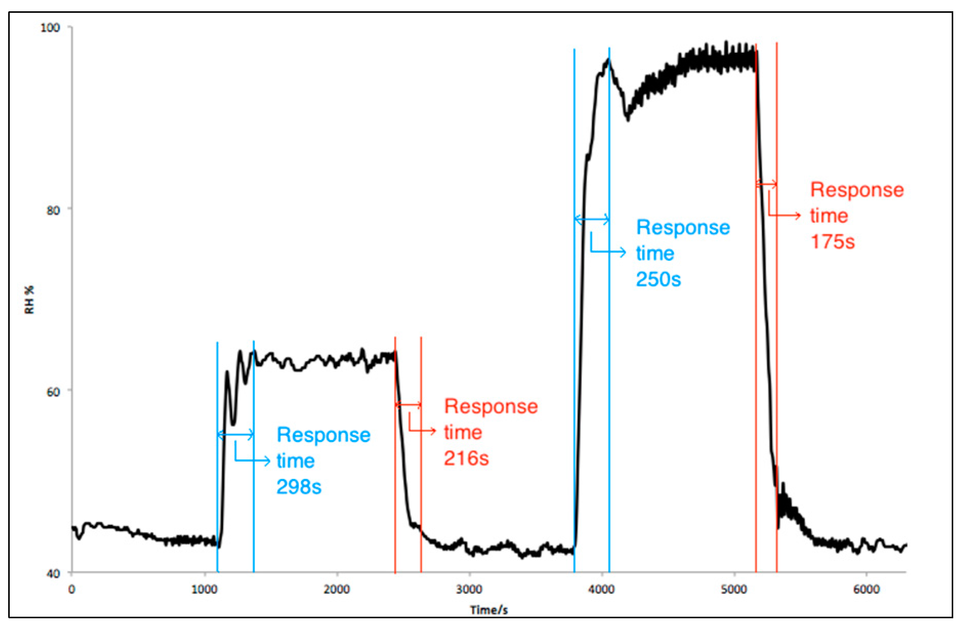
| Response time | Fast (seconds) | Slow (4–5 min) | 6 min | Very long | 6 s | 8 min |
© 2017 by the authors. Licensee MDPI, Basel, Switzerland. This article is an open access article distributed under the terms and conditions of the Creative Commons Attribution (CC BY) license (http://creativecommons.org/licenses/by/4.0/).
Share and Cite
Gaspar, C.; Olkkonen, J.; Passoja, S.; Smolander, M. Paper as Active Layer in Inkjet-Printed Capacitive Humidity Sensors. Sensors 2017, 17, 1464. https://doi.org/10.3390/s17071464
Gaspar C, Olkkonen J, Passoja S, Smolander M. Paper as Active Layer in Inkjet-Printed Capacitive Humidity Sensors. Sensors. 2017; 17(7):1464. https://doi.org/10.3390/s17071464
Chicago/Turabian StyleGaspar, Cristina, Juuso Olkkonen, Soile Passoja, and Maria Smolander. 2017. "Paper as Active Layer in Inkjet-Printed Capacitive Humidity Sensors" Sensors 17, no. 7: 1464. https://doi.org/10.3390/s17071464
APA StyleGaspar, C., Olkkonen, J., Passoja, S., & Smolander, M. (2017). Paper as Active Layer in Inkjet-Printed Capacitive Humidity Sensors. Sensors, 17(7), 1464. https://doi.org/10.3390/s17071464