A New Method for Land Vehicle Gravimetry Using SINS/VEL

Abstract
:1. Introduction
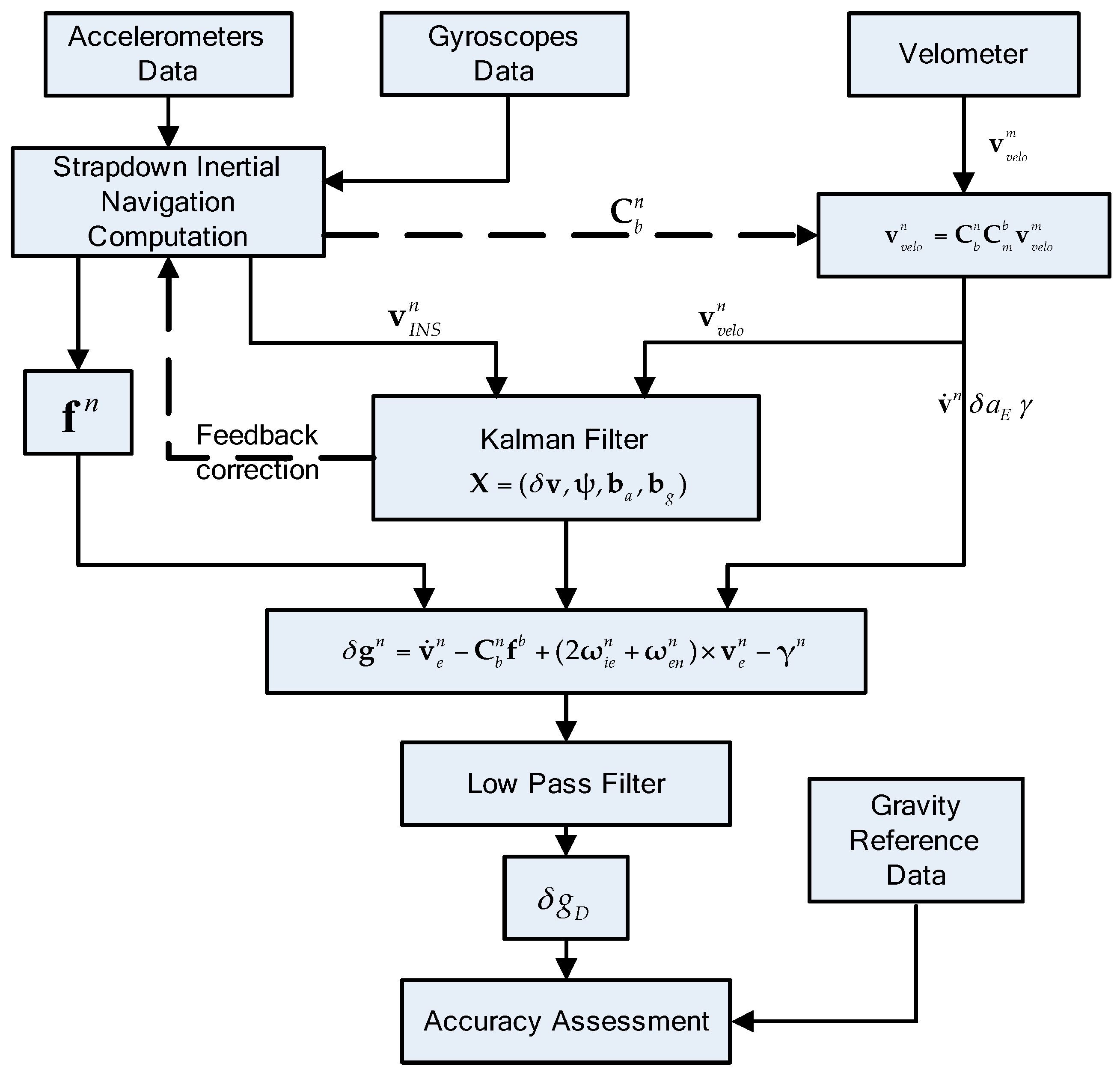
2. Principle
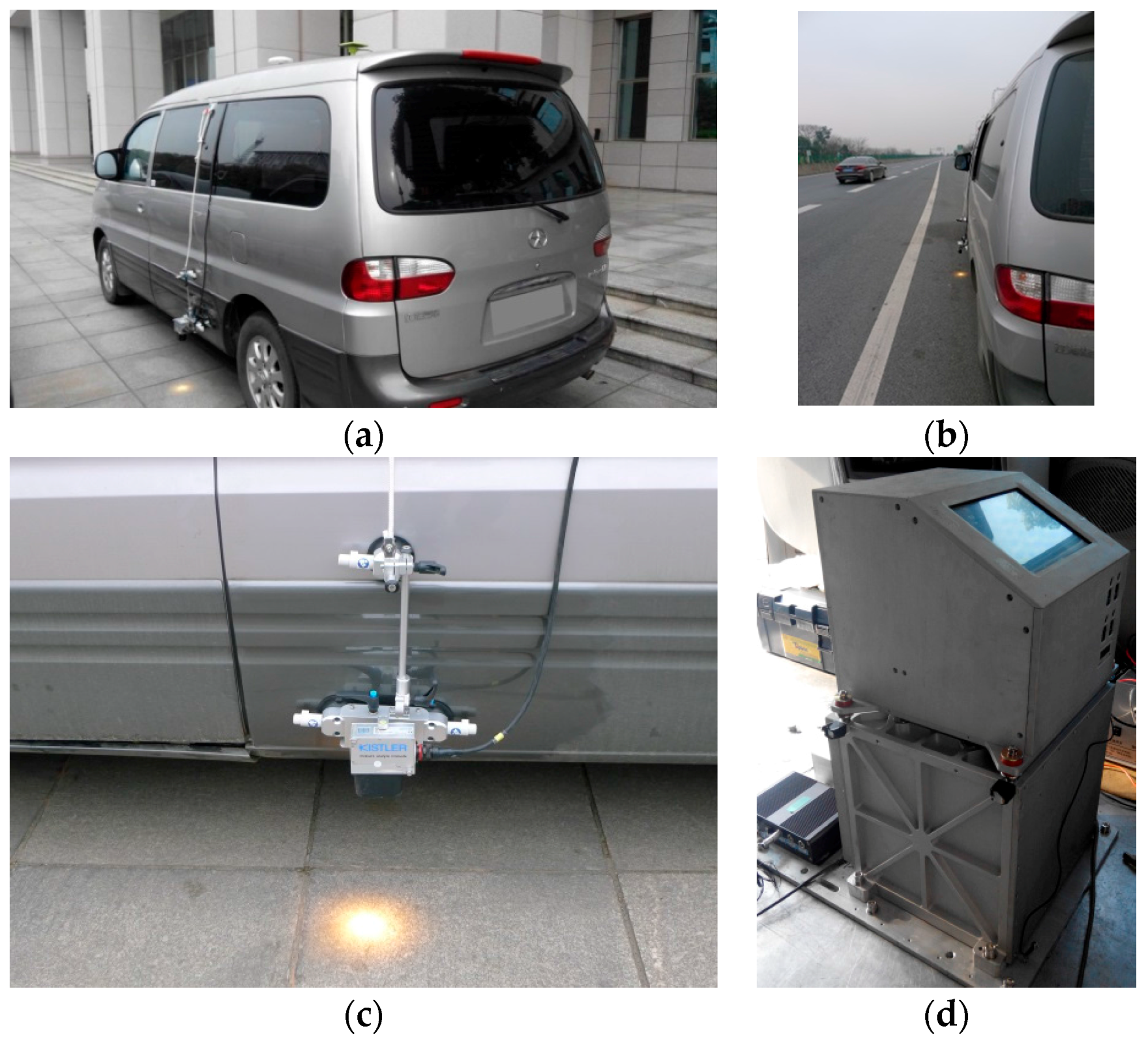
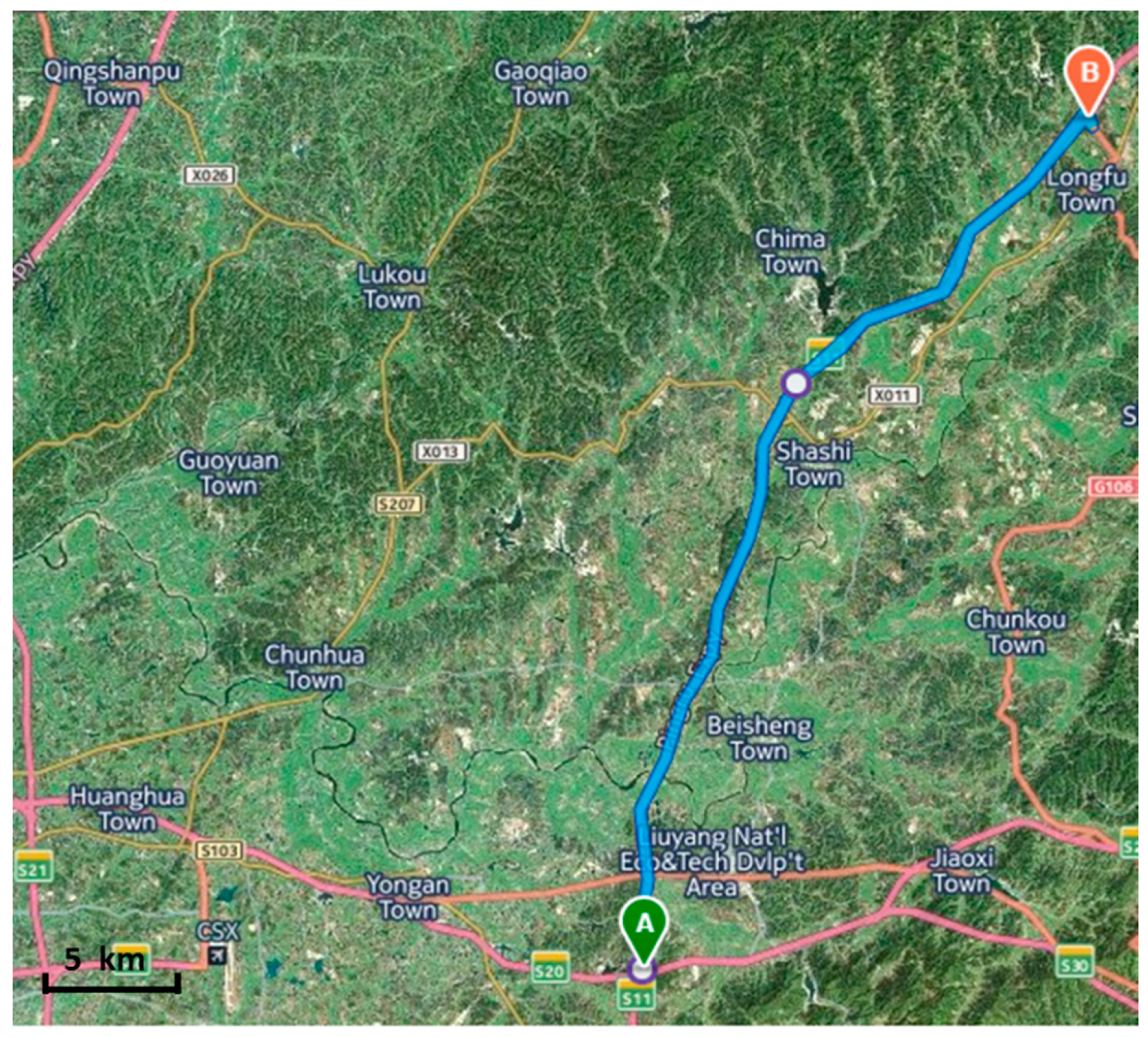
3. Experiments
4. Results and Discussion
4.1. Data Processing
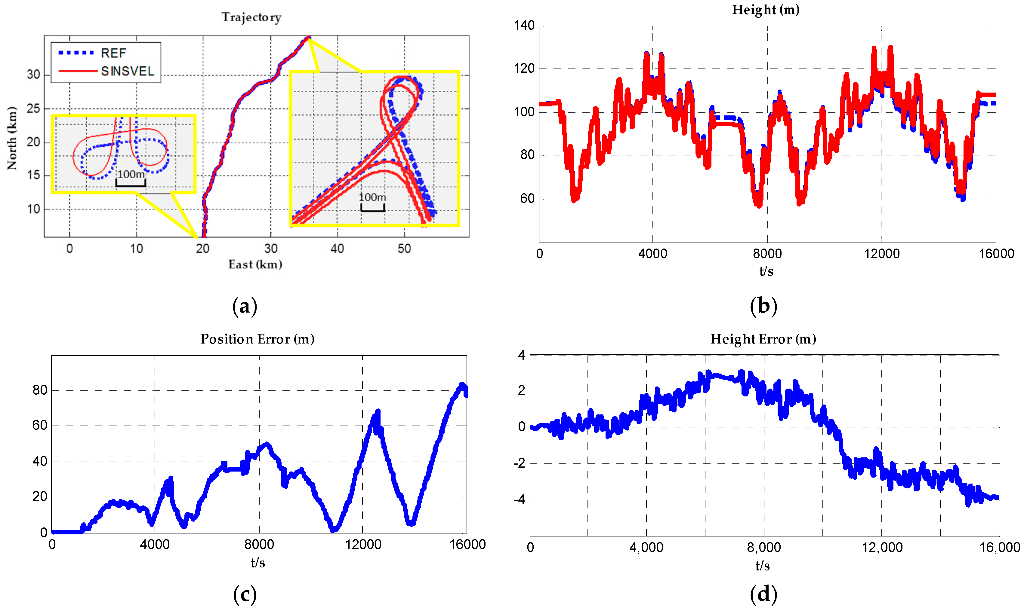
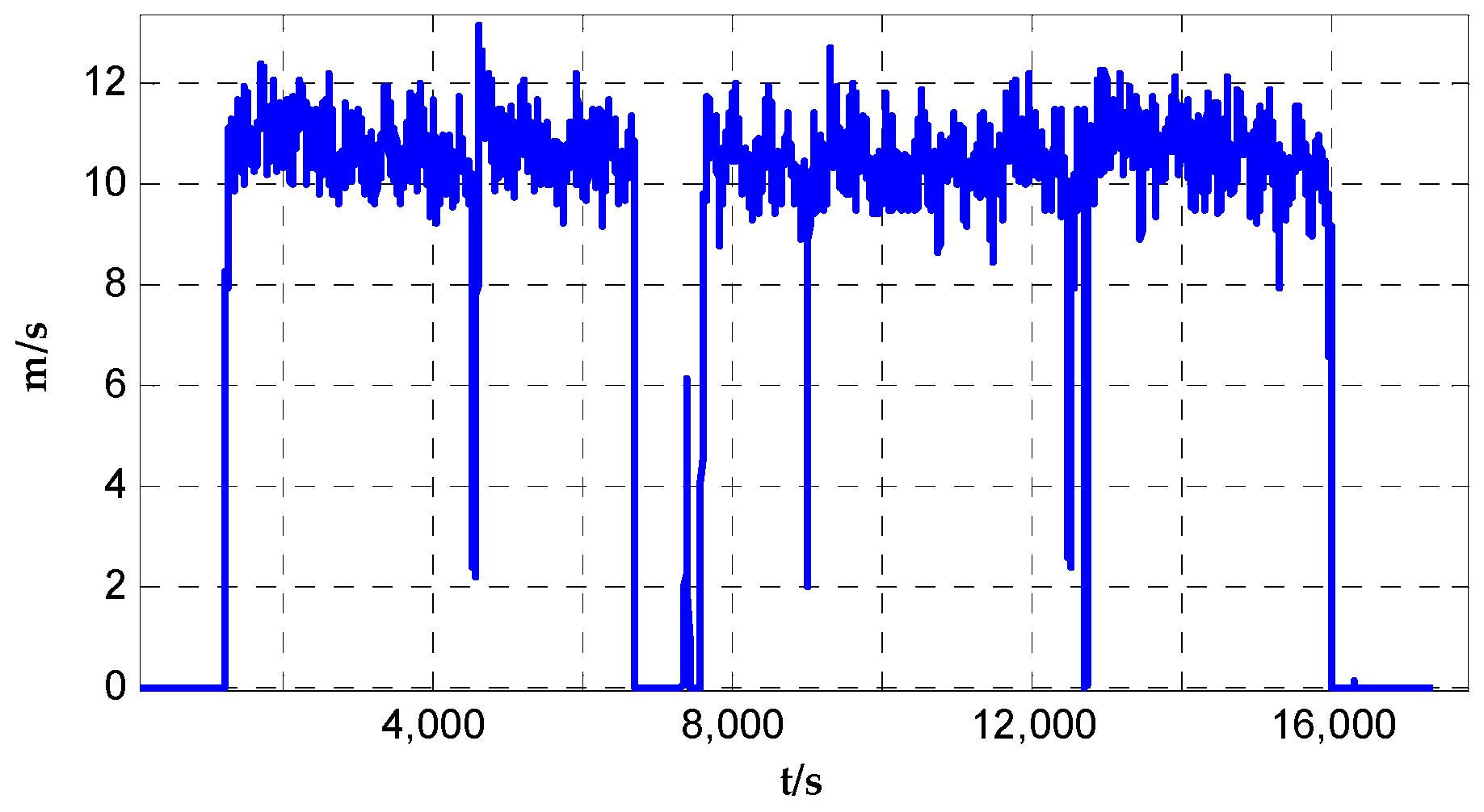
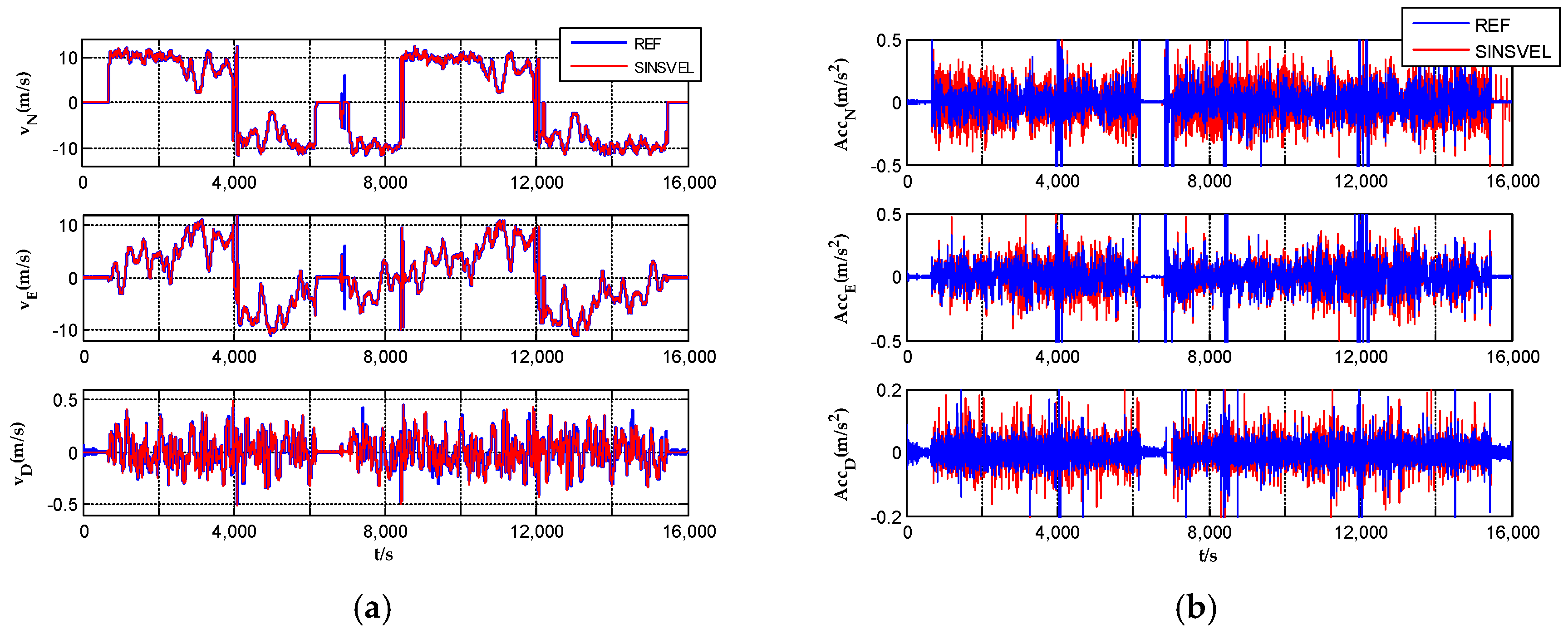
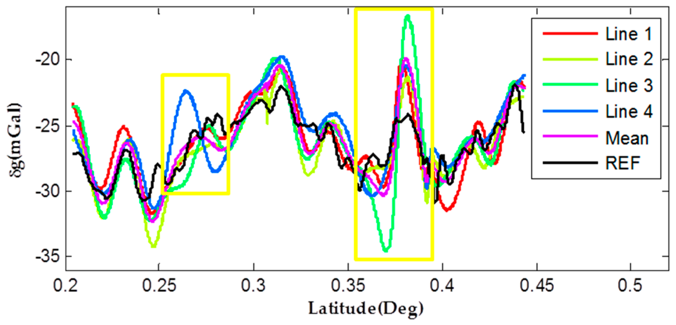
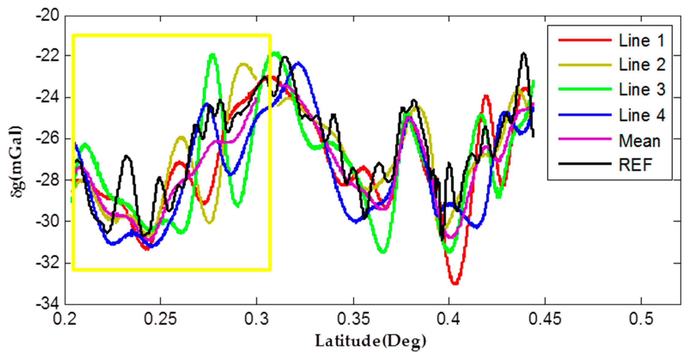
4.2. Test Results and Analysis
5. Conclusions
Acknowledgments
Author Contributions
Conflicts of Interest
References
- Kwon, J.H. Airborne Vector Gravimetry Using GPS/INS. Ph.D. Thesis, Department of Civil and Environmental Engineering and Geodetic Science, The Ohio State University, Columbus, OH, USA, 2000. [Google Scholar]
- Schwarz, K.P.; Wei, M. Some unsolved problems in airborne gravimetry. In Gravity and Geoid; Sünkel, H., Marson, I., Eds.; Springer: Berlin, Germany, 1995; pp. 131–150. [Google Scholar]
- Zhang, K. Research on the Methods of Airborne Gravimetry Based on SINS/DGPS. Ph.D. Thesis, National University of Defense Technology, Changsha, China, 2007. [Google Scholar]
- Jekeli, C. Airborne vector gravimetry using precise, position-aided inertial measurement units. Bull. Géod. 1994, 69, 1–11. [Google Scholar] [CrossRef]
- Bruton, A.M. Improving the Accuracy and Resolution of SINS/DGPS Airborne Gravimetry. Ph.D. Thesis, University of Calgar, Calgary, AB, Canada, 2000. [Google Scholar]
- Forsberg, R.; Olesen, A.; Keller, K.; Møller, M.; Gidskehaug, A.; Solheim, D. Airborne gravity and geoid surveys in the arctic and baltic seas. Proceedings of International Symposium on Kinematic Systems in Geodesy, Geomatics and Navigation (KIS-2001), Banff, AB, Canada, 5–8 June 2001; pp. 586–593. [Google Scholar]
- Schwarz, K.P.; Colombo, O.L.; Hein, G.; Knickmeyer, E.T. Requirements for airborne vector gravimetry. In From Mars to Greenland: Charting Gravity with Space and Airborne Instruments: Fields, Tides, Methods, Results; Colombo, O.L., Ed.; Springer: New York, NY, USA, 1992; pp. 273–283. [Google Scholar]
- Ferguson, S.T.; Hammada, Y. Experiences with AIRGrav: Results from a new airborne gravimeter. In Gravity, Geoid and Geodynamics 2000; Sideris, M., Ed.; Springer: Berlin, Germany, 2002; pp. 211–216. [Google Scholar]
- Studinger, M.; Bell, R.; Frearson, N. Comparison of AIRGrav and GT-1A airborne gravimeters for research applications. Geophysics 2008, 73, I51–I61. [Google Scholar] [CrossRef]
- Glennie, C.L.; Schwarz, K.P.; Bruton, A.M.; Forsberg, R.; Olesen, A.V.; Keller, K. A comparison of stable platform and strapdown airborne gravity. J. Geod. 2000, 74, 383–389. [Google Scholar] [CrossRef]
- Kwon, J.H.; Jekeli, C. A new approach for airborne vector gravimetry using GPS/INS. J. Geod. 2001, 74, 690–700. [Google Scholar] [CrossRef]
- Li, X. Strapdown INS/DGPS airborne gravimetry tests in the Gulf of Mexico. J. Geod. 2011, 85, 597–605. [Google Scholar] [CrossRef]
- Zhao, L.; Wu, M.; Forsberg, R.; Olesen, A.V.; Zhang, K.; Cao, J. Airborne gravity data denoising based on empirical mode decomposition: A case study for SGA-WZ Greenland test data. ISPRS Int. J. Geo-Inf. 2015, 4, 2205–2218. [Google Scholar] [CrossRef]
- Cai, S.; Zhang, K.; Wu, M. Improving airborne strapdown vector gravimetry using stabilized horizontal components. J. Appl. Geophys. 2013, 98, 79–89. [Google Scholar] [CrossRef]
- Chiang, K.-W.; Lin, C.-A.; Kuo, C.-Y. A feasibility analysis of land-based SINS/GNSS gravimetry for groundwater resource detection in Taiwan. Sensors 2015, 15, 25039–25054. [Google Scholar] [CrossRef] [PubMed]
- Li, X.; Jekeli, C. Ground-vehicle INS/GPS vector gravimetry assessment using repeated traverses in montana. In Proceedings of the 1st International Symposium of the International Gravity Field Service, Istanbul, Turkey, 28 August–1 September 2006; pp. 31–36. [Google Scholar]
- Li, X. Moving Base INS/GPS Vector Gravimetry on a Land Vehicle. Ph.D. Thesis, Department of Civil and Environmental Engineering and Geodetic Science, The Ohio State University, Columbus, OH, USA, 2007. [Google Scholar]
- Fu, Q.; Qin, Y.; Zhou, Q. Improved vehicular SINS/odometer integrated navigation algorithm. Meas. Control Technol. 2013, 32, 134–137. [Google Scholar]
- Zhang, X.; Yang, G.; Zhang, C. Integrated navigation method for SINS and odometer. J. B Univ. Aeronaut. Astronaut. 2013, 39, 922–926. [Google Scholar]
- Yu, R.; Cai, S.; Wu, M.; Cao, J.; Zhang, K. An SINS/GNSS ground vehicle gravimetry test based on SGA-WZ02. Sensors 2015, 15, 23477–23495. [Google Scholar] [CrossRef] [PubMed]
- Titterton, D.; Weston, J.L. Strapdown Inertial Navigation Technology, 2nd ed.; American Institute of Aeronautics and Astronautics: Reston, VA, USA, 2004. [Google Scholar]
- Yan, G. Research on Autonomous Position and Azimuth Determining Systems for Land Vehicles. Ph.D. Thesis, Northwestern Ploytechnical University, Xi’an, China, 2006. [Google Scholar]
- Cai, S. The Methods of Errors Separation of Vertical Deflection for Airborne Vector Gravimeter. Ph.D. Thesis, National University of Defense Technology, Changsha, China, 2013. [Google Scholar]
- Li, Y.; Yang, B.; Xue, L.; Zhou, X. Online calibration method for odometer’s errors based on vehicle motion constraints. J. Chin. Inertial Technol. 2016, 24, 485–489. [Google Scholar]
- Zhang, H.; Wu, W.; Hu, X. A new online-identification algorithm for odometer’s scale factor. In Proceedings of the 26th Chinese Control Conference, Zhangjiajie, China, 26–31 July 2007; pp. 115–119. [Google Scholar]
- Correvit® S-350: 2-Axis Optical Sensors. Available online: https://www.kistler.com/cn/en/products/ (accessed on 12 December 2016).
- Guo, Z.-H.; Xiong, S.-Q.; Zhou, J.-X.; Zhou, X.-H. The research on quality evaluation method of test repeat lines in airborne gravity survey. Chin. J. Geophys. 2008, 51, 1538–1543. [Google Scholar] [CrossRef]

| Items | Requirement |
|---|---|
| Items | Unit | Value |
|---|---|---|
| Speed range | km/h | 0–250 |
| Distance resolution | mm | 2.47 |
| Measurement accuracy | %FSO (Full Scale Output) | <±0.2 |
| Max measurement frequency | Hz | 250 |
| Working distance and range | mm | 350 ± 100 |
| Power supply | V | 10–28 |
| Items | Max | Min | Mean | RMS | Total RMS | |
|---|---|---|---|---|---|---|
| Internal | L1 | 2.22 | −2.51 | 0.09 | 1.04 | 1.17 |
| L2 | 2.11 | −2.55 | −0.45 | 0.91 | ||
| L3 | 3.59 | −4.76 | −0.27 | 1.38 | ||
| L4 | 4.21 | −2.06 | 0.63 | 1.28 | ||
| External | L1 | 4.69 | −3.90 | 0.18 | 1.55 | 1.91 |
| L2 | 3.28 | −5.85 | −0.36 | 1.61 | ||
| L3 | 7.54 | −7.16 | −0.17 | 2.37 | ||
| L4 | 5.55 | −4.32 | 0.72 | 1.98 | ||
© 2017 by the authors. Licensee MDPI, Basel, Switzerland. This article is an open access article distributed under the terms and conditions of the Creative Commons Attribution (CC BY) license (http://creativecommons.org/licenses/by/4.0/).
Share and Cite
Yu, R.; Wu, M.; Zhang, K.; Cai, S.; Cao, J.; Wang, M.; Wang, L. A New Method for Land Vehicle Gravimetry Using SINS/VEL. Sensors 2017, 17, 766. https://doi.org/10.3390/s17040766
Yu R, Wu M, Zhang K, Cai S, Cao J, Wang M, Wang L. A New Method for Land Vehicle Gravimetry Using SINS/VEL. Sensors. 2017; 17(4):766. https://doi.org/10.3390/s17040766
Chicago/Turabian StyleYu, Ruihang, Meiping Wu, Kaidong Zhang, Shaokun Cai, Juliang Cao, Minghao Wang, and Lin Wang. 2017. "A New Method for Land Vehicle Gravimetry Using SINS/VEL" Sensors 17, no. 4: 766. https://doi.org/10.3390/s17040766
APA StyleYu, R., Wu, M., Zhang, K., Cai, S., Cao, J., Wang, M., & Wang, L. (2017). A New Method for Land Vehicle Gravimetry Using SINS/VEL. Sensors, 17(4), 766. https://doi.org/10.3390/s17040766