
Building a Relationship between Robot Characteristics and Teleoperation User Interfaces


Abstract
:1. Introduction
2. Background
2.1. The Robot Operating System
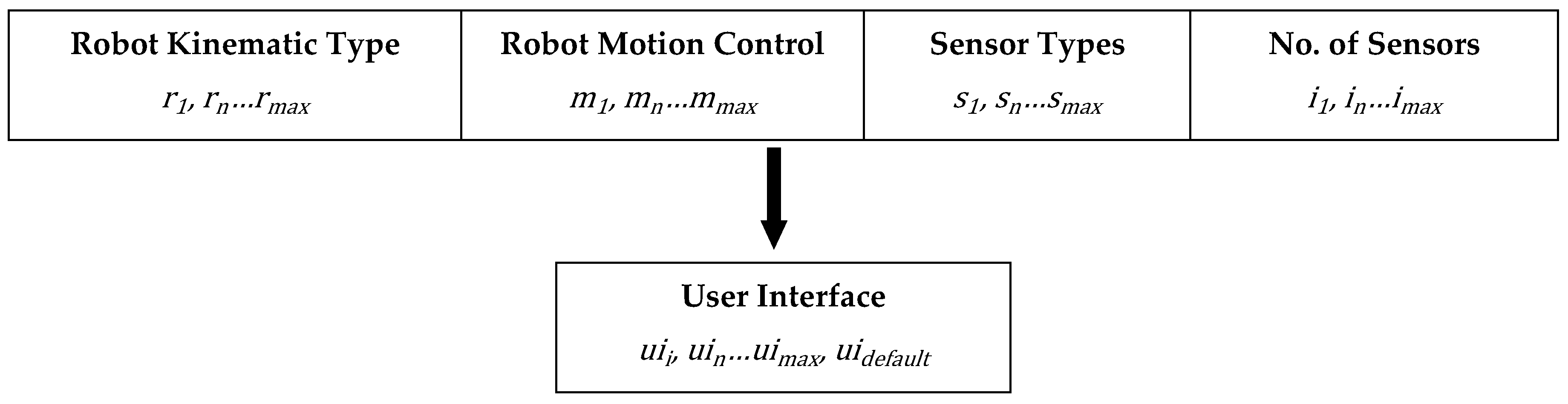
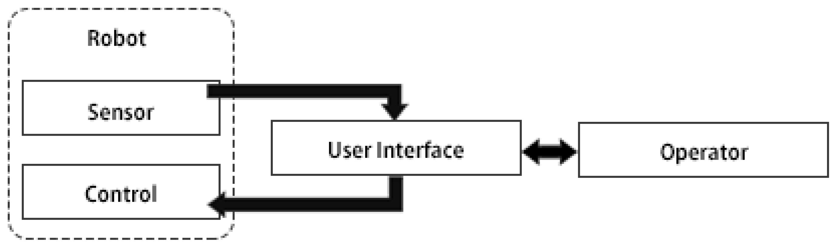
2.2. ROS Metadata and Teleoperation User Interface
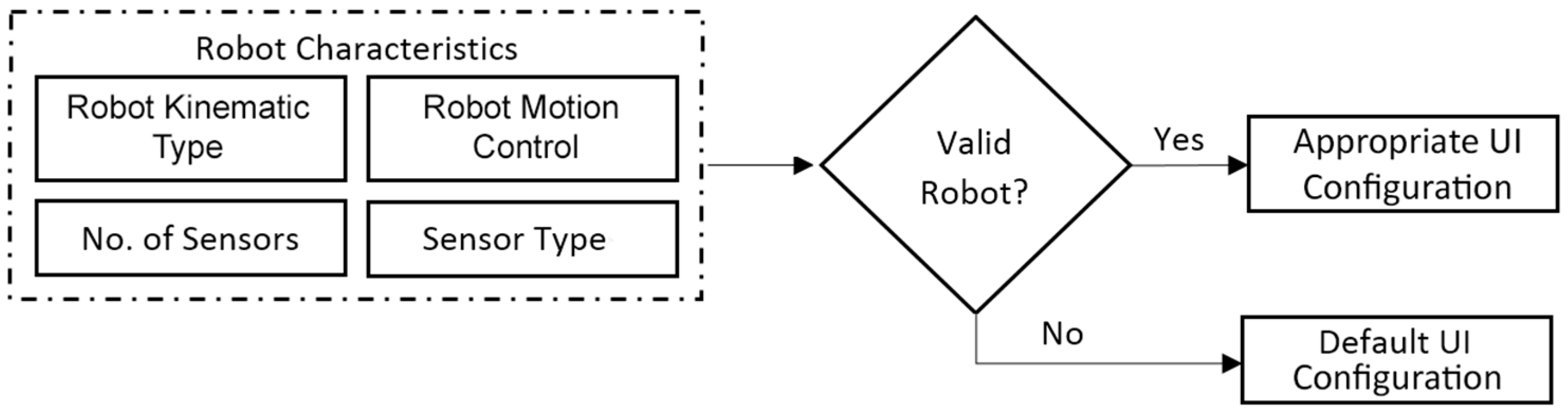
2.3. Relationship between ROS Metadata and Teleoperation User Interface
3. Materials and Methods
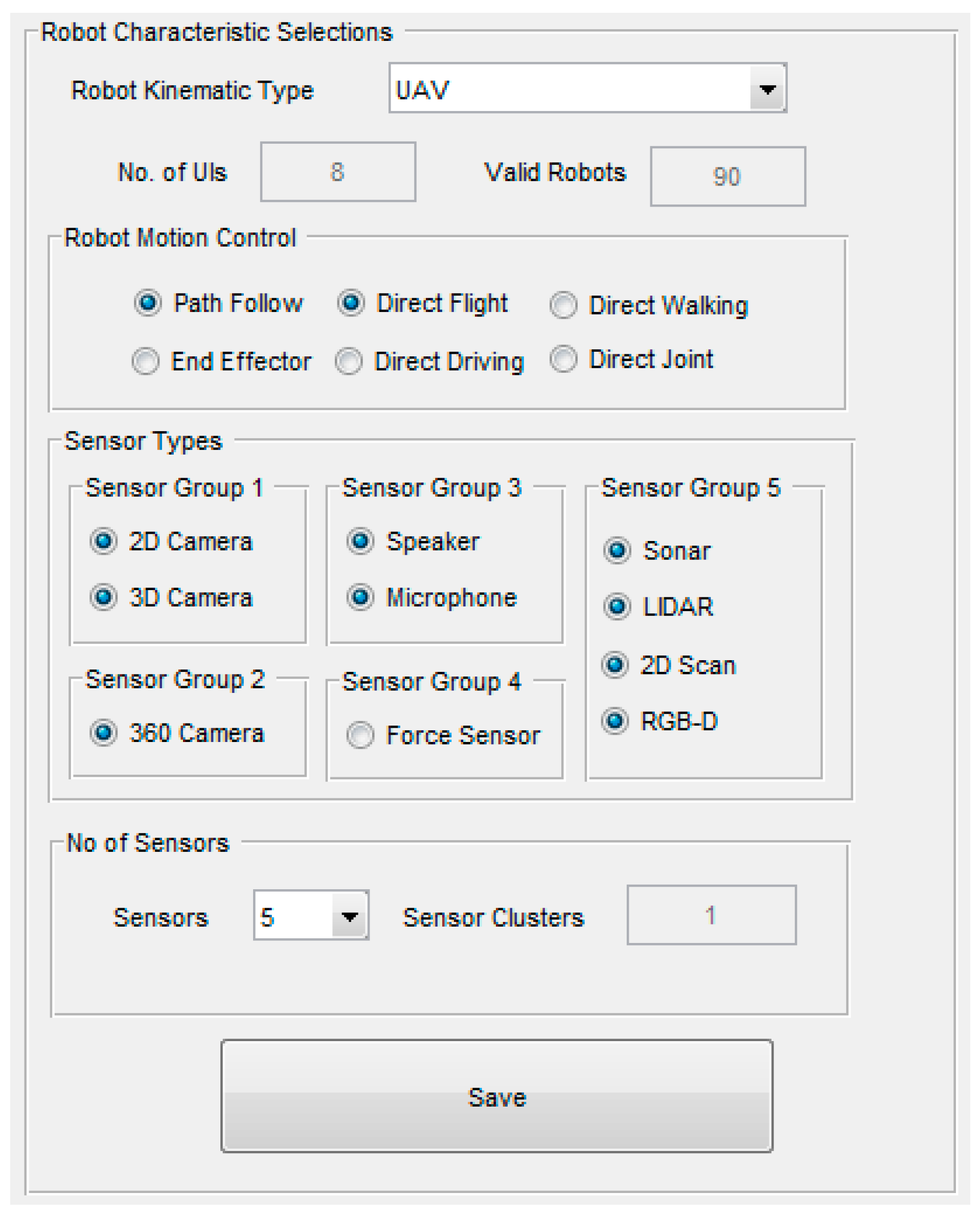
Matlab Toolbox
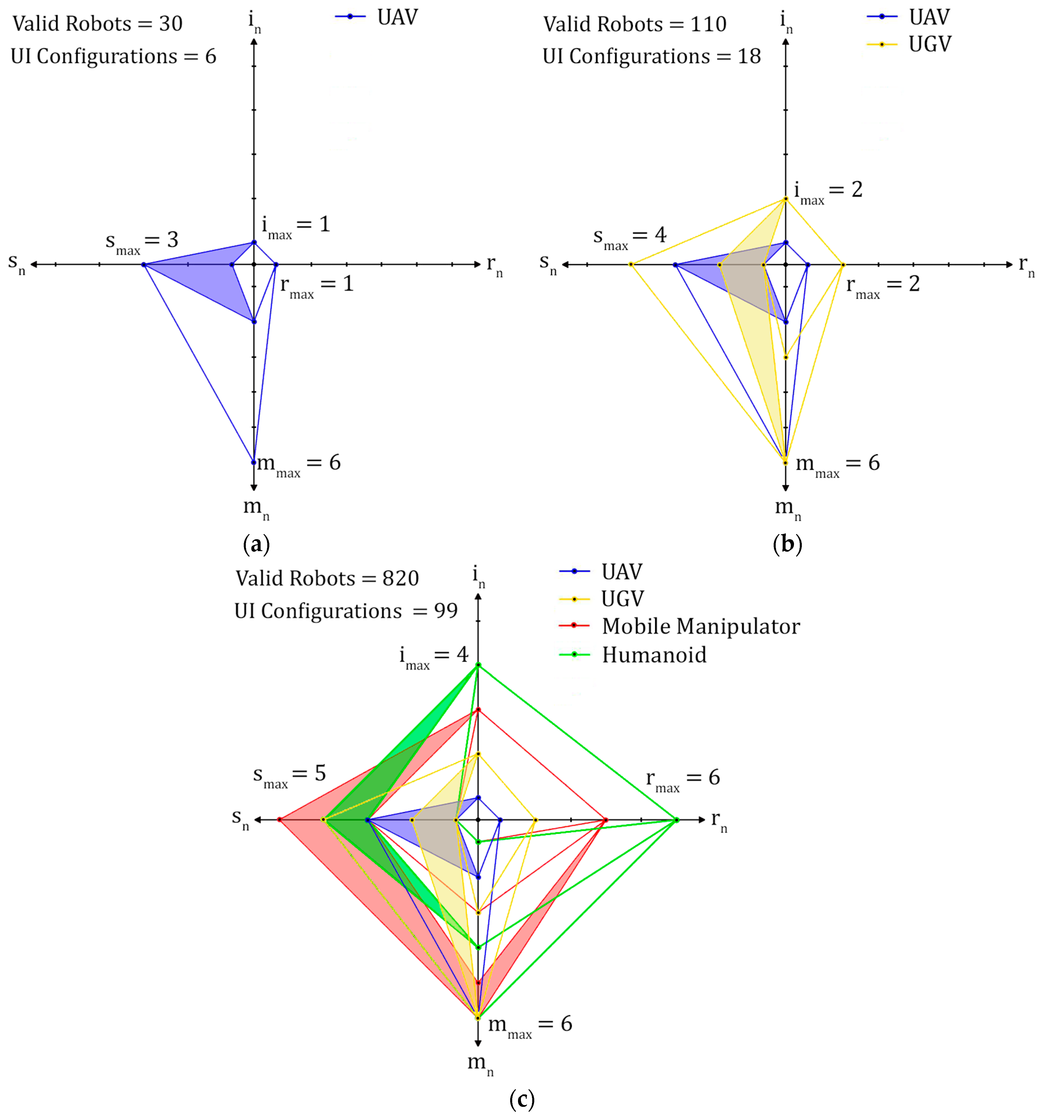
4. Results and Discussion
5. Conclusions and Future Work
Acknowledgments
Author Contributions
Conflicts of Interest
References
- Nagatani, K.; Kiribayashi, S.; Okada, Y.; Otake, K.; Yoshida, K.; Tadokoro, S.; Nishimura, T.; Yoshida, T.; Koyanagi, E.; Fukushima, M. Emergency response to the nuclear accident at the Fukushima Daiichi Nuclear Power Plants using mobile rescue robots. J. Field Robot. 2013, 30, 44–63. [Google Scholar] [CrossRef]
- Gómez-de-Gabriel, J.; Harwin, W. Evaluation of Sensor Configurations for Robotic Surgical Instruments. Sensors 2015, 15, 27341. [Google Scholar] [CrossRef] [PubMed]
- Dunbabin, M.; Marques, L. Robots for environmental monitoring: Significant advancements and applications. IEEE Robot. Autom. Mag. 2012, 19, 24–39. [Google Scholar] [CrossRef]
- Dolgov, D.; Thrun, S.; Montemerlo, M.; Diebel, J. Path planning for autonomous vehicles in unknown semi-structured environments. Int. J. Robot. Res. 2010, 29, 485–501. [Google Scholar] [CrossRef]
- Barrientos, A.; Colorado, J.; del Cerro, J.; Martinez, A.; Rossi, C.; Sanz, D.; Valente, J. Aerial remote sensing in agriculture: A practical approach to area coverage and path planning for fleets of mini aerial robots. J. Field Robot. 2011, 28, 667–689. [Google Scholar] [CrossRef]
- Quigley, M.; Conley, K.; Gerkey, B.; Faust, J.; Foote, T.; Leibs, J.; Wheeler, R.; Ng, A.Y. ROS: An Open-Source Robot Operating System. In Proceedings of the ICRA Workshop on Open Source Software, Kobe, Japan, 12–17 May 2009; p. 5.
- Cousins, S. ROS on the PR2 [ROS Topics]. IEEE Robot. Autom. Mag. 2010, 17, 23–25. [Google Scholar] [CrossRef]
- Agravante, D.J.; Pages, J.; Chaumette, F. Visual servoing for the REEM humanoid robot’s upper body. In Proceedings of the 2013 IEEE International Conference on Robotics and Automation (ICRA), Karlsruhe, Germany, 6–10 May 2013; pp. 5253–5258.
- Arumugam, R.; Enti, V.R.; Liu, B.; Wu, X.; Baskaran, K.; Kong, F.F.; Kumar, A.S.; Meng, K.D.; Kit, G.W. DAvinCi: A cloud computing framework for service robots. In Proceedings of the 2010 IEEE International Conference on Robotics and Automation (ICRA), Anchorage, AK, USA, 3–7 May 2010; pp. 3084–3089.
- Cousins, S. Exponential Growth of ROS [ROS Topics]. IEEE Robot. Autom. Mag. 2011, 18, 19–20. [Google Scholar]
- Badger, J.M.; Hart, S.W.; Yamokoski, J. Towards autonomous operation of robonaut 2. In Proceedings of the NASA, AIAA Infotech@ Aerospace 2012, Garden Grove, CA, USA, 19–21 June 2012.
- Chitta, S.; Sucan, I.; Cousins, S. MoveIt! [ROS TOPICS]. IEEE Robot. Autom. Mag. 2012, 19, 18–19. [Google Scholar] [CrossRef]
- Alexander, B.; Hsiao, K.; Jenkins, C.; Suay, B.; Toris, R. Robot Web Tools [ROS Topics]. IEEE Robot. Autom. Mag. 2012, 19, 20–23. [Google Scholar] [CrossRef]
- Crick, C.; Jay, G.; Osentoski, S.; Pitzer, B.; Jenkins, O.C. Rosbridge: Ros for non-ros users. In Proceedings of the 15th International Symposium on Robotics Research (ISRR), Flagstaff, AZ, USA, 9–12 December 2011.
- Hornung, A.; Wurm, K.M.; Bennewitz, M.; Stachniss, C.; Burgard, W. OctoMap: An efficient probabilistic 3D mapping framework based on octrees. Auton. Robot. 2013, 34, 189–206. [Google Scholar] [CrossRef]
- Santos, J.M.; Portugal, D.; Rocha, R.P. An evaluation of 2D SLAM techniques available in robot operating system. In Proceedings of the 2013 IEEE International Symposium on Safety, Security, and Rescue Robotics (SSRR), Linköping, Sweden, 21–26 October 2013; pp. 1–6.
- Chen, J.Y.C.; Haas, E.C.; Barnes, M.J. Human Performance Issues and User Interface Design for Teleoperated Robots. IEEE Trans. Syst. Man Cybern. 2007, 37, 1231–1245. [Google Scholar] [CrossRef]
- Liu, Y.; Nejat, G. Robotic Urban Search and Rescue: A Survey from the Control Perspective. J. Intell. Robot. Syst. 2013, 72, 147–165. [Google Scholar] [CrossRef]
- Velagapudi, P.; Scerri, P.; Sycara, K.; Wang, H.; Lewis, M.; Wang, J. Scaling effects in multi-robot control. In Proceedings of the 2008 IEEE/RSJ International Conference on Intelligent Robots and Systems, Nice, France, 22–26 September 2008; pp. 2121–2126.
- Hunziker, D.; Gajamohan, M.; Waibel, M.; D’Andrea, R. Rapyuta: The roboearth cloud engine. In Proceedings of the 2013 IEEE International Conference on Robotics and Automation (ICRA), Karlsruhe, Germany, 6–10 May 2013; pp. 438–444.
- Lazewatsky, D.A.; Smart, W.D. An inexpensive robot platform for teleoperation and experimentation. In Proceedings of the 2011 IEEE International Conference on Robotics and Automation (ICRA), Shanghai, China, 9–13 May 2011; pp. 1211–1216.
- Gossow, D.; Leeper, A.; Hershberger, D.; Ciocarlie, M. Interactive Markers: 3-D User Interfaces for ROS Applications [ROS Topics]. IEEE Robot. Autom. Mag. 2011, 18, 14–15. [Google Scholar] [CrossRef]
- Kruijff, G.-J.M.; Janíček, M.; Keshavdas, S.; Larochelle, B.; Zender, H.; Smets, N.J.; Mioch, T.; Neerincx, M.A.; Diggelen, J.; Colas, F. Experience in system design for human-robot teaming in urban search and rescue. In Field and Service Robotics; Springer: Berlin/Heidelberg, Germany, 2014; pp. 111–125. [Google Scholar]
- Waibel, M.; Beetz, M.; Civera, J.; d’Andrea, R.; Elfring, J.; Galvez-Lopez, D.; Haussermann, K.; Janssen, R.; Montiel, J.; Perzylo, A. A world wide web for robots. IEEE Robot. Autom. Mag. 2011, 18, 69–82. [Google Scholar] [CrossRef]
- Kunze, L.; Roehm, T.; Beetz, M. Towards semantic robot description languages. In Proceedings of the 2011 IEEE International Conference on Robotics and Automation (ICRA), Shanghai, China, 9–13 May 2011; pp. 5589–5595.
- Koenig, N.; Howard, A. Design and use paradigms for gazebo, an open-source multi-robot simulator. In Proceedings of the 2004 IEEE/RSJ International Conference on Intelligent Robots and Systems (IROS 2004), Sendai, Japan, 28 September–2 October 2004; pp. 2149–2154.
- Boumghar, R.; Lacroix, S.; Lefebvre, O. An information-driven navigation strategy for autonomous navigation in unknown environments. In Proceedings of the 2011 IEEE International Symposium on Safety, Security, and Rescue Robotics, Kyoto, Japan, 1–5 November 2011; pp. 172–177.
- Fung, W.; Lo, W.; Liu, Y.; Xi, N. A case study of 3D stereoscopic vs. 2D monoscopic tele-reality in real-time dexterous teleoperation. In Proceedings of the 2005 IEEE/RSJ International Conference on Intelligent Robots and Systems, Edmonton, AB, Canada, 2–6 August 2005; pp. 181–186.
- Mekonnen, A.A.; Briand, C.; Lerasle, F.; Herbulot, A. Fast HOG based person detection devoted to a mobile robot with a spherical camera. In Proceedings of the 2013 IEEE/RSJ International Conference on Intelligent Robots and Systems, Tokyo, Japan, 3–7 November 2013; pp. 631–637.
- Murphy, R.R.; Srinivasan, V.; Henkel, Z.; Suarez, J.; Minson, M.; Straus, J.C.; Hempstead, S.; Valdez, T.; Egawa, S. Interacting with trapped victims using robots. In Proceedings of the 2013 IEEE International Conference on Technologies for Homeland Security (HST), Waltham, MA, USA, 12–14 November 2013; pp. 32–37.
- Horan, B.; Nahavandi, S. Intuitive Haptic Control Surface for Mobile Robot Motion Control. In Proceedings of the 2008 IEEE International Workshop on Safety, Security and Rescue Robotics, Sendai, Japan, 21–24 October 2008; pp. 121–127.
- Saska, M.; Vonasek, V.; Krajnik, T.; Preucil, L. Coordination and navigation of heterogeneous UAVs-UGVs teams localized by a hawk-eye approach. In Proceedings of the 2012 IEEE/RSJ International Conference on Intelligent Robots and Systems (IROS), Vilamoura-Algarve, Portugal, 7–12 October 2012; pp. 2166–2171.
- Er, M.J.; Yuan, S.; Wang, N. Development control and navigation of Octocopter. In Proceedings of the 2013 10th IEEE International Conference on Control and Automation (ICCA), Hangzhou, China, 12–14 June 2013; pp. 1639–1643.
- Omari, S.; Hua, M.-D.; Ducard, G.; Hamel, T. Hardware and software architecture for nonlinear control of multirotor helicopters. IEEE/ASME Trans. Mechatron. 2013, 18, 1724–1736. [Google Scholar] [CrossRef]
- Kruijff, G.J.M.; Tretyakov, V.; Linder, T.; Pirri, F.; Gianni, M.; Papadakis, P.; Pizzoli, M.; Sinha, A.; Pianese, E.; Corrao, S.; et al. Rescue robots at earthquake-hit Mirandola, Italy: A field report. In Proceedings of the 2012 IEEE International Symposium on Safety, Security, and Rescue Robotics (SSRR), College Station, TX, USA, 5–8 November 2012; pp. 1–8.
- Kruckel, K.; Nolden, F.; Ferrein, A.; Scholl, I. Intuitive visual teleoperation for UGVs using free-look augmented reality displays. In Proceedings of the 2015 IEEE International Conference on Robotics and Automation (ICRA), Seattle, WA, USA, 26–30 May 2015; pp. 4412–4417.
- Kamali, K.; Joubair, A.; Bonev, I.A.; Bigras, P. Elasto-geometrical calibration of an industrial robot under multidirectional external loads using a laser tracker. In Proceedings of the 2016 IEEE International Conference on Robotics and Automation (ICRA), Stockholm, Sweden, 16–21 May 2016; pp. 4320–4327.
- Song, K.T.; Jiang, S.Y.; Lin, M.H. Interactive Teleoperation of a Mobile Manipulator Using a Shared-Control Approach. IEEE Trans. Hum.-Mach. Syst. 2016, PP, 1–12. [Google Scholar] [CrossRef]
- Aguilera-Marinovic, S.; Torres-Torriti, M.; Cheein, F.A. General Dynamic Model for Skid-Steer Mobile Manipulators with Wheel-Ground Interactions. IEEE/ASME Trans. Mechatron. 2016, PP, 433–444. [Google Scholar] [CrossRef]
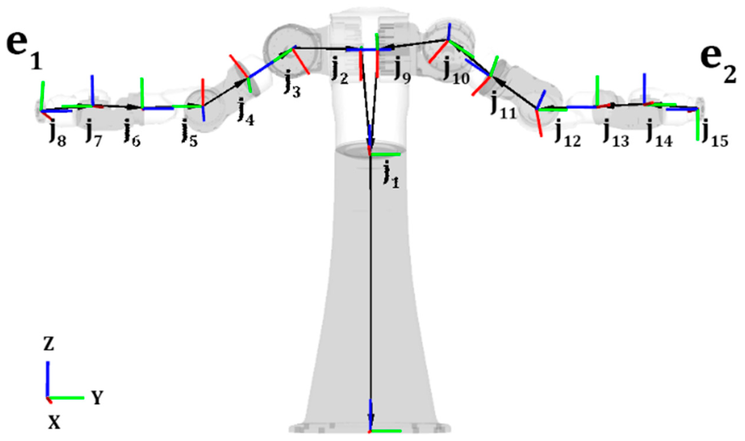
- Mortimer, M.; Horan, B.; Joordens, M.; Stojcevski, A. Searching Baxter’s URDF robot joint and link tree for active serial chains. In Proceedings of the 2015 10th System of Systems Engineering Conference (SoSE), San Antonio, TX, USA, 17–20 May 2015; pp. 428–433.
- Cela, A.; Yebes, J.; Arroyo, R.; Bergasa, L.; Barea, R.; López, E. Complete Low-Cost Implementation of a Teleoperated Control System for a Humanoid Robot. Sensors 2013, 13, 1385–1401. [Google Scholar] [CrossRef] [PubMed]
- Sian, N.E.; Yokoi, K.; Kajita, S.; Kanehiro, F.; Tanie, K. Whole body teleoperation of a humanoid robot-development of a simple master device using joysticks. In Proceedings of the IEEE/RSJ International Conference on Intelligent Robots and Systems, Lausanne, Switzerland, 30 September–4 October 2002; pp. 2569–2574.
- Shair, S.; Chandler, J.H.; Gonzalez-Villela, V.J.; Parkin, R.M.; Jackson, M.R. The Use of Aerial Images and GPS for Mobile Robot Waypoint Navigation. IEEE/ASME Trans. Mechatron. 2008, 13, 692–699. [Google Scholar] [CrossRef]


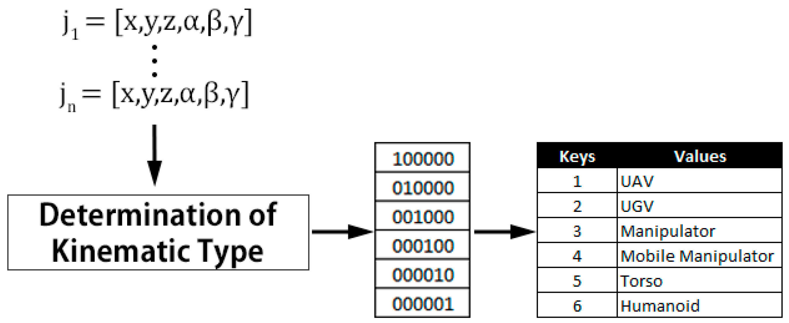
| Robot Kinematic Type | |
| UAV | Flying robot that includes quadcopters, hexacopters, and octocopters [32,33,34]. |
| UGV | Mobile robot that doesn’t contain any manipulators and uses either wheels or special tracks in order to navigate their terrain [35,36]. |
| Manipulator | Replicates an arm represented by a chain of joints between its base and end effector [37]. |
| Mobile Manipulator | A mobile manipulator is any robot that has at least one manipulator and has the ability to move around their environment using a mobile base [38,39]. |
| Torso | A torso robot typically replicates the upper half of a human body; it includes more than one manipulator, and doesn’t have the ability to navigate its environment through the likes of a mobile base [40]. |
| Humanoid | A humanoid robot is one that contains at least two arms, two legs, and a head closely replicating a human being; it may also consist of a waist joint [41]. |
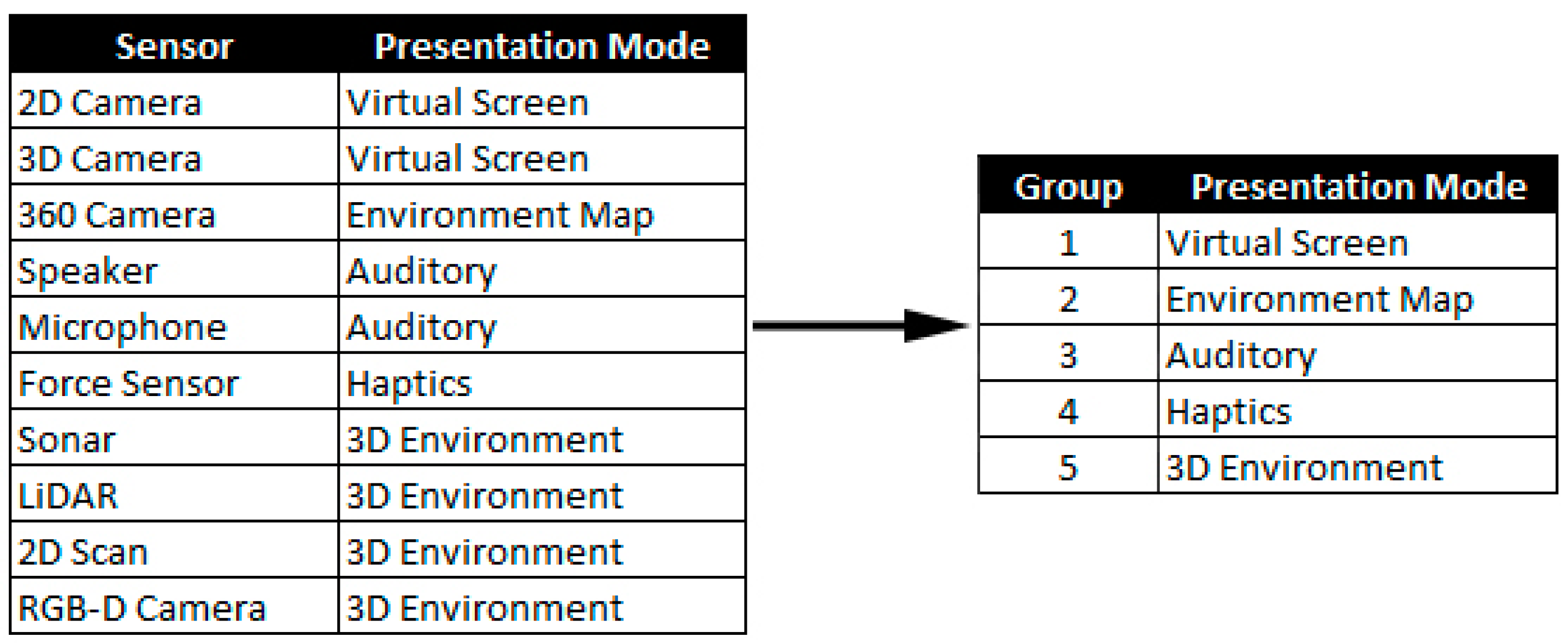
| Sensor Types | |
| 2D and 3D Cameras | Provides limited FoV, 3D cameras provide the added benefit of stereoscopic vision [28]. |
| 360° Camera | Provides complete 360° FoV generally overlaid on spherical geometry best viewed using a Head Mount Display (HMD) [29]. |
| Speaker and Microphone | Auditory sensors providing teleoperators the ability to listen and or communicate using sound [30]. |
| Force Sensor | Provide teleoperators force feedback information using a haptic device for physical interactions [31]. |
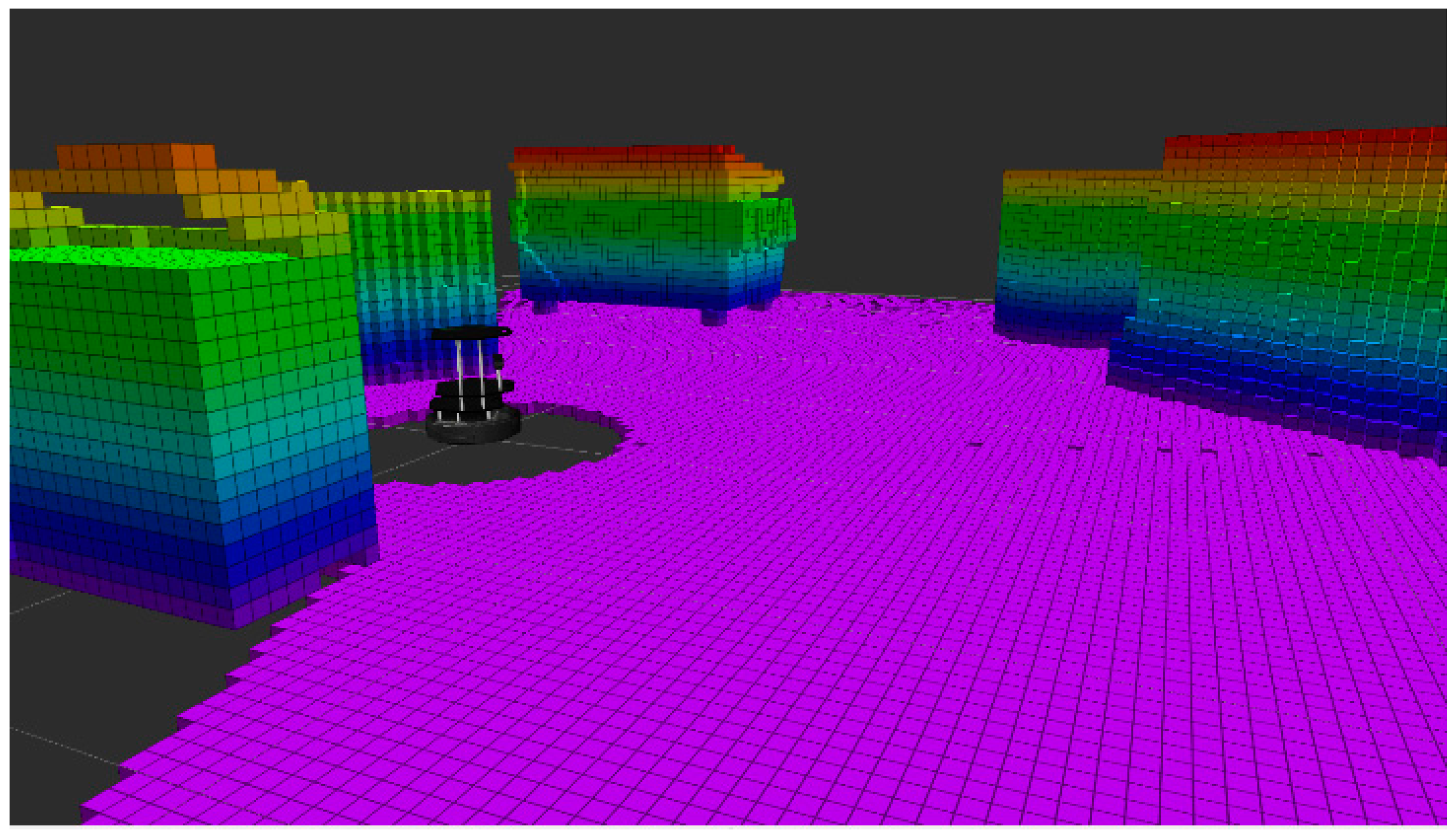
| 2D and 3D Scanning | Provide visual representation of the remote environment using point clouds that can be processed into solid objects and best viewed using a HMD similar to 360° cameras [15]. |
| Robot Motion Control | |
| Joint | Pure teleoperation used for individual joint control [22]. |
| Flight | Used to fly UAVs as a pure teleoperation with yaw, pitch and roll controls. |
| Driving | Used to control UGV, mobile bases, etc. typically has backward, forward and turning controls. |
| Walking | Pure teleoperation method for a teleoperator to control the direction and pace of a given humanoid [42]. |
| End Effector | Used to position the end effectors of manipulators; could be used in combination of object identification to pick and place particular objects [12]. |
| Waypoint | Waypoint provides the teleoperator the ability to select a particular location for example a GPS coordinate on a map; the robot then has the ability to navigate to the point using its own path finding techniques [43]. |
| Case | Robot Kinematic Type | Robot Motion Control | Sensor Types | No. of Sensors |
|---|---|---|---|---|
| 1 | UAV | Flight Waypoint | 2D Camera 360° Camera RGB-D Camera | 5 |
| 2 | UAV | Flight Waypoint | 2D Camera 360° Camera RGB-D Camera | 5 |
| UGV | Driving Waypoint | 2D Camera LIDAR Speaker Microphone | 10 | |
| 3 | UAV | Flight Waypoint | 2D Camera 360° Camera RGB-D Camera | 5 |
| UGV | Driving Waypoint | 2D Camera LIDAR Speaker Microphone | 10 | |
| Mobile Manipulator | Joint Driving End Effector Waypoint | 2D Camera RGD-D Camera LIDAR Speaker Microphone Force Sensor | 13 | |
| Humanoid | Joint Walking Waypoint | 2D Camera 3D Camera LIDAR RGB-D Camera Speaker Microphone | 25 |
© 2017 by the authors. Licensee MDPI, Basel, Switzerland. This article is an open access article distributed under the terms and conditions of the Creative Commons Attribution (CC BY) license ( http://creativecommons.org/licenses/by/4.0/).
Share and Cite
Mortimer, M.; Horan, B.; Seyedmahmoudian, M. Building a Relationship between Robot Characteristics and Teleoperation User Interfaces. Sensors 2017, 17, 587. https://doi.org/10.3390/s17030587
Mortimer M, Horan B, Seyedmahmoudian M. Building a Relationship between Robot Characteristics and Teleoperation User Interfaces. Sensors. 2017; 17(3):587. https://doi.org/10.3390/s17030587
Chicago/Turabian StyleMortimer, Michael, Ben Horan, and Mehdi Seyedmahmoudian. 2017. "Building a Relationship between Robot Characteristics and Teleoperation User Interfaces" Sensors 17, no. 3: 587. https://doi.org/10.3390/s17030587
APA StyleMortimer, M., Horan, B., & Seyedmahmoudian, M. (2017). Building a Relationship between Robot Characteristics and Teleoperation User Interfaces. Sensors, 17(3), 587. https://doi.org/10.3390/s17030587