Abstract
Recently, the stereo imaging-based image enhancement approach has attracted increasing attention in the field of video analysis. This paper presents a dual camera-based stereo image defogging algorithm. Optical flow is first estimated from the stereo foggy image pair, and the initial disparity map is generated from the estimated optical flow. Next, an initial transmission map is generated using the initial disparity map. Atmospheric light is then estimated using the color line theory. The defogged result is finally reconstructed using the estimated transmission map and atmospheric light. The proposed method can refine the transmission map iteratively. Experimental results show that the proposed method can successfully remove fog without color distortion. The proposed method can be used as a pre-processing step for an outdoor video analysis system and a high-end smartphone with a dual camera system.
1. Introduction
Image analysis using multiple images has recently attracted growing attention in the fields of autonomous driving, unmanned surveillance cameras, and drone imaging service. It is important to acquire additional depth information as well as high-quality images in many sophisticated image analysis applications. Another market-leading application is the dual camera in a smartphone. The proposed stereo image-based defogging algorithm can be applied to an asymmetric dual camera system in a smartphone with a proper geometric transformation to improve the visibility of the outdoor foggy scene acquired by a smartphone. Specifically, fog component in the atmosphere decreases contrast, and as a result, makes extracting features or recognizing objects in image analysis difficult. Therefore, an image enhancement method to reduce the fog component is important to increase the reliability of the image analysis system.
Fog particles absorb and scatter the light reflected from the object and then transmitted to the camera. They also distort the original color and edge in a random manner. The amount of atmospheric distortion increases with the distance between a scene point and the camera. This phenomenon can be quantified using a transmission coefficient at each pixel. For this reason, the degraded foggy image is modeled as a combination of the original reflectance of the scene, the atmospheric component, and the transmission coefficient in a pixel-wise manner. Because of its importance in various image analysis applications, the image defogging problem has been intensively studied in the field of image processing and computer vision.
Narasimhan et al. corrected color distortion by estimating the distribution of fog according to the distance [1,2]. They acquired multiple images of the same scene under different weather conditions to construct a scene structure. Shwartz et al. and Schechner et al. proposed a defogging method by measuring the distribution of fog using two different polarized filters in the same scene [3,4]. These methods can successfully remove the fog component using a physically reasonable degradation model at the cost of inconvenience to acquire multiple images of the same scene.
To solve these problems, various single image defogging methods were proposed. Tan proposed a defogging method using the characteristics that a fog-free image has higher contrast than foggy images and color distortion caused by fog increases proportionally to the distance from the camera [5]. Based on these two characteristics, the Markov random field model was estimated and a fog-free image was obtained by maximizing the local contrast at the cost of contrast saturation and halo effect. Fattal removed fog using the property that the surface reflectance of the object is constant and the transmission depends on the density and depth information fog [6]. However, it is difficult to measure the reflectance in a region of dense fog. He et al. proposed a method of estimating the transmission map using the dark channel prior (DCP) [7]. The DCP theory is based on the observation that the minimum intensity of one of the RGB channels in a fog-free region is close to zero. However, it cannot avoid color distortion, since the transmission map is estimated using the color of the object. In addition, in order to remove the blocking and the halo effects appearing in the process of estimating the transmission map, a computationally expensive soft-matting algorithm is used. To solve this problem, Gibson et al. replaced the soft-matting step with a standard median filter [8], Xiao et al. removed the blocking and halo effects using a joint bilateral filtering [9], Chen et al. used a gain intervention refinement filter [10], and Jha et al. used an norm prior [11]. Yoon et al. proposed a defogging method using the multiphase level set in the HSV color space and corrected colors between adjacent video frames [12]. Meng et al. proposed a method to estimate the transmission map using a boundary constraint, and they refined the transmission map through norm-based regularization [13]. Ancuti et al. proposed a multiscale fusion-based defogging algorithm using a Laplacian pyramid and a Gaussian pyramid, both of which improved a single foggy image using white balance and contrast enhancement, respectively [14]. Berman et al. proposed a nonlocal-based defogging algorithm using an estimated transmission based on color lines [15]. However, these methods are not free from color distortion, since they do not consider the depth information. Recently, several learning-based defogging methods have been proposed [16,17,18,19]. Chen et al. proposed a radial basis function (RBF) network to restore a foggy image while recovering visible edges [16]. Cai et al. proposed a trainable end-to-end system to estimate the medium transmission, called DehazeNet [17]. Eigen et al. proposed a convolutional neural network (CNN) architecture to remove raindrop and lens dirt [19].
Many defogging methods were proposed using the depth information. Caraffa et al. proposed a depth-based defogging method using Markov random field model to generate the disparity map using a stereo image pair [20]. Lee et al. estimated the scattering coefficient of the atmosphere in the stereo image [21]. Park et al. estimated the depth in the stereo image pair and removed the fog by estimating the atmospheric light in the farthest region [22]. However, accurate estimation of the transmission map is still an open problem, since the features for obtaining the disparity map are generally distorted in the foggy image.
To improve the problem of existing single-image-based defogging algorithms, this paper presents a novel image defogging algorithm using a stereo foggy image pair. The proposed defogging algorithm removes fog by estimating the depth information from the stereo image pair and iteratively improving the depth information. The disparity of an input stereo foggy image pair is first obtained using the optical flow, and the depth map is generated using the disparity. Next, the transmission map is estimated using the generated depth map to remove the foggy component. The optical flow and transmission map estimation steps repeat until the defogged solution converges. The proposed stereo-based defogging algorithm is suitable for dual cameras embedded in high-end smartphone models that were recently released on the consumer market.
The paper is organized as follows: Section 2 describes a physical degradation model for foggy image acquisition, and Section 3 presents the proposed stereo-based defogging algorithm based on the degradation model. Section 4 summarizes experimental results, Section 5 presents an application of the proposed defogging algorithm to an asymmetric dual camera system, and Section 6 concludes the paper.
2. Physical Degradation Model of Foggy Image Acquisition
Figure 1 shows the physical degradation model of foggy image acquisition. The light reflected by the object is absorbed and scattered by fog particles in the atmosphere, and arrives at the camera sensor. Therefore, the greater the distance between the object and the camera is, the greater the atmospheric degradation becomes. The foggy image g is defined according to the Koschmieder model [23] as
where represents the pixel coordinate, the fog-free image, and the constant A the global atmospheric light. represents the transmission coefficient at pixel , and can be expressed as
where represents the scattering coefficient of the atmosphere, and the depth between the scene point and the camera. From (1) , an intuitive estimation of the fog-free image is given as
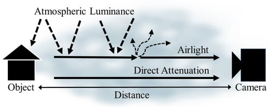
Figure 1.
Illustration of the foggy image formation model.
The defogged image is obtained by substituting the estimated A and into (3). is the lower bound of , which is set to an arbitrary value to avoid the zero in the denominator.
3. Image Defogging Based on Iteratively Refined Transmission
Most existing defogging algorithms estimate the disparity map from the stereo foggy image pair, and then obtain the defogged image by estimating the transmission map using (2). However, it is difficult to detect the feature to estimate the disparity map, since the foggy image is distorted by the fog component. To solve this problem, the proposed algorithm estimates an accurate transmission map by iteratively improving the disparity map. The disparity map is generated by estimating optical flow from the stereo foggy image pair, and the initial transmission map is generated by the disparity. Atmospheric light A is estimated using the color line theory [24], and each stereo foggy image is restored using (3). By repeating the set of optical flow estimation, transmission map generation and defogging steps, a progressively improved transmission map and better defogged image are obtained. This process repeats until the absolute difference between the kth and ()th defogged images is less than a pre-specified threshold . Figure 2 shows the block diagram of the proposed algorithm.
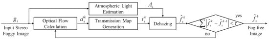
Figure 2.
Block diagram of the proposed defogging algorithm: For , is the input stereo image pair, is the global atmospheric light, , , and , respectively, are the disparity map, the transmission map, and the defogged image at the k-th iteration.
3.1. Atmospheric Light Estimation
Most single-image-based defogging algorithms set the atmospheric light A to an arbitrary constant or to the brightest pixel value in the image under the assumption that the fog color is white [5,6,7]. Since these methods do not estimate the accurate atmospheric light, the quality of defogged images is degraded. In this paper, the atmospheric light A is estimated using the color line-based estimation method that was originally proposed by Sulami et al. [25].
In (1), the fog-free image can be expressed as
where surface shading is a scalar value indicating the magnitude of the reflected light, and surface albedo is an RGB vector representing the chromaticity of the reflected light. In general, when a natural image is divided into small patches, the surface albedo and transmission of each image patch are approximately constant. Therefore, using this characteristic and (4), the foggy image formation model in (1) can be expressed as follows:
where represents the transmission value of the i-th image patch, the surface albedo of the patch. To create color lines in the RGB color space using image patches with the same surface albedo and transmission, image patches satisfying (5) are selected using principal component analysis (PCA). The strongest principal axis of the image patch should correspond to the orientation of the color line, and there should be a single significant principal component. Additionally, the color line of the image patch should not pass the origin in RGB space, and the image patch should not contain an edge. The color lines are generated using image patches that satisfy these conditions, and the orientation and magnitude of vector A is estimated.
3.2. Stereo Image Defogging
To generate the transmission of a stereo image pair, the disparity map is estimated using the combined local–global approach with total variation (CLG–TV) [26]. The CLG–TV approach integrates Lucas–Kanade [27] and Horn–Schunck [28] models to estimate motion boundary-preserved optical flow using a variational method. The norm error function of the Horn–Schunck model is defined as
where represents the residual between the left and right images as
where is the optical flow to estimate with the initial value , and the left and right images are respectively given as
where , can be minimized by solving the Euler–Lagrange equation using Jacobi iteration. To make the estimated optical flow as uniform as possible in a small region, the residual in (6) is substituted by the Lucas–Kanade error function
where w represents the weighting factor. is minimized solving a least-squares problem. Based on the Lucas–Kanade model, the total error of the same window is minimized. The following error function combines Horn–Schunck and Lucas–Kanade models.
To solve the over-smoothing problem in motion boundaries regions, the norm is minimized instead of the norm.
To minimize the CLG–TV error function, we use an alternative Horn–Schunck model [29] where is decomposed into three terms, as shown below.
is minimized in the point-wise manner, whereas and are minimized using the procedure proposed by Chambolle [30]. In this paper, we calculated the disparity map for only u from the stereo image.
Figure 3 shows the result of the transmission map estimation and fog removal using a stereo input image pair. Since the disparity map is generated using the distorted features by foggy component, the initially estimated transmission map is not sufficiently clear.
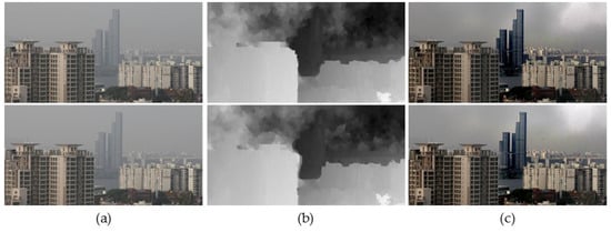
Figure 3.
Results of defogging using the initial transmission map. (a) A stereo pair of input foggy images; (b) initial transmission maps; and (c) defogged results.
3.3. Iterative Refinement of Transmission Map
In this subsection, an iterative process is performed to refine the transmission map. The disparity map is estimated again on the defogged image , estimated by using the initial transmission map , and the transmission map is updated. The kth defogged image is obtained by the updated transmission map .
Figure 4 shows the estimated transmission map and the result of fog removal through the iterative process. As shown in Figure 4, color distortion in the sky region is gradually reduced.
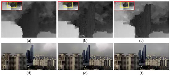
Figure 4.
Iterative refinement process of transmission map. (a–c) The 1-st, 3-rd, and 5-th refined transmission maps; and (d–f) the 1-st, 3-rd, and 5-th defogged results.
Figure 5 shows the iteratively refined transmission maps and the correspondingly defogged results using the FRIDA3 dataset (Foggy Road Image DAtabase) [20]. As the fog is removed in the distant region, the transmission map is gradually improved in the iterative process. As a result, the red circle region is iteratively improved and the initially invisible vehicle appears.
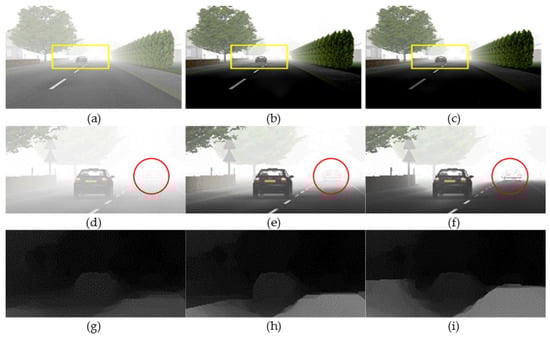
Figure 5.
Defogging results of synthetic stereo image. (a–c) Input, 4-, and 7-th defogged images; (d–f) enlarged version of (a–c); and (g–i) corresponding transmission maps.
Figure 6 shows the iteratively defogged results using real-world videos [31]. We extracted two adjacent frames in a video and assumed a situation of acquiring images using a dual camera. In the iteration process, the transmission map is gradually refined, and the defogged result is improved.
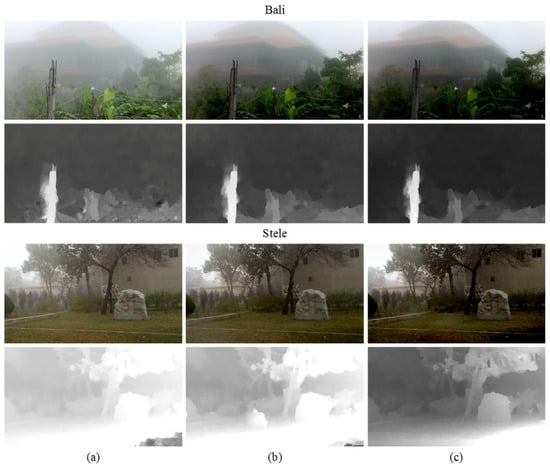
Figure 6.
Defogging results using real-world videos from [31]. (a) Input foggy images; (b) defogged results after three iterations; and (c) defogged results after five iterations. Corresponding transmission maps are shown below each image.
4. Experimental Results
To evaluate the performance of the proposed defogging method, experimental results are compared with those of the state-of-the-art defogging algorithms. Figure 7a shows a set of test foggy images, Figure 7b–f respectively shows results of He’s method [7], Ancuti’s method [14], Meng’s method [13], Berman’s method [15], and the proposed method.
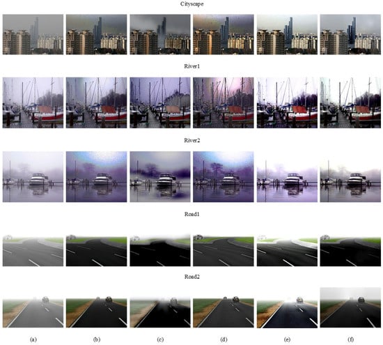
Figure 7.
Experimental results of various defogging methods. (a) Input foggy images; (b) He et al. [7]; (c) Ancuti et al. [14]; (d) Meng et al. [13]; (e) Berman et al. [15]; (f) the proposed method.
In Cityscape, River1, and River2 results, Figure 7b,d shows that color distortion and low saturation artifacts occur in the sky region because the atmospheric light is not accurately estimated. Figure 7c shows that the color of the sky region is distorted and the color around the building is faded because the same amount of fog is removed without considering spatially different depth information. Figure 7e shows a slight amount of color distortion since the initial transmission map is regularized by using Gaussian Markov random fields with only local neighbors. Figure 7f shows that the defogged result is clearer than any other method in the sky region, and the color contrast is increased.
In Road1 and Road2 results, Figure 7c shows that the color around the road is faded and distorted because it does not consider depth information. Figure 7e shows that the color tends to be oversaturated when the atmosphere light is significantly brighter than the scene. Figure 7b,d shows excellent defogging results because the color of artificially added fog is mostly white, so the transmission map is well estimated by the DCP-based defogging algorithm. Figure 7f shows a well-defogged result without color distortion or saturation. Experimental results demonstrated that the proposed algorithm outperforms existing algorithms in terms of both fog removal and color preservation.
Table 1 shows two quantitative measures for objective evaluation, including no-reference image quality metric for contrast distortion (NIQMC) [32] and entropy for measuring contrast of the defogged results. The higher NIQMC value indicates superior color contrast and edge of the image. A high entropy value indicates that the average amount of information in the image is high. In other words, a greater amount of information about the edges or features results in better color contrast. Based on Table 1, the highest values in each image are shown in bold and the proposed method performs better than other existing methods.

Table 1.
Quantitative results for each method using stereo images. NIQMC: no-reference image quality metric for contrast distortion.
5. Application to Asymmetric Dual Camera System
The proposed stereo-based defogging algorithm is particularly suitable for a dual camera system that has attracted increasing attention in the field of robot vision, autonomous driving, and high-end smartphones. Figure 8 shows the block diagram of the proposed defogging algorithm applied to an asymmetric dual camera system. To estimate the depth information, features in the stereo foggy image pair are first matched, and the scale of the longer focal length image is then corrected. The proposed defogging method is applied to the overlapped regions of two images with different focal lengths. To remove the fog in the non-overlapping region, a single image-based defogging method is first used, and color distortion is then corrected using histogram matching with reference to the overlapped region.
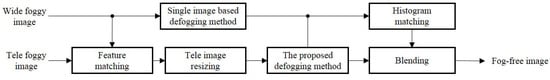
Figure 8.
Block diagram of the proposed defogging algorithm applied to an asymmetric dual camera system.
Figure 9 demonstrates that the proposed algorithm can be applied to an asymmetric dual camera system. For the experiment, Figure 9b is obtained by cropping the center region of Figure 9a. As a result, Figure 9a,b can be considered as a stereo pair of input foggy images with different focal lengths. Figure 9c shows the defogged result of Figure 9a by the single image defogging method. Figure 9d shows the defogged result of Figure 9b by the stereo image defogging method proposed in this paper. Figure 9e shows the stitching result of Figure 9c,d. Based on the result, the proposed stereo-based method can remove fog while preserving the original color information in the asymmetric dual camera system.
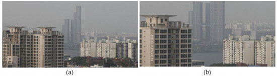
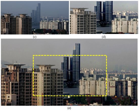
Figure 9.
Defogging results using a simulated pair of dual camera images. (a) An input foggy image; (b) simulated longer focal length; (c) defogged version of (a) using a single-image-based method; (d) defogged version of (b) using the proposed stereo-based method; (e) stitched result of (c,d).
6. Conclusions
In this paper, a stereo defogging algorithm is proposed to accurately estimate the transmission map based on the depth information. The major contribution of this work is twofold: (i) The stereo-based iterative defogging process can provide greatly enhanced results compared with existing state-of-the-art methods; and (ii) the framework of the stereo-based algorithm is particularly suitable for a dual camera system that is embedded in a high-end consumer smartphone. The proposed method first obtains the disparity map by estimating optical flow from the stereo foggy image pair, and generates the initial transmission map using the disparity. The defogged image is restored by generating the transmission map and estimating atmospheric light A based on the color line theory. By repeating the set of optical flow estimation, transmission map generation, and defogging until convergence, significantly improved defogged results were obtained. Experimental results show that the proposed method successfully removed fog without color distortion, and the transmission map and the defogged image were iteratively refined. The proposed method can be used as a pre-processing step for an outdoor image analysis function in an intelligent video surveillance system, autonomous driving, and asymmetric dual camera in a high-end smartphone.
Acknowledgments
This work was supported by the Institute for Information & communications Technology Promotion (IITP) grant funded by the Korea government (MSIT) (2017-0-00250, Intelligent Defense Boundary Surveillance Technology Using Collaborative Reinforced Learning of Embedded Edge Camera and Image Analysis).
Author Contributions
Heegwang Kim performed the experiments. Jinho Park and Hasil Park initiated the research and designed the experiments. Joonki Paik wrote the paper.
Conflicts of Interest
The authors declare no conflict of interest.
References
- Narasimhan, S.G.; Nayar, S.K. Vision and the Atmosphere. Int. J. Comput. Vis. 2002, 48, 233–254. [Google Scholar] [CrossRef]
- Narasimhan, S.G.; Nayar, S.K. Contrast restoration of weather degraded images. IEEE Trans. Pattern Anal. Mach. Intell. 2003, 25, 713–724. [Google Scholar] [CrossRef]
- Shwartz, S.; Namer, E.; Schechner, Y.Y. Blind Haze Separation. In Proceedings of the 2006 IEEE Computer Society Conference on Computer Vision and Pattern Recognition (CVPR’06), New York, NY, USA, 17–22 June 2006; Volume 2, pp. 1984–1991. [Google Scholar]
- Schechner, Y.Y.; Narasimhan, S.G.; Nayar, S.K. Instant dehazing of images using polarization. In Proceedings of the 2001 IEEE Computer Society Conference on Computer Vision and Pattern Recognition, Kauai, HI, USA, 8–14 December 2001; Volume 1. [Google Scholar]
- Tan, R.T. Visibility in bad weather from a single image. In Proceedings of the 2008 IEEE Conference on Computer Vision and Pattern Recognition, Anchorage, AK, USA, 23–28 June 2008; pp. 1–8. [Google Scholar]
- Fattal, R. Single Image Dehazing. ACM Trans. Graph. 2008, 27, 72:1–72:9. [Google Scholar] [CrossRef]
- He, K.; Sun, J.; Tang, X. Single Image Haze Removal Using Dark Channel Prior. IEEE Trans. Pattern Anal. Mach. Intell. 2011, 33, 2341–2353. [Google Scholar] [PubMed]
- Gibson, K.B.; Vo, D.T.; Nguyen, T.Q. An investigation of dehazing effects on image and video coding. IEEE Trans. Image Process. 2012, 21, 662–673. [Google Scholar] [CrossRef] [PubMed]
- Xiao, C.; Gan, J. Fast image dehazing using guided joint bilateral filter. Vis. Comput. 2012, 28, 713–721. [Google Scholar]
- Chen, B.H.; Huang, S.C.; Cheng, F.C. A high-efficiency and high-speed gain intervention refinement filter for haze removal. J. Disp. Technol. 2016, 12, 753–759. [Google Scholar] [CrossRef]
- Jha, D.K. l2-norm-based prior for haze-removal from single image. IET Comput. Vis. 2016, 10, 331–343. [Google Scholar] [CrossRef]
- Yoon, I.; Kim, S.; Kim, D.; Hayes, M.H.; Paik, J. Adaptive defogging with color correction in the HSV color space for consumer surveillance system. IEEE Trans. Consum. Electron. 2012, 58, 111–116. [Google Scholar] [CrossRef]
- Meng, G.; Wang, Y.; Duan, J.; Xiang, S.; Pan, C. Efficient Image Dehazing with Boundary Constraint and Contextual Regularization. In Proceedings of the 2013 IEEE International Conference on Computer Vision, Sydney, Australia, 1–8 December 2013; pp. 617–624. [Google Scholar]
- Ancuti, C.O.; Ancuti, C. Single Image Dehazing by Multi-Scale Fusion. IEEE Trans. Image Process. 2013, 22, 3271–3282. [Google Scholar] [CrossRef] [PubMed]
- Berman, D.; Treibitz, T.; Avidan, S. Non-local Image Dehazing. In Proceedings of the 2016 IEEE Conference on Computer Vision and Pattern Recognition (CVPR), Las Vegas, NV, USA, 27–30 June 2016; pp. 1674–1682. [Google Scholar]
- Chen, B.H.; Huang, S.C.; Li, C.Y.; Kuo, S.Y. Haze removal using radial basis function networks for visibility restoration applications. IEEE Trans. Neural Netw. Learn. Syst. 2017, 1–11. [Google Scholar] [CrossRef] [PubMed]
- Cai, B.; Xu, X.; Jia, K.; Qing, C.; Tao, D. Dehazenet: An end-to-end system for single image haze removal. IEEE Trans. Image Process. 2016, 25, 5187–5198. [Google Scholar]
- Chen, B.H.; Huang, S.C.; Kuo, S.Y. Error-Optimized Sparse Representation for Single Image Rain Removal. IEEE Trans. Ind. Electron. 2017, 64, 6573–6581. [Google Scholar] [CrossRef]
- Eigen, D.; Krishnan, D.; Fergus, R. Restoring an image taken through a window covered with dirt or rain. In Proceedings of the IEEE International Conference on Computer Vision, Sydney, Australia, 1–8 December 2013; pp. 633–640. [Google Scholar]
- Caraffa, L.; Tarel, J.P. Stereo Reconstruction and Contrast Restoration in Daytime Fog. In Revised Selected Papers, Part IV, Proceedings of the Computer Vision—ACCV 2012: 11th Asian Conference on Computer Vision, Daejeon, Korea, 5–9 November 2012; Lee, K.M., Matsushita, Y., Rehg, J.M., Hu, Z., Eds.; Springer: Berlin/Heidelberg, Germany, 2013; pp. 13–25. [Google Scholar]
- Lee, Y.; Gibson, K.B.; Lee, Z.; Nguyen, T.Q. Stereo image defogging. In Proceedings of the 2014 IEEE International Conference on Image Processing (ICIP), Paris, France, 27–30 October 2014; pp. 5427–5431. [Google Scholar]
- Park, H.; Park, J.; Kim, H.; Paik, J. Improved DCP-based image defogging using stereo images. In Proceedings of the 2016 IEEE 6th International Conference on Consumer Electronics, Berlin, Germany, 5–7 September 2016; pp. 48–49. [Google Scholar]
- Koschmieder, H. Theorie der horizontalen sichtweite. Beitrage Physik Freien Atmosphare 1924, 12, 33–53. [Google Scholar]
- Omer, I.; Werman, M. Color lines: Image specific color representation. In Proceedings of the 2004 IEEE Computer Society Conference on Computer Vision and Pattern Recognition, Washington, DC, USA, 27 June–2 July 2004; Volume 2. [Google Scholar]
- Sulami, M.; Glatzer, I.; Fattal, R.; Werman, M. Automatic recovery of the atmospheric light in hazy images. In Proceedings of the 2014 IEEE International Conference on Computational Photography (ICCP), Santa Clara, CA, USA, 2–4 May 2014; pp. 1–11. [Google Scholar]
- Drulea, M.; Nedevschi, S. Total variation regularization of local-global optical flow. In Proceedings of the 14th International IEEE Conference on Intelligent Transportation Systems (ITSC), Washington, DC, USA, 5–7 October 2011; pp. 318–323. [Google Scholar]
- Lucas, B.D.; Kanade, T. An iterative image registration technique with an application to stereo vision. In Proceedings of the 7th International Joint Conference on Artificial Intelligence, Vancouver, BC, Canada, 24–28 August 1981. [Google Scholar]
- Horn, B.K.; Schunck, B.G. Determining optical flow. Artif. Intell. 1981, 17, 185–203. [Google Scholar] [CrossRef]
- Zach, C.; Pock, T.; Bischof, H. A duality based approach for realtime TV-L1 optical flow. Pattern Recognit. 2007, 4713, 214–223. [Google Scholar]
- Chambolle, A. An algorithm for total variation minimization and applications. J. Math. Imaging Vis. 2004, 20, 89–97. [Google Scholar]
- Li, Z.; Tan, P.; Tan, R.T.; Zou, D.; Zhou, Z.S.; Cheong, L.F. Simultaneous video defogging and stereo reconstruction. In Proceedings of the IEEE Conference on Computer Vision and Pattern Recognition, Boston, MA, USA, 7–12 June 2015; pp. 4988–4997. [Google Scholar]
- Gu, K.; Lin, W.; Zhai, G.; Yang, X.; Zhang, W.; Chen, C.W. No-reference quality metric of contrast-distorted images based on information maximization. IEEE Trans. Cybern. 2016, 47, 4559–4565. [Google Scholar] [CrossRef] [PubMed]
© 2017 by the authors. Licensee MDPI, Basel, Switzerland. This article is an open access article distributed under the terms and conditions of the Creative Commons Attribution (CC BY) license (http://creativecommons.org/licenses/by/4.0/).