1. Introduction
Around 2005, a farming management concept known as precision agriculture had been put forward. According to this concept, various parameters such as the concentration of soil nutrients, consumption of water, and air temperature are measured in order to optimize the growth environment of crops [
1,
2,
3,
4]. Crop growth is related to humidity, air temperature, soil nutrients (concentration of NPK (Nitrogen-Phosphorus-Potassium) elements), etc. In China, some soil NPK detection results [
5,
6] have been published by the government in different provinces and measurement standards [
7,
8] have been set. Meanwhile, some scientific groups have tried to detect the concentration of nutrition elements in soil based on basic electro-chemical methods. K.A. Sudduth and colleagues [
9] have detected some major elements of soil nutrients by measuring the changes in the conductivity of soil samples. Adamchuka et al. [
10,
11] directly measured soil chemical properties by using ion-selective electrodes. Black [
12] and Lu [
13] mention more detailed methods to detect the concentrations of both common elements and rare elements. Meanwhile, commercial detectors based on colorimetry have already been widely used in some analysis fields [
14,
15,
16,
17]. Some researchers summarized the detection methods and compared them [
18,
19,
20,
21]. However, most detectors mentioned above are limited to large-volume sensors, complex chemical detection methods or experimental conditions. In this paper, we build a miniaturized detection system based on Beer-Lambert’s law and MEMS technology which differs from any other previous work.
Beer-Lambert’s law relates the attenuation of light to the properties of the material through which the light is traveling. This law is commonly applied to chemical analysis measurements and light calibrations; for example, Uludag and Kamil [
22] estimated the near-infrared wavelengths and Andrei A. Bunaciu, Hassan Y. Aboul-Enein, Serban Fleschin [
23] analyzed pharmaceutical drugs using the law. Besides, by combining this law with some modern analytical theory and tools, the modified Beer-Lambert’s law has been more widely used in new analysis fields. According to analysis reflectance and transmittance spectroscopy, some functions of the human brain, skin color and some other biological information can be easily detected in a non-invasive way [
24,
25,
26]. This law is also expected to be widely used in new material microstructure analysis [
27,
28,
29].
In this paper, a novel chip-level colorimeter was fabricated to detect nutrition elements in soil based on Beer-Lambert’s law. Compared with commercial colorimeters, the volume used in our device can be very small because of MEMS technology. Besides, the advantages of low cost, fewer testing samples and high precision are achieved.
2. Experimental Section
2.1. Theory of Beer-Lambert’s Law
The basic detection mechanism of our sensor is Beer-Lambert’s law. Beer-Lambert’s law is a traditional attenuation theory of light, and it can be applied to detect concentrations of certain mixed liquids. Furthermore, it has a linear relationship between attenuation and the concentration of the analyte.
There are some conditions that need to be fulfilled in order for Beer-Lambert’s law to be valid. These conditions are:
- (1)
The incident radiation must consist of parallel rays and preferably be monochromatic.
- (2)
The attenuating medium must be homogeneous and not scatter the radiation.
- (3)
The attenuators must act independently of each other.
- (4)
The incident radiation must not influence the atoms or molecules. There must only be light absorption but no fluorescence generation or photochemical reactions are allowed.
Beer-Lambert’s law is given by:
where
A is the absorbance of the sample,
I0 is the incident light intensity, it is the transmitted light intensity,
T is the transmittance (
T =
I0/It),
K is the attenuation coefficient,
l is the optical depth, and
C is the concentration of the sample. We can set
K as a constant and want to achieve larger changes of
A when the concentration of the sample has small changes, so
l is a parameter which has a relationship with the sensitivity of the device. Before we fabricate the sensor, the absorption spectrum of the analyte should be tested first. We select the highest absorption waveband as the light source in order to maintain a high absorption rate when the sample concentration is very low, and the more the absorption light intensity changes, the greater detection accuracy will be achieved. Therefore, for our experiment, the nitrogen test solution looks light blue, the phosphorus test solution is colorless, and the potassium test solution exhibits turbidity. After absorption spectrum analysis, a red light is selected as the incident radiation to detect both nitrogen and phosphorus, and a blue light will be used to detect potassium.
2.2. System Components
The whole colorimeter system consists of some components, which are shown in
Figure 1. The three major sub-systems include the sensors, the circuitry, and the display or transmission module.
2.2.1. Micro-Fluidic Channel and Light Resources
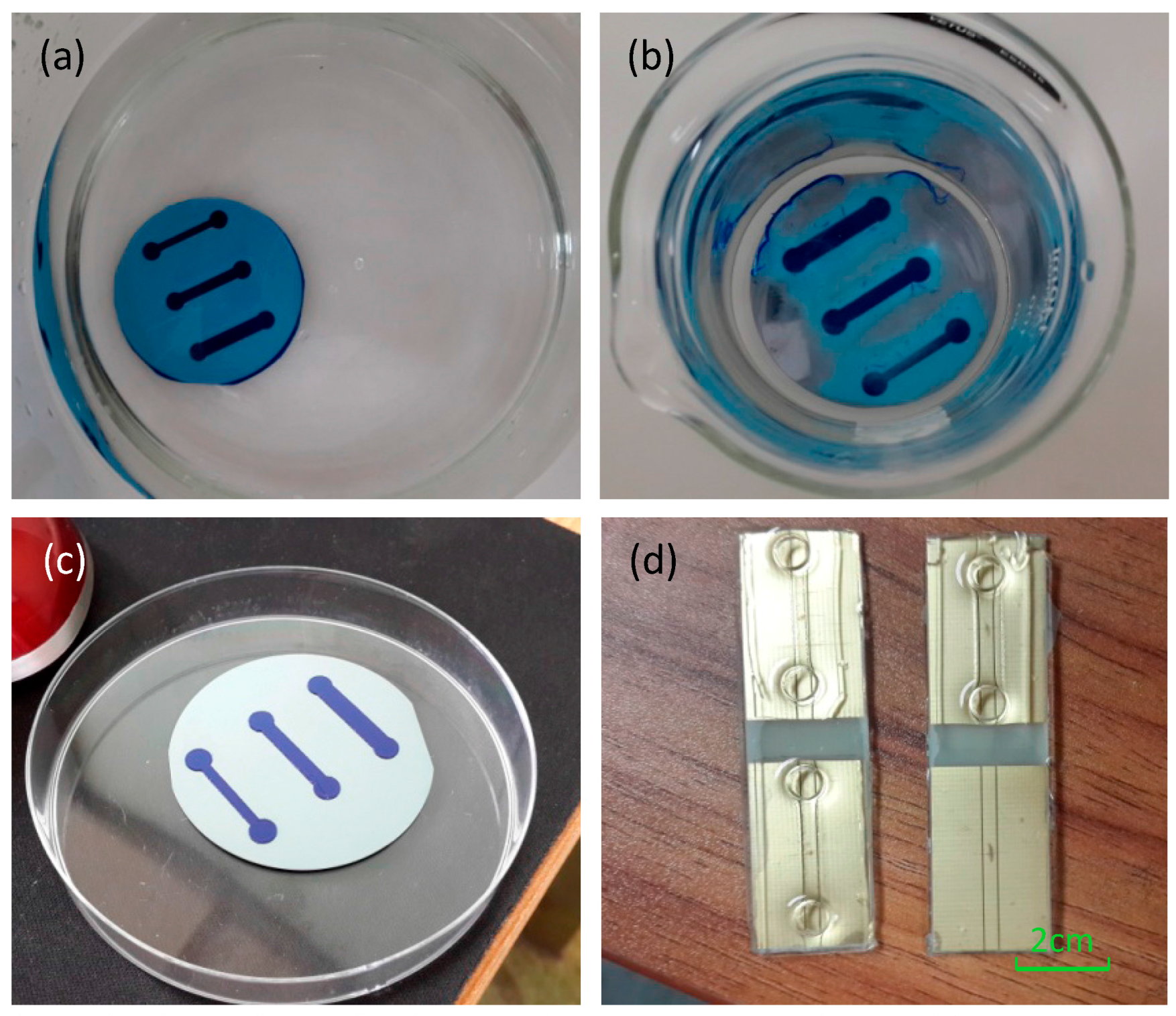
The micro-fluidic channel is fabricated using soft-lithography processes and consists of the channel with a length of 2 cm, a height of 300 μm and a width between 2 mm to 6 mm. Three different channel widths are designed in order to compare the results due to different conditions (flow rate, pressure, etc.). The ratio of the PDMS (polydimethylsiloxane) and the hardener mixture is different between the upper layer (1:10) and the protection layer (1:5) in order to make a more stable combination. The procession to fabricate the micro-channel is shown in
Figure 2.
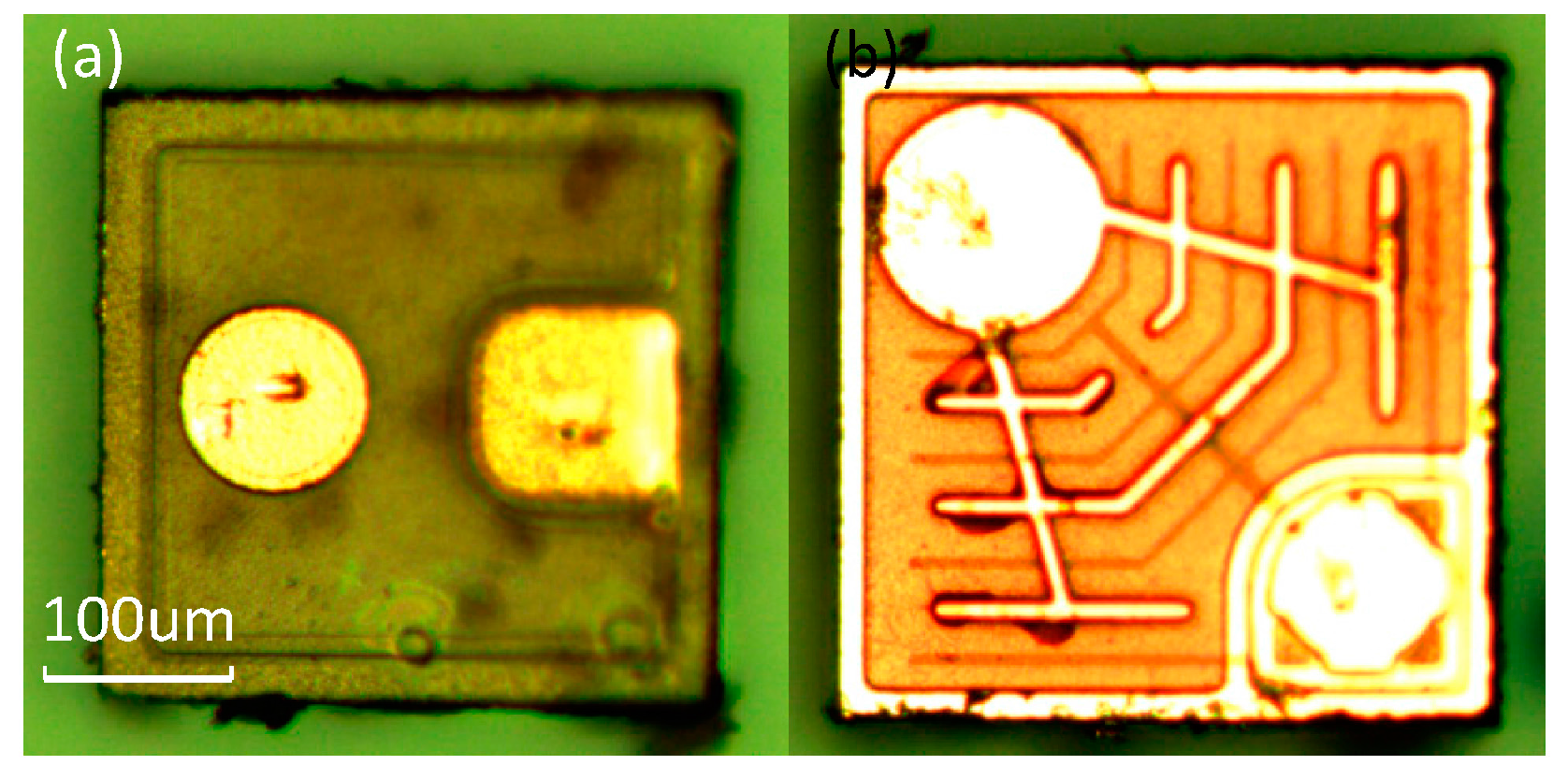
In the experiment, the red and blue on-chip light sources are used in order to match the sandwich structure of the micro-fluidic channel. Both of the light sources are on the order of microns and the emission wavelength range of the red light (ES-LAHRPH14) is 619–625 nm, and that of the blue light (ES-CEBLM12) is 462.5–465 nm. The narrow wavelength range can not only reduce the interference from light sources but can also inhibit the deviation of Beer-Lambert’s law. Besides, the voltage-stabilizing circuit was fabricated to reduce the disturbance due to the input voltage.
The bar has been marked on the images. Both light sources were attached onto the PCB (Printed Circuit Board) and wire-bonded to sputtered Au electrodes. Subsequently, the assembly was covered with a thin layer of PDMS to protect the surface of the chip and the bonding wires.
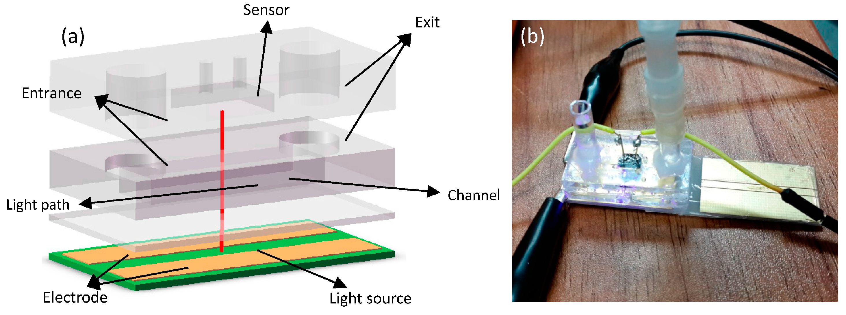
We fabricate the structure to stabilize the sensor (s1087-01, HAMAMATSU Co., Hamamatsu, Japan) and enhance the sensitivity to some specific wavelengths of light by filtering the transmitted light. The On-chip light sources and structure of sensor are shown in
Figure 3 and
Figure 4 respectively.
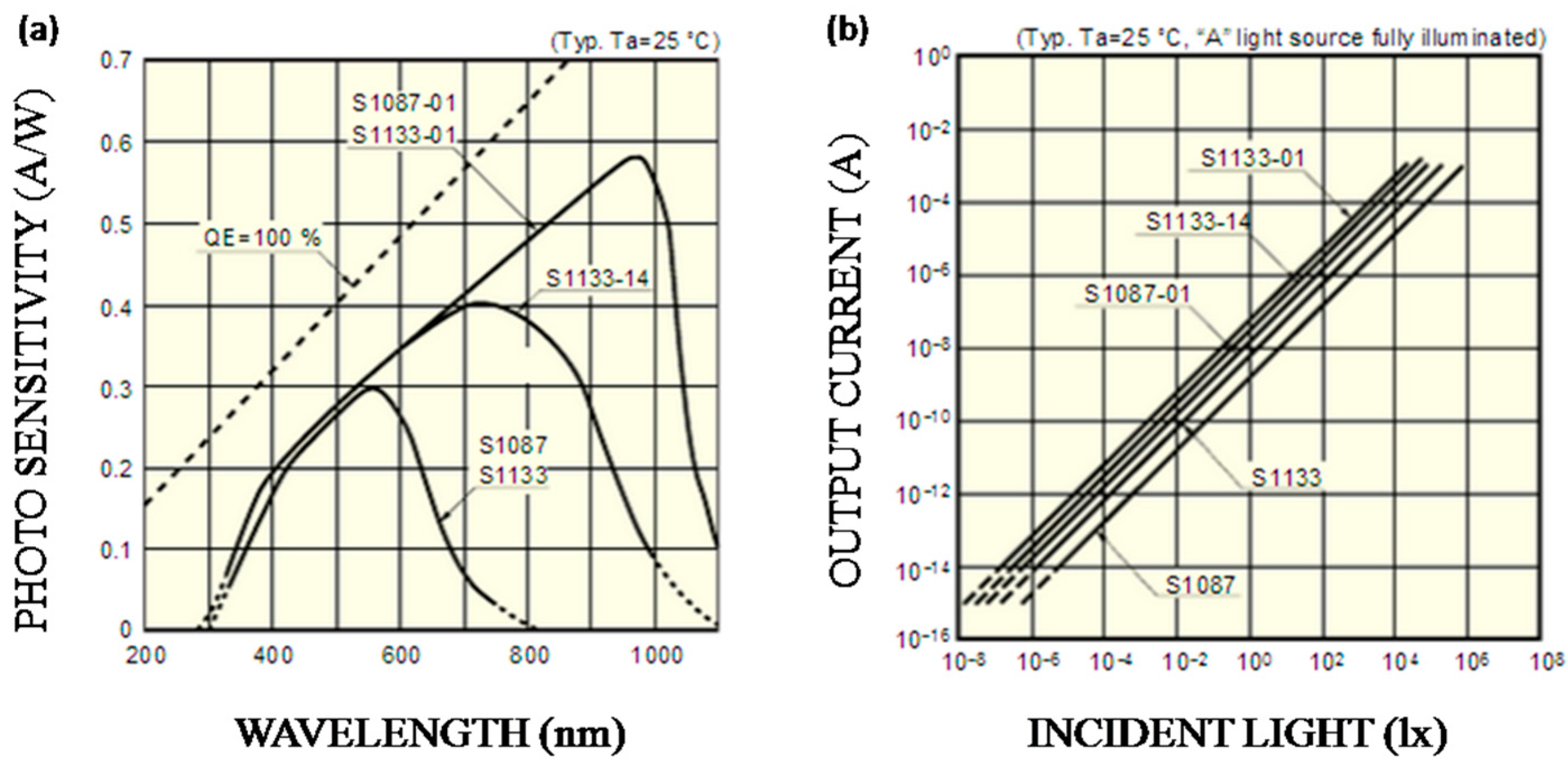
In this work, due to red light (619–625 nm) and blue light (462.5–465 nm) being selected as the light sources, S1087-01 has better photo-sensitivity than others, as
Figure 5a shows. Besides, it also has a smaller volume compared to S1133-01. As
Figure 5b shows, the output current of S1087-01 has a good linear relationship with the incident light intensity. Therefore, current signals have linear changes when transmitted light intensity changes; that is, electrical signals can represent the light intensity.
2.2.2. Processing Circuit
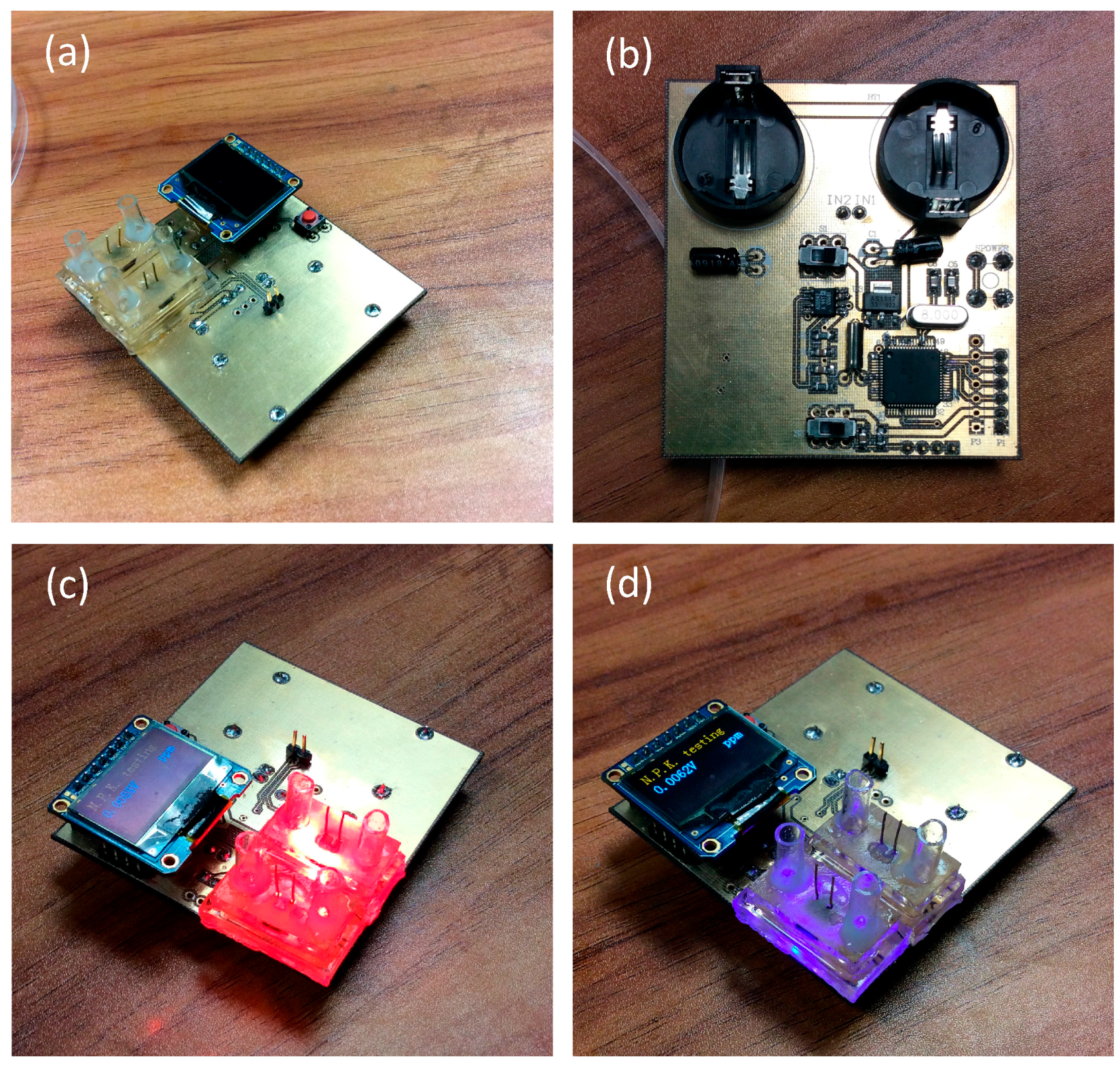
The circuit consists of a power supply, an amplifier, a filter, a MCU (Microcontroller Unit), a displayer or a wireless transmitter. All these parts were fabricated on one chip. The code written in the MCU can be easily modified to fit more complex situations, and a mini-LED was used in this experiment to show the concentration of the solutions directly. The colorimeter circuit is shown in
Figure 6.
The micro-system consists of the micro-fluidic channel, the photoelectric sensor, the signal processing module and the displayer or wireless transmission module. Photoelectric sensors (s1087-01) convert the light intensity to current signals, which is when the light intensity changes, which is caused by the changes of the solution concentrations, the current signals also change. Then, the electrical signals are amplified and filtered. Further, the MCU (F430, TI) deals with these measured signals and displays the results on the mini-LED displayer. The whole circuit can be scaled down using IC (Integrated Circuit) technology, however at an increased overall cost for low volumes.
3. Sample Solution Preparation
Ammonium nitrogen preparation: we prepared our sample solutions by using standard solutions (SS); DI water (50 mL) represents 0 ppm and the standard solution (20 ppm) consists of 100 ppm ammonium nitrogen (10 mL) and KCl (40 mL). Other test solutions are prepared by diluting standard solution, as
Table 1 shows. The chromogenic agent consists of phenol solution (50 mL) and NaClO (100 mL).
Available phosphorus preparation: standard solution consists of available phosphorus solution (10 mL, 100 ppm) and NaHCO
3 (40 mL), and the chromogenic agent is Mo-Sb-Vc. Other test solutions are prepared as
Table 1 shows.
Available potassium preparation: standard solution is a mixture of 100 ppm available potassium solution (10 mL) and NaNO
3 (40 mL), and the chromogenic agent is a mixture of EDTA-2Na, formaldehyde and thymolphthalein. Other test solutions are prepared as
Table 1 shows.
When we tested the anti-interference capability of the sensor, the standard samples were prepared by extracting a certain quality of real soil samples, and half of the real soil samples were extracted and worked as the tested samples.
4. Test Platform
The test platform consists of a micro-fluid pump (BT100-2J/YZ1515, Green Co., Beijing, China) and our colorimeter. The micro-fluid pump can control both fluid velocity and flow directions, and the flow range is from 0.002 mL/min to 380 mL/min. In our experiment, we set the revolving speed as 30 rpm to avoid the inertial focus phenomenon.
In our experiment, commercial equipment (TFC-ZNS) was chosen to make the control experiment, which was widely used in many detection areas. We prepared the solution samples and tested them. The results are shown in
Figure 7 and
Figure 8.
5. Result and Discussion
5.1. Control Experiments
In this experiment, we compare our detection results with the commercial ones to show the performance of our detector.
As shown in
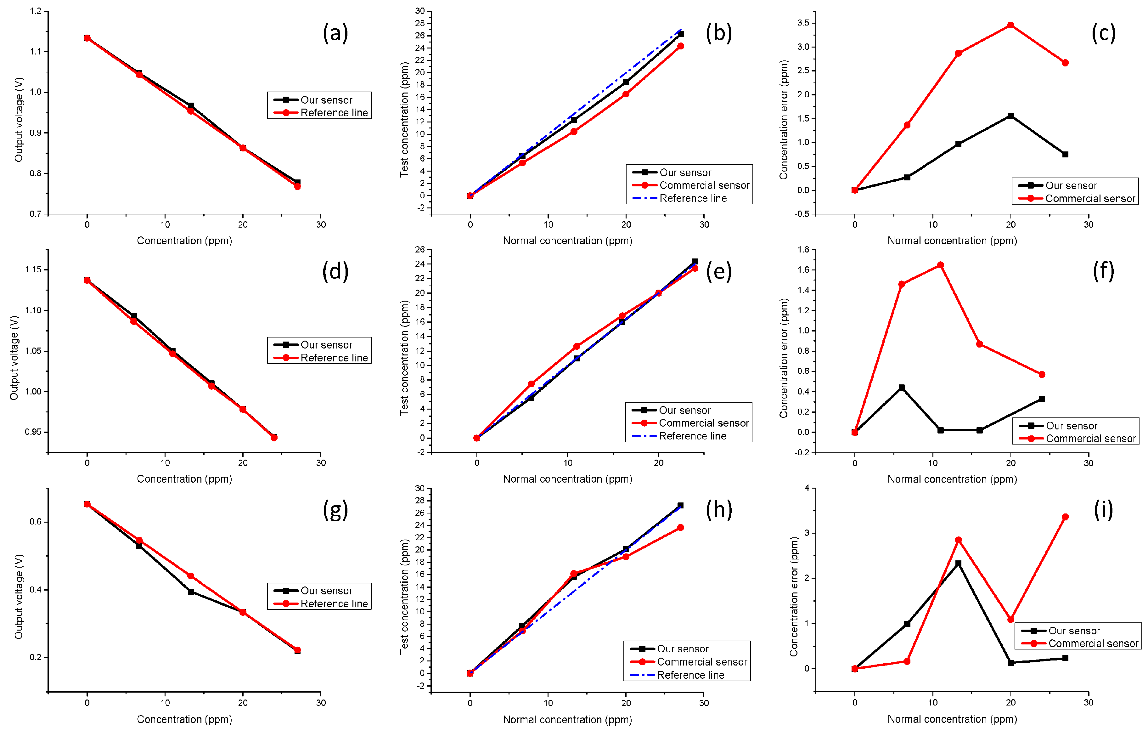
Table 1, both the DI water and standard solution (SS) are calibration solutions, and sample solutions 1 to 4 have different concentrations and a linear relationship. All the results are measured and recorded in a dark environment. As
Figure 7a,d,g show, as the NPK solution concentration increases, the transmitted light intensity becomes smaller, and the voltage signals will also decrease. Furthermore, the output voltage drops and the solution concentration has a good linear relationship for our sensor. The comparison results are shown in
Figure 7b,e,h. The better performance of our sensor in terms of error control is demonstrated in
Figure 7c,f,i, and the error between the test data of our sensor and the standard concentration is always smaller than that of the commercial equipment. In this experiment, due to 20 ppm standard solutions being used to calibrate concentration, our sensor shows better linearity with the concentration of the sample solutions as compared to the commercial one when testing solution 4 which is beyond the calibration range. Besides, the detection limits of our sensor are 83.6 ppm for N, 143 ppm for P, 40.9 and ppm for K, respectively.
5.2. Anti-Interference Capability of the System
As the sensor is based on an optical mechanism, it always has interference from ambient light; thus, a control experiment was designed to test the anti-interference capability of the system.
In this experiment, we chose soil samples from a flowerbed near our laboratory and prepared the soil solution and extracted the P elements; the detailed preparation of solutions has already been mentioned above. If we set the concentration of the standard solutions as 100%, the concentration of the soil solution should be 50%. The measurement results are shown in
Figure 8. In the dark environment, our sensor gets measurement results with a smaller error (1.5%) as compared to the commercial one (3.5%). In the normal light environment, due to the interference of ambient light, greater light intensity is received by the photoelectric sensor, and the output voltage becomes lower, and the concentration which is calculated by the MCU becomes smaller. The error of our sensor is 2.5% and it is 3.5% for the commercial equipment.
During the design and experiment, there were some methods that were found to optimize the performance of the device; for example, in order to further reduce the size of the sensor or get higher sensitivity at the same size, we can optimize the path of light. We also can optimize the processing circuit by using micro-fabricated chip technology to reduce the interference and enhance SNR.
6. Conclusions
In this paper, a novel, portable chip-level colorimeter was fabricated to detect soil nutrients based on Beer-Lambert’s law and MEMS technology. This device exhibits a good performance in terms of error control, anti-interference capability, and linearity between output voltages and concentrations. Furthermore, the sensor performs better than commercial detectors and exhibits linearity beyond the concentration of the standard solution. The device is compact and much smaller than other colorimeters, with the whole system measuring only 6 cm × 4 cm × 6 cm. Therefore, this device can be used in soil geological exploration, experimental field detection and it can even work as a sensing node to build a monitoring network.
As the detector is based on Beer-Lambert’s law, it has a wide range of uses in many other fields. Some other mixture solutions which have high absorption rates to blue light or red light can also be detected based on the same structure, and only prepared calibration solutions and modified codes are needed. It is possible to exchange the light source to detect a larger variety of substances, e.g., by using an infrared light source, the concentration of CO2 can be detected and measured.
Acknowledgments
This work was supported by the National Natural Science Foundation of China (61574083, 61434001), the National Basic Research Program of China (973 Program, 2015CB352100), the National Key Project of Science and Technology (2011ZX02403-002), and the Special Fund for Agro-scientific Research in the Public Interest (201303107) of China.
Author Contributions
Rui-Tao Liu, Lu-Qi Tao conceived the idea and designed the experiments. Rui-Tao Liu, Bo Liu, Xiang-Guang Tian performed the experiments. Rui-Tao Liu wrote the paper and analyzed the results. Mohammad Ali Mohammad, Yi Yang, Tian-Ling Ren revised the paper.
Conflicts of Interest
The authors declare no competing financial interests.
References
- McBratney, A.; Whelan, B.; Ancev, T.; Bouma, J. Future directions of precision agriculture. Precis. Agric. 2005, 6, 7–23. [Google Scholar] [CrossRef]
- Bongiovanni, R.; Lowenberg-Deboer, J. Precision agriculture and sustainability. Precis. Agric. 2004, 5, 359–387. [Google Scholar] [CrossRef]
- Zhang, N.; Wang, M.; Wang, N. Precision agriculture—A worldwide overview. Comput. Electron. Agric. 2002, 36, 113–132. [Google Scholar] [CrossRef]
- Adamchuk, V.I.; Hummel, J.W.; Morgan, M.T.; Upadhyaya, S.K. On-the-go soil sensors for precision agriculture. Comput. Electron. Agric. 2004, 44, 71–91. [Google Scholar] [CrossRef]
- Lu, Y.; Gan, H.H.; Shi, Z.J.; Liu, Z.L. Soil fertility quality assessment and managing measures for urban green space in Shenzhen City. J. Soil Water Conserv. 2005, 19, 2–5. [Google Scholar]
- Lewandowski, C.M. Soil enzyme activity and its relationship with the soil fertility in Badaling Mountain Area of Beijing. J. Beijing For. Univ. 2015, 28, 7–11. [Google Scholar]
- Gewin, V.L.; Kennedy, A.C.; Veseth, R.; Miller, B.C. Soil quality changes in eastern Washington with Conservative Reserve Program (CRP) take-out. J. Soil Water Conserv. 1999, 54, 432–438. [Google Scholar]
- Doran, J.W.; Parkin, T.B. Defining and assessing soil quality. Defin. Soil Qual. Sustain. Environ. 1994, 1–21. [Google Scholar]
- Sudduth, K.A.; Kitchen, N.R.; Bollero, G.A.; Bullock, D.G.; Wiebold, W.J. Comparison of electromagnetic induction and direct sensing of soil electrical conductivity. Agron. J. 2003, 482, 472–482. [Google Scholar] [CrossRef]
- Lobsey, C.R.; Rossel, R.V.; McBratney, A.B. Proximal soil nutrient sensing using electrochemical sensors. Prox. Soil Sens. 2010, 77–88. [Google Scholar] [CrossRef]
- Adamchuk, V.I.; Lund, E.D.; Sethuramasamyraja, B.; Morgan, M.T.; Dobermann, A.; Marx, D.B. Direct measurement of soil chemical properties on-the-go using ion-selective electrodes. Comput. Electron. Agric. 2005, 48, 272–294. [Google Scholar] [CrossRef]
- Black, C.A. Soil Fertility Evaluation and Control; Lewis: Boca Raton, FL, USA, 1992. [Google Scholar]
- Lu, R.-K. Methods of Soil Agricultural Chemical Analysis; China Agriculture Scientech Press: Beijing, China, 2000. [Google Scholar]
- Lopez-Molinero, A.; Liñan, D.; Sipiera, D.; Falcon, R. Chemometric interpretation of digital image colorimetry. Application for titanium determination in plastics. Microchem. J. 2010, 96, 380–385. [Google Scholar] [CrossRef]
- Novo, P.; França Prazeres, D.M.; Chu, V.; Conde, J.P. Microspot-based ELISA in microfluidics: Chemiluminescence and colorimetry detection using integrated thin-film hydrogenated amorphous silicon photodiodes. Lab Chip 2011, 11, 4063. [Google Scholar] [CrossRef] [PubMed]
- Afshari-Jouybari, H.; Farahnaky, A. Evaluation of photoshop software potential for food colorimetry. J. Food Eng. 2011, 106, 170–175. [Google Scholar] [CrossRef]
- Chen, X.; Chen, J.; Wang, F.; Xiang, X.; Luo, M.; Ji, X.; He, Z. Determination of glucose and uric acid with bienzyme colorimetry on microfluidic paper-based analysis devices. Biosens. Bioelectron. 2012, 35, 363–368. [Google Scholar] [CrossRef] [PubMed]
- Sinfield, J.V.; Fagerman, D.; Colic, O. Evaluation of sensing technologies for on-the-go detection of macro-nutrients in cultivated soils. Comput. Electron. Agric. 2010, 70, 1–18. [Google Scholar] [CrossRef]
- Harmon, R.S.; DeLucia, F.C.; McManus, C.E.; McMillan, N.J.; Jenkins, T.F.; Walsh, M.E.; Miziolek, A. Laser-induced breakdown spectroscopy—An emerging chemical sensor technology for real-time field-portable, geochemical, mineralogical, and environmental applications. Appl. Geochem. 2006, 21, 730–747. [Google Scholar] [CrossRef]
- Bah, A.; Balasundram, S.; Husni, M. Sensor technologies for precision soil nutrient management and monitoring. Am. J. Agric. Biol. Sci. 2012, 7, 43–49. [Google Scholar]
- Sørensen, M.K.; Jensen, O.; Bakharev, O.N.; Nyord, T.; Nielsen, N.C. NPK NMR Sensor: Online monitoring of nitrogen, phosphorus, and potassium in animal slurry. Anal. Chem. 2015, 87, 6446–6450. [Google Scholar] [CrossRef] [PubMed]
- Uludag, K.; Kohl, M.; Steinbrink, J.; Obrig, H.; Villringer, A. Cross talk in the Lambert-Beer calculation for near-infrared wavelengths estimated by Monte Carlo simulations. J. Biomed. Opt. 2002, 7, 51–59. [Google Scholar] [CrossRef] [PubMed]
- Bunaciu, A.A.; Aboul-Enein, H.Y.; Fleschin, S. Application of Fourier Transform Infrared Spectrophotometry in Pharmaceutical Drugs Analysis. Appl. Spectrosc. Rev. 2010, 45, 206–219. [Google Scholar] [CrossRef]
- Chance, B.; Villringer, A. Non-invasive optical spectroscopy and imaging of human brain function. Trends Neurosci. 1997, 20, 435–442. [Google Scholar]
- Shimada, M.; Masuda, Y.; Yamada, Y.; Itoh, M.; Takahashi, M.; Yatagai, T. Explanation of human skin color by multiple linear regression analysis based on the modified Lambert-Beer law. Opt. Rev. 2000, 7, 348–352. [Google Scholar] [CrossRef]
- Phillips, V.Z.; Kim, E.; Kim, J.G. Gender-based brain lateralization using multichannel near infrared spectroscopy. In Proceedings of the 2014 International Winter Workshop on Brain-Computer Interface (BCI), Jeongsun-kun, Korea, 17–19 February 2014; pp. 1–4.
- Downing, D.T.; Stranieri, A.M. Correction for deviation from the Lambert-Beer law in the quantitation of thin-layer chromatograms by photodensitometry. J. Chromatogr. A 1980, 192, 208–211. [Google Scholar] [CrossRef]
- Hernandez, Y.; Nicolosi, V.; Lotya, M.; Blighe, F.M.; Sun, Z.; De, S.; McGovern, I.T.; Holland, B.; Byrne, M.; Gun’Ko, Y.K.; et al. High-yield production of graphene by liquid-phase exfoliation of graphite. Nat. Nano 2008, 3, 563–568. [Google Scholar] [CrossRef] [PubMed]
- Rahman, A.; Rahman, A.K. Terahertz Non-Invasive Sub-Surface Nano-Scanner; Optical Society of America (OSA): San Diego, CA, USA, 2013. [Google Scholar]
© 2016 by the authors; licensee MDPI, Basel, Switzerland. This article is an open access article distributed under the terms and conditions of the Creative Commons Attribution (CC-BY) license (http://creativecommons.org/licenses/by/4.0/).

