
Xurography as a Rapid Fabrication Alternative for Point-of-Care Devices: Assessment of Passive Micromixers


Abstract
:
1. Introduction
2. Xurography and in-Plane Micromixers for POC Devices
3. Materials and Methods
3.1. Rapid Fabrication Process
3.2. Patterning Parameter Optimization (Layer 1)
3.3. Testing Reagents and Materials for Microdevices
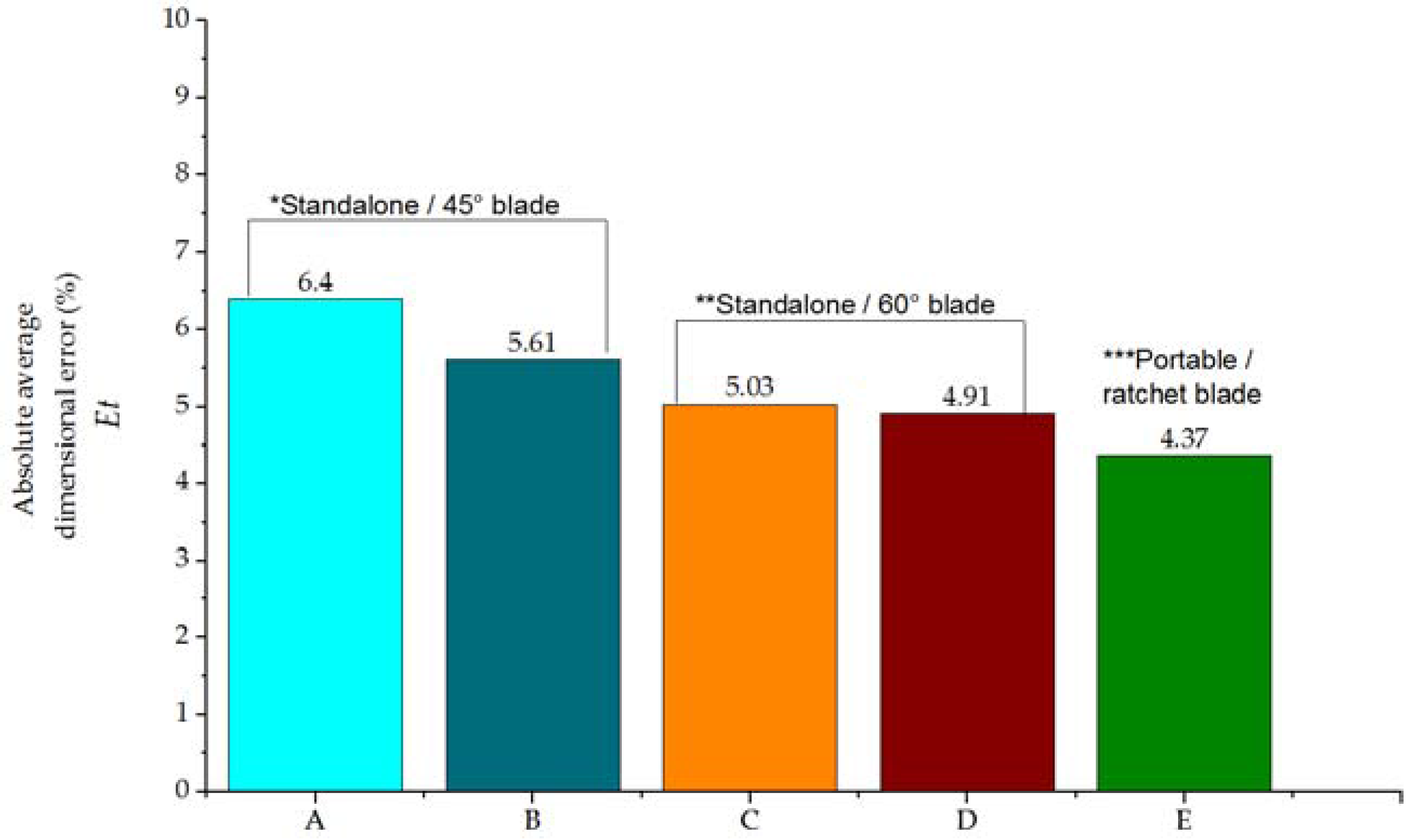
3.4. Cutting Portability Test
3.5. Proof of Concept: SAR and ASAR Passive Micromixers
3.5.1. Split and Recombine Micromixer Design and Rapid Fabrication
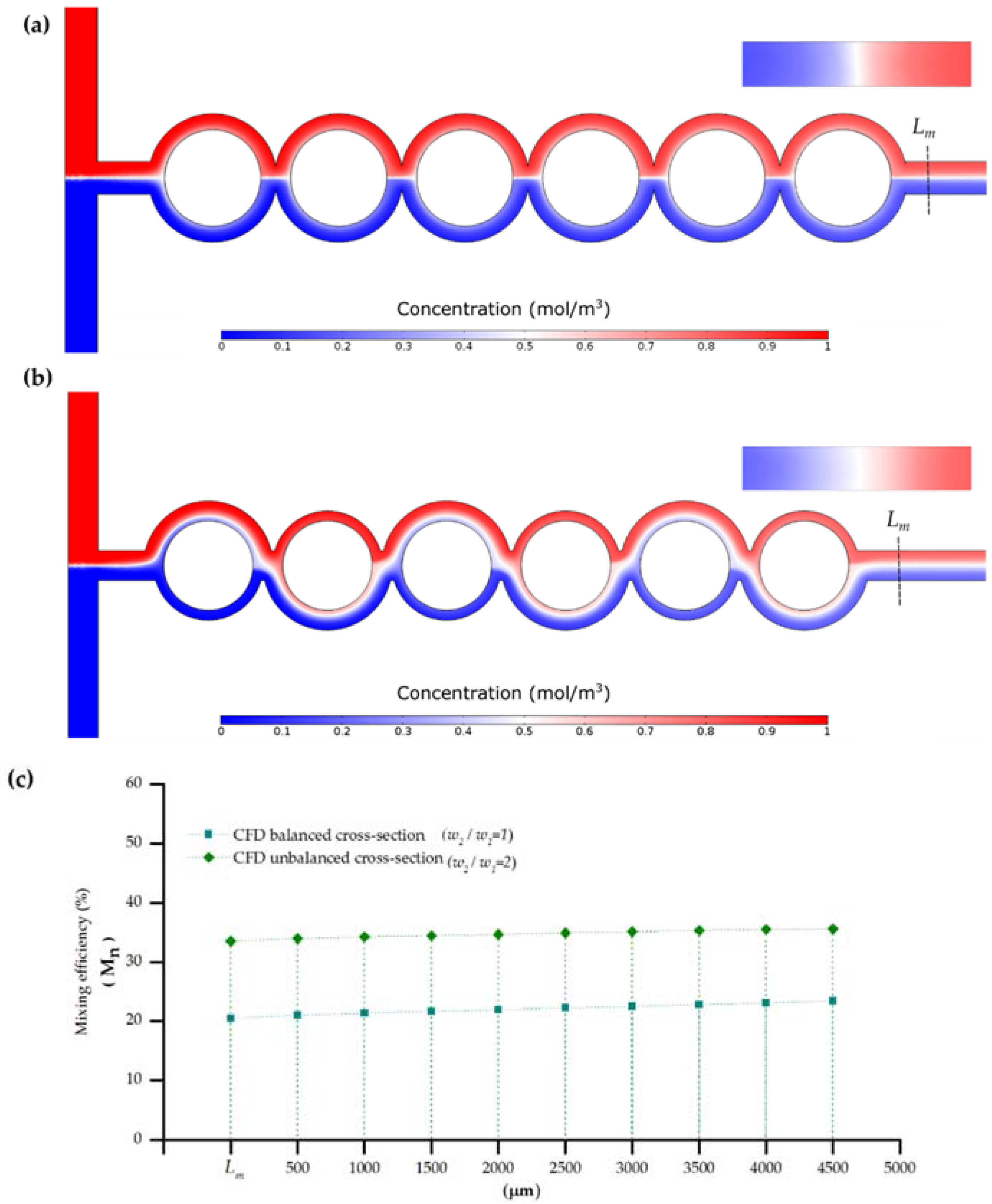
3.5.2. CFD Analysis
3.5.3. Evaluation of Experimental Micromixing Efficiency
4. Results and Discussion
4.1. Rapid Fabrication through Xurography
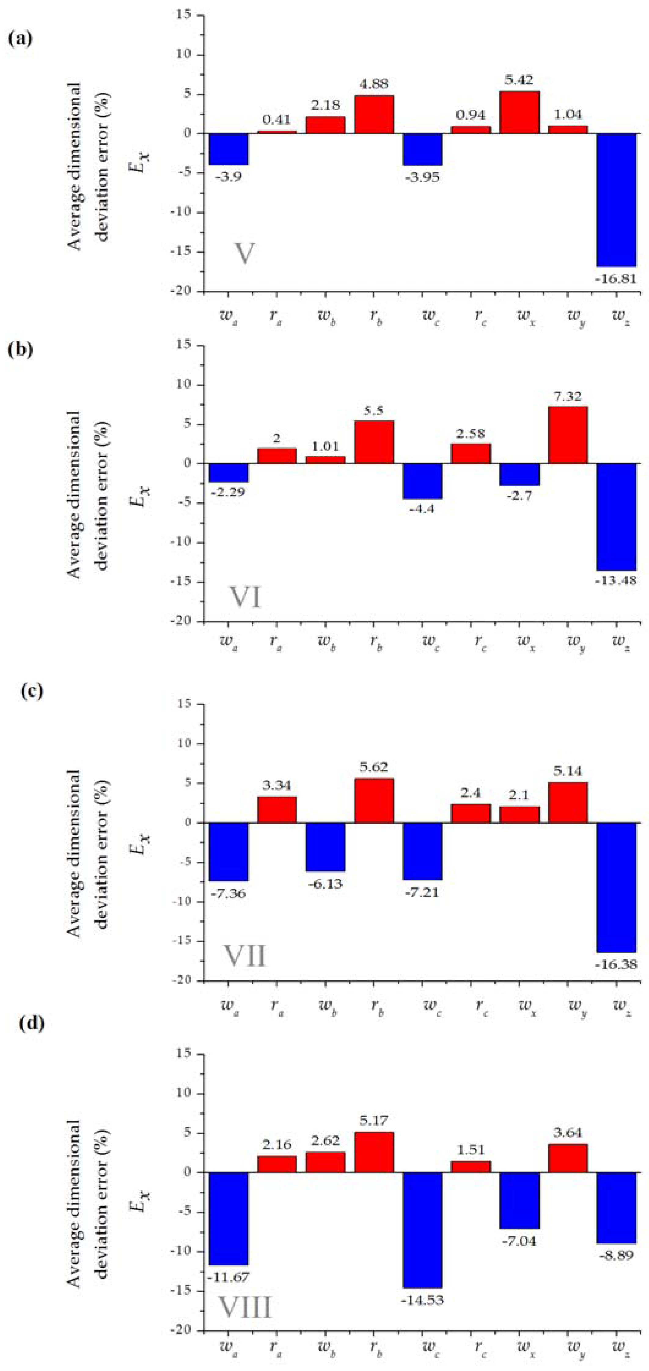
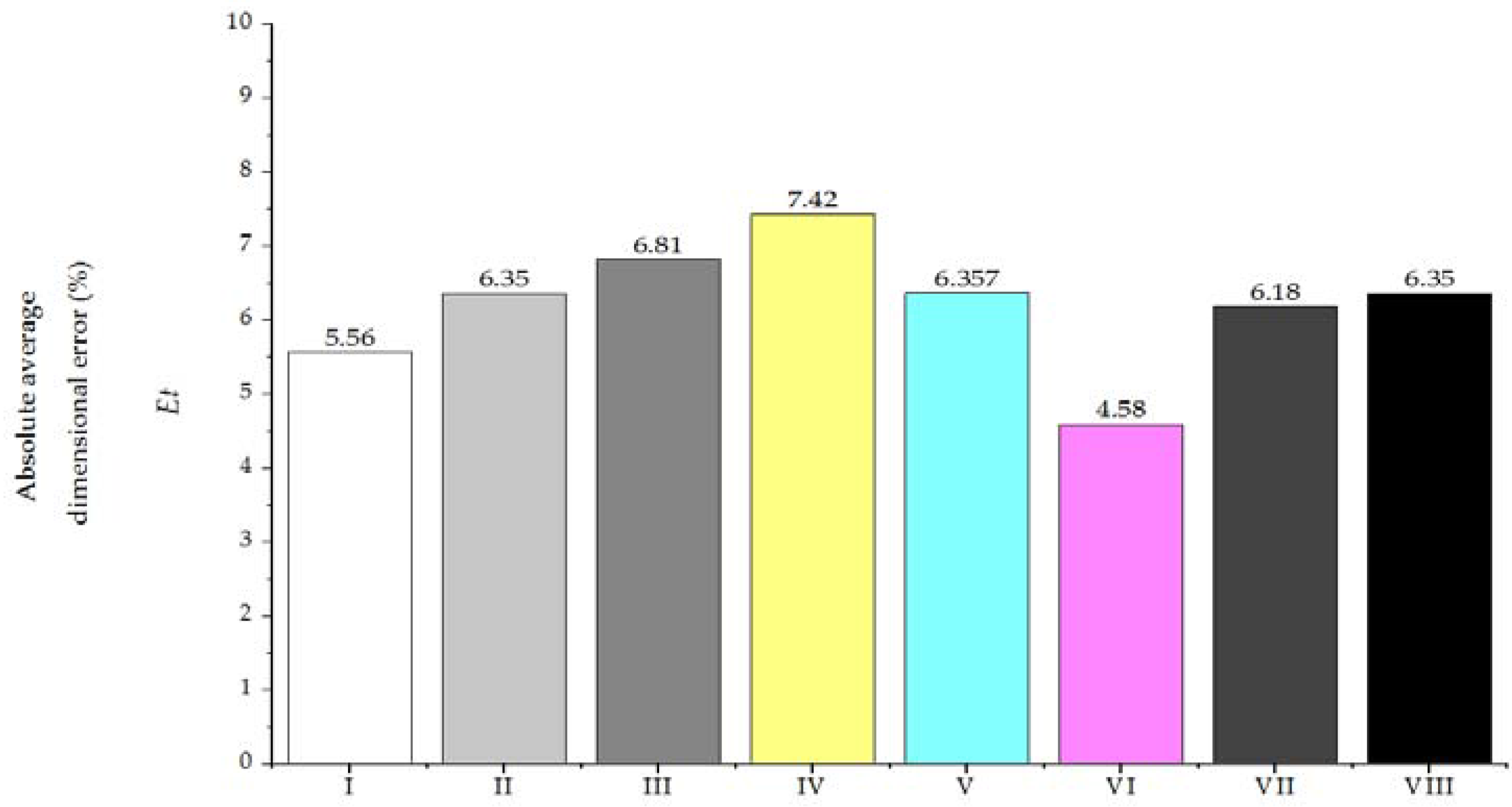
4.2. Microdevice Quality Assessment
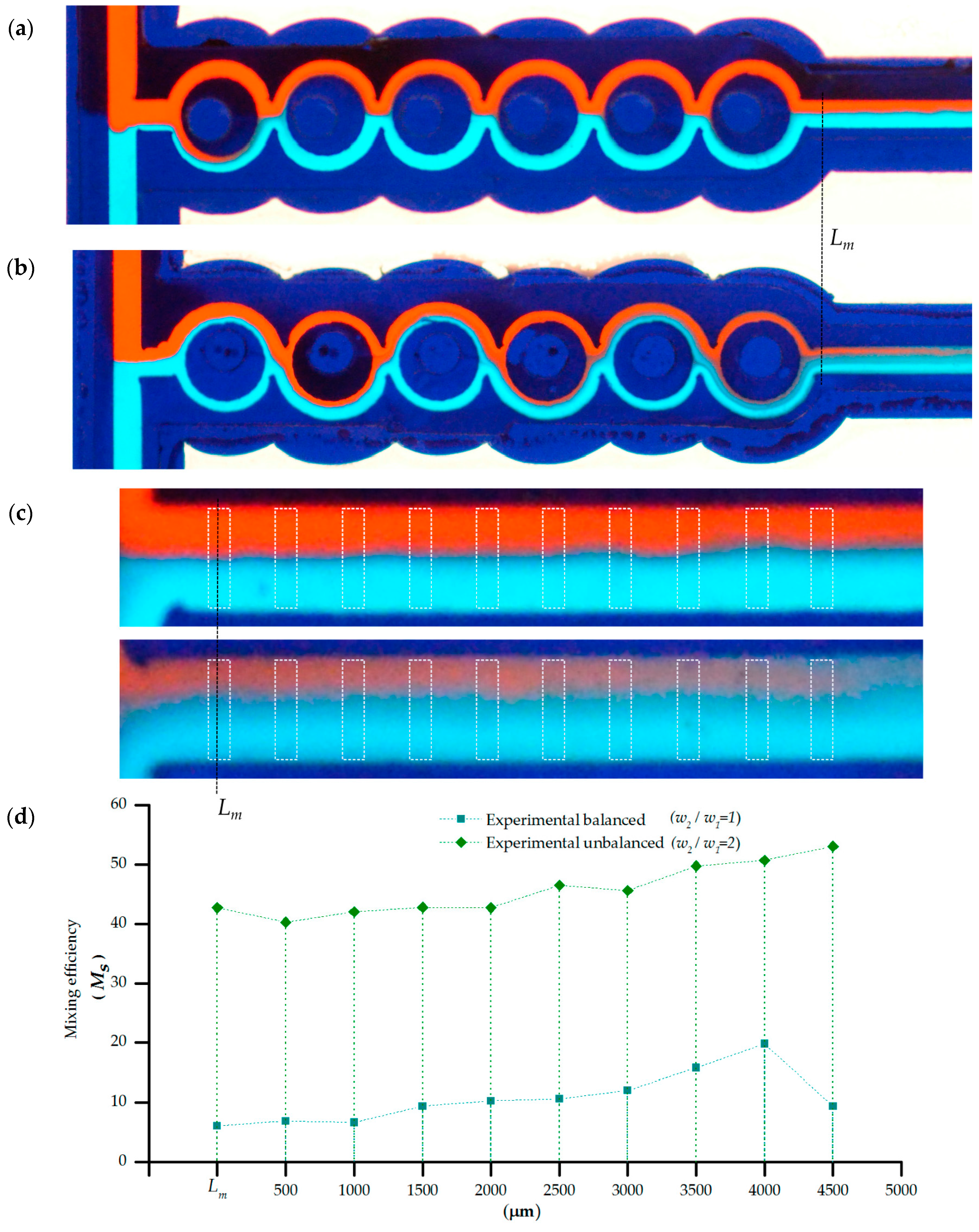
4.3. Split and Recombine Passive Micromixer
5. Conclusions and Future Work
- Xurography provides a wide range of manufacturing flexibility, without the assistance of specialized equipment or facilities.
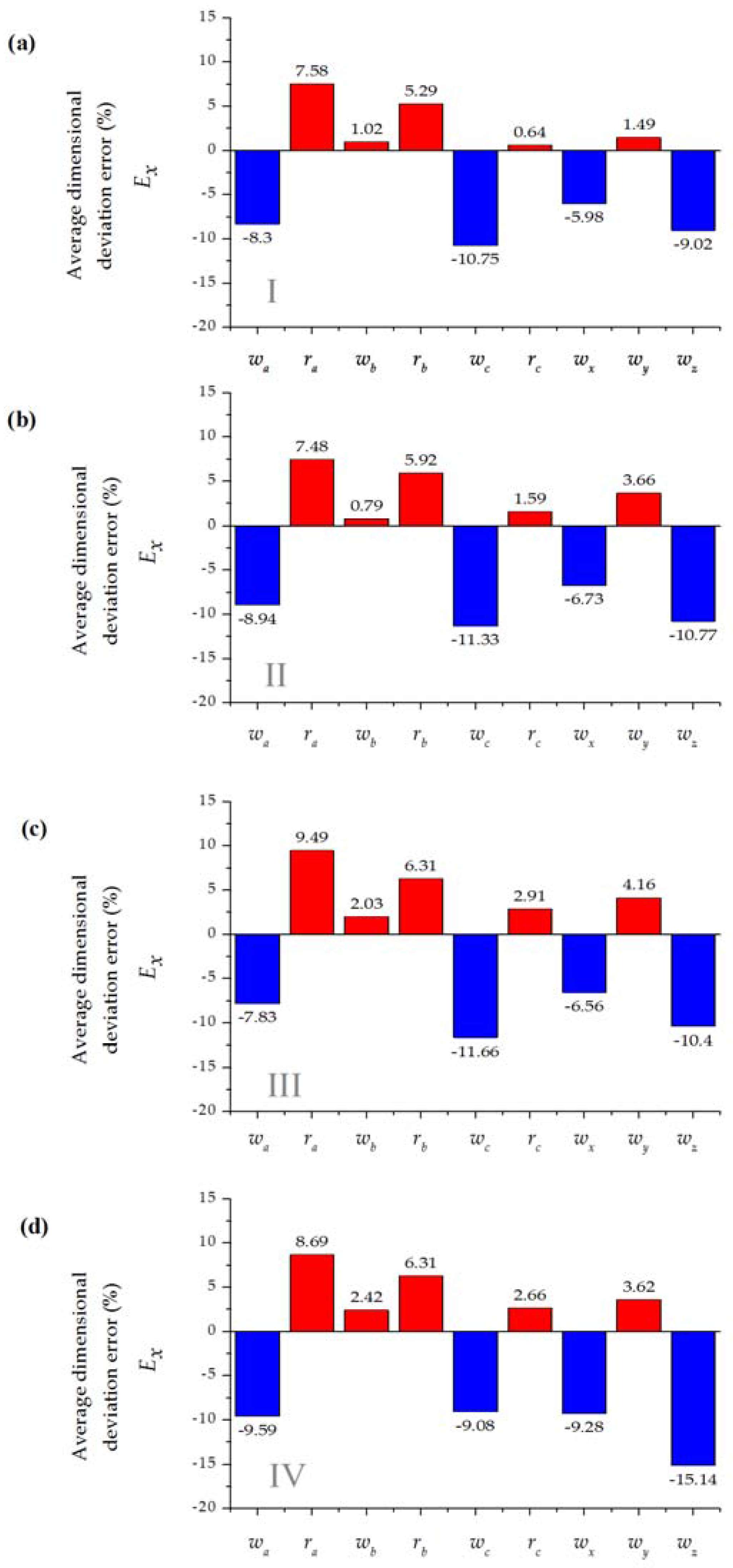
- In terms of product quality, absolute average dimensional errors below 8% can be achieved.
- The cycle time for design and manufacture of POC devices is on the order of days. For example, the study shows the manufacture of geometric feature-dependent devices (splitting and merging micromixer) in a relatively short period.
- A short cycle time, and associated cost, makes xurography suitable for disposable POC devices.
Supplementary Materials
Acknowledgments
Author Contributions
Conflicts of Interest
Abbreviations
| ASAR | Asymmetric split and recombination |
| CAD | Computer aided design |
| CFD | computational fluid dynamics |
| COC | Cyclic olefin copolymer |
| EP | electrophoresis |
| SAR | split and recombination |
| SGM | slanted grooved mixer |
| SHM | staggered herringbone mixer |
| LOC | Lab-On-a-Chip |
| PC | polycarbonate |
| PDMS | polydimethylsiloxane |
| PEEK | polyether ether ketone |
| PET | polyethylene terephthalate |
| PETG | glycol-modified polyethylene terephthalate |
| PMMA | polymethyl methacrylate |
| PETG | polyethylene terephthalate glycol |
| RGB | red-green-blue |
| PCR | polymerase chain reaction |
| POC | Point-of-Care |
| WHO | World Health Organization |
References
- Mabey, D.; Peeling, R.W.; Ustianowski, A.; Perkins, M.D. Diagnostics for the developing world. Nat. Rev. Microbiol. 2004, 2, 231–240. [Google Scholar] [CrossRef] [PubMed]
- Chin, C.D.; Linder, V.; Sia, S.K. Lab-on-a-chip devices for global health: Past studies and future opportunities. Lab Chip 2006, 7, 41–57. [Google Scholar] [CrossRef] [PubMed]
- Mogi, K.; Sugii, Y.; Yamamoto, T.; Fujii, T. Rapid fabrication technique of nano/microfluidic device with high mechanical stability utilizing two-step soft lithography. Sens. Actuators B Chem. 2014, 201, 407–412. [Google Scholar] [CrossRef]
- Natarajan, S.; Chang-Yen, D.A.; Gale, B.K. Large-area, high-aspect-ratio SU-8 molds for the fabrication of PDMS microfluidic devices. J. Micromech. Microeng. 2008, 18, 045021. [Google Scholar] [CrossRef]
- Guckenberger, D.J.; de Groot, T.E.; Wan, A.M.D.; Beebe, D.J.; Young, E.W.K. Micromilling: A method for ultra-rapid prototyping of plastic microfluidic devices. Lab Chip 2015, 15, 2364–2378. [Google Scholar] [CrossRef] [PubMed]
- Yi, X.; Kodzius, R.; Gong, X.; Xiao, K.; Wen, W. A simple method of fabricating mask-free microfluidic devices for biological analysis. Biomicrofluidics 2010, 4, 036503. [Google Scholar] [CrossRef] [PubMed]
- Bartholomeusz, D.A.; Xurography, R.W.B. Rapid prototyping of microstructures using a cutting plotter. J. Microelectromech. Syst. 2006, 14, 1364–1374. [Google Scholar] [CrossRef]
- Treise, I.; Fortner, N.; Shapiro, B.; Hightower, A. Efficient energy based modeling and experimental validation of liquid filling in planar micro-fluidic components and networks. Lab Chip 2005, 5, 285–297. [Google Scholar] [CrossRef] [PubMed]
- Weigl, B.H.; Bardell, R.; Schulte, T.; Battrell, F.; Hayenga, J. Design and Rapid Prototyping of Thin-Film Laminate-Based Microfluidic Devices. Biomed. Microdevices 2001, 3, 267–274. [Google Scholar] [CrossRef]
- Lucio do Lago, C.; Torres da Silva, H.D.; Neves, C.A.; Alves Brito-Neto, J.G.; Fracassi da Silva, J.A. A Dry Process for Production of Microfluidic Devices Based on the Lamination of Laser-Printed Polyester Films. Anal. Chem. 2003, 75, 3853–3858. [Google Scholar] [CrossRef]
- Greer, J.; Sundberg, S.O.; Wittwer, C.T.; Gale, B.K. Comparison of glass etching to xurography prototyping of microfluidic channels for DNA melting analysis. J. Micromech. Microeng. 2007, 17, 2407–2413. [Google Scholar] [CrossRef]
- Kolekar, R.D. Fluid Flow Characteristics in Xurographic Microchannels; The University of Utah: Salt Lake City, UT, USA, 2009. [Google Scholar]
- De Santana, P.P.; Segato, T.P.; Carrilho, E.; Lima, R.S.; Dossi, N.; Kamogawa, M.Y.; Gobbi, A.L.; Piazzeta, M.H.; Piccin, E. Fabrication of glass microchannels by xurography for electrophoresis applications. Analyst 2013, 138, 1660–1664. [Google Scholar] [CrossRef] [PubMed]
- Sundberg, S.O.; Wittwer, C.T.; Gao, C.; Gale, B.K. Spinning Disk Platform for Microfluidic Digital Polymerase Chain Reaction. Anal. Chem. 2010, 82, 1546–1550. [Google Scholar] [CrossRef] [PubMed]
- Kim, J.; Shin, Y.; Song, S.; Lee, J.; Kim, J. Rapid prototyping of multifunctional microfluidic cartridges for electrochemical biosensing platforms. Sens. Actuators B Chem. 2014, 202, 60–66. [Google Scholar] [CrossRef]
- Haeberle, S.; Zengerle, R. Microfluidic platforms for lab-on-a-chip applications. Lab Chip 2007, 7, 1094–1110. [Google Scholar] [CrossRef] [PubMed]
- Chin, C.D.; Linder, V.; Sia, S.K. Commercialization of microfluidic point-of-care diagnostic devices. Lab Chip 2012, 12, 2118–2134. [Google Scholar] [CrossRef] [PubMed]
- Kovarik, M.L.; Gach, P.C.; Ornoff, D.M.; Wang, Y.; Balowski, J.; Farrag, L.; Allbritton, N.L. Micro Total Analysis Systems for Cell Biology and Biochemical Assays. Anal. Chem. 2012, 84, 516–540. [Google Scholar] [CrossRef] [PubMed]
- Su, Y.; Chen, G.; Yuan, Q. Ideal micromixing performance in packed microchannels. Chem. Eng. Sci. 2011, 66, 2912–2919. [Google Scholar] [CrossRef]
- Nguyen, N.-T.; Wu, Z. Micromixers—A review. J. Micromech. Microeng. 2005, 15, R1–R16. [Google Scholar] [CrossRef]
- Schönfeld, F.; Hardt, S. Simulation of helical flows in microchannels. AIChE J. 2004, 50, 771–778. [Google Scholar] [CrossRef]
- Du, Y.; Zhang, Z.; Yim, C.; Lin, M.; Cao, X. Evaluation of Floor-grooved Micromixers using Concentration-channel Length Profiles. Micromachines 2010, 1, 19–33. [Google Scholar] [CrossRef]
- Stroock, A.D.; Dertinger, S.K.W.; Ajdari, A.; Mezić, I.; Stone, H.A.; Whitesides, G.M. Chaotic Mixer for Microchannels. Science 2002, 295, 647–651. [Google Scholar] [CrossRef] [PubMed]
- Gobby, D.; Angeli, P.; Gavriilidis, A. Mixing characteristics of T-type microfluidic mixers. J. Micromech. Microeng. 2001, 11, 126–132. [Google Scholar] [CrossRef]
- Hong, C.-C.; Choi, J.-W.; Ahn, C.H. A novel in-plane passive microfluidic mixer with modified Tesla structures. Lab Chip 2004, 4, 109–113. [Google Scholar] [CrossRef] [PubMed]
- Sudarsan, A.P.; Ugaz, V.M. Fluid mixing in planar spiral microchannels. Lab Chip 2006, 6, 74–82. [Google Scholar] [CrossRef] [PubMed]
- McDonald, J.C.; Whitesides, G.M. Poly(dimethylsiloxane) as a Material for Fabricating Microfluidic Devices. Acc. Chem. Res. 2002, 35, 491–499. [Google Scholar] [CrossRef] [PubMed]
- Ren, K.; Zhou, J.; Wu, H. Materials for Microfluidic Chip Fabrication. Acc. Chem. Res. 2013, 46, 2396–2406. [Google Scholar] [CrossRef] [PubMed]
- Chung, C.K.; Shih, T.R. Effect of geometry on fluid mixing of the rhombic micromixers. Microfluid. Nanofluidics 2007, 4, 419–425. [Google Scholar] [CrossRef]
- Chung, C.K.; Shih, T.R.; Wu, B.H.; Chang, C.K. Design and mixing efficiency of rhombic micromixer with flat angles. Microsyst. Technol. 2009, 16, 1595–1600. [Google Scholar] [CrossRef]
- Hossain, S.; Kim, K.-Y. Mixing Analysis of Passive Micromixer with Unbalanced Three-Split Rhombic Sub-Channels. Micromachines 2014, 5, 913–928. [Google Scholar] [CrossRef]
- Hong, C.-C.; Choi, J.-W.; Ahn, C.H. A Novel In-Plane Passive Micromixer Using Coanda Effect. In Micro Total Analysis Systems 2001: Proceedings of the µTAS 2001 Symposium, Held in Monterey, CA, USA 21–25 October, 2001; Ramsey, J.M., van den Berg, A., Eds.; Springer Netherlands: Dordrecht, The Netherlands, 2001; pp. 31–33. [Google Scholar]
- Hossain, S.; Ansari, M.A.; Husain, A.; Kim, K.-Y. Analysis and optimization of a micromixer with a modified Tesla structure. Chem. Eng. J. 2010, 158, 305–314. [Google Scholar] [CrossRef]
- Ansari, M.A.; Kim, K.-Y.; Anwar, K.; Kim, S.M. A novel passive micromixer based on unbalanced splits and collisions of fluid streams. J. Micromech. Microeng. 2010, 20, 055007. [Google Scholar] [CrossRef]
- Ansari, M.A.; Kim, K.-Y. Mixing performance of unbalanced split and recombine micomixers with circular and rhombic sub-channels. Chem. Eng. J. 2010, 162, 760–767. [Google Scholar] [CrossRef]
- Scherr, T.; Quitadamo, C.; Tesvich, P.; Park, D.S.-W.; Tiersch, T.; Hayes, D.; Choi, J.-W.; Nandakumar, K.; Monroe, W.T. A planar microfluidic mixer based on logarithmic spirals. J. Micromech. Microeng. 2012, 22, 055019. [Google Scholar] [CrossRef] [PubMed]
- Becker, H.; Gärtner, C. Polymer microfabrication technologies for microfluidic systems. Anal. Bioanal. Chem. 2008, 390, 89–111. [Google Scholar] [CrossRef] [PubMed]
- Martínez-López, J.I. Biosensing Enhancement of a SPR Imaging System through Micromixing Structures; Tecnologico de Monterrey: Monterrey, Mexico, 2013. [Google Scholar]
- Lynn, N.S.; Martínez-López, J.-I.; Bocková, M.; Adam, P.; Coello, V.; Siller, H.R.; Homola, J. Biosensing enhancement using passive mixing structures for microarray-based sensors. Biosens. Bioelectron. 2014, 54, 506–514. [Google Scholar] [CrossRef] [PubMed]
- Ko, Y.-J.; Maeng, J.-H.; Ahn, Y.; Hwang, S.Y. DNA ligation using a disposable microfluidic device combined with a micromixer and microchannel reactor. Sens. Actuators B Chem. 2011, 157, 735–741. [Google Scholar] [CrossRef]
- Fernández-Sempere, J.; Ruiz-Beviá, F.; Colom-Valiente, J.; Más-Pérez, F. Determination of Diffusion Coefficients of Glycols. J. Chem. Eng. Data 1996, 41, 47–48. [Google Scholar] [CrossRef]
- Wang, M.-H.; Soriano, A.N.; Caparanga, A.R.; Li, M.-H. Binary mutual diffusion coefficient of aqueous solutions of propylene glycol and dipropylene glycol. J. Taiwan Inst. Chem. Eng. 2010, 41, 279–285. [Google Scholar] [CrossRef]
- AForge.NET: Image Processing Lab. Available online: http://www.aforgenet.com/projects/iplab/ (accessed on 30 May 2016).
- ImageJ. Available online: https://imagej.nih.gov/ij/ (accessed on 7 April 2016).
- Steigert, J.; Haeberle, S.; Brenner, T.; Müller, C.; Steinert, C.P.; Koltay, P.; Gottschlich, N.; Reinecke, H.; Rühe, J.; Ducrée, J.; et al. Rapid prototyping of microfluidic chips in COC. J. Micromech. Microeng. 2007, 17, 333–341. [Google Scholar] [CrossRef]
- Carlo, D.D. Inertial microfluidics. Lab Chip 2009, 9, 3038–3046. [Google Scholar] [CrossRef] [PubMed]
- Kamholz, A.E.; Weigl, B.H.; Finlayson, B.A.; Yager, P. Quantitative Analysis of Molecular Interaction in a Microfluidic Channel: The T-Sensor. Anal. Chem. 1999, 71, 5340–5347. [Google Scholar] [CrossRef] [PubMed]


| Work (year) | * Ref | Function | Manufacture | ** Materials | Assembly |
|---|---|---|---|---|---|
| Weigl et al. (2001) | [9] | Cytometry and H-filter chambers | CO2 laser cutting, oxygen plasma treatment, lamination | PET sheets | Metal frame housing/double sided adhesive |
| Do Lago et al. (2003) | [10] | EP flow chamber/Electrospray tip | Laser printing, drilling, Gluing, Scissor cutting, lamination | Toner PET (acetate sheet) | Thermal lamination |
| Bartholomeusz (2006) | [7] | Shadow mask, PDMS micromolding, coiled channel | Xurography, lamination, Sputtering | Rubylith, Vinyl, Polyester, Aluminium, Sandblast, glass | Thermal lamination |
| Greer et al. (2007) | [11] | DNA analysis well | Xurography, drilling and heat treatment | Double sided tape, glass slides, PEEK (Nanoport) | Adhesive, thermal bonding |
| Sundberg et al. (2010) | [14] | PCR disk platform | Xurography, Thermal lamination | PETG sheets, PTFE strips | Thermal lamination |
| Santana et al. (2013) | [13] | Mask for glass etching process (EP chamber) | Xurography | Vinyl | - |
| Kim et al. (2014) | [15] | Electrochemical biosensing | Xurography, Au sputtering, CO2 laser cutting | PET, double-sided tape, PMMA, Au | Cold lamination (machine) |
| Setup | Nominal Microchannel Width wnom (μm) | Nominal Microchannel Wall Width wwall (μm) | Cutting Load fload (N) | Cutting Passes N | Material Nominal Depth dnom (μm) |
|---|---|---|---|---|---|
| I | 750 | 500 | 0.8 | 2 | 75 |
| II | 750 | 500 | 1.0 | 1 | 75 |
| III | 750 | 500 | 1.0 | 1 | 50 |
| IV | 750 | 500 | 0.8 | 2 | 50 |
| V | 200 | 500 | 0.8 | 2 | 75 |
| VI | 200 | 500 | 1.0 | 1 | 75 |
| VII | 200 | 500 | 0.8 | 2 | 50 |
| VIII | 200 | 500 | 1.0 | 2 | 50 |
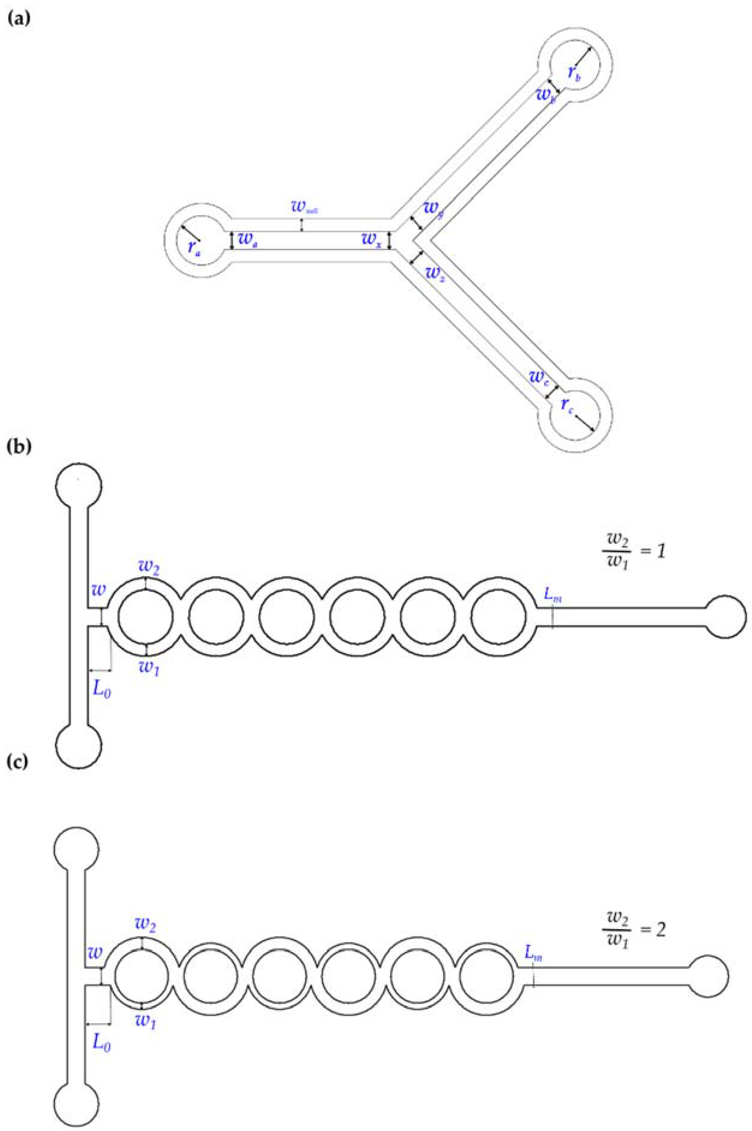
| Geometric Feature | Setups I to IV, Nominal Dimension (μm) | Setup V to VIII, Nominal Dimension (μm) |
|---|---|---|
| wa | 750 | 200 |
| ra | 1000 | 1000 |
| wb | 750 | 200 |
| rb | 1000 | 1000 |
| wc | 750 | 200 |
| rc | 1000 | 1000 |
| wx | 750 | 200 |
| wy | 750 | 200 |
| wz | 750 | 200 |
| Setup | Plotter | Blade | Patterning Parameters |
|---|---|---|---|
| A | Graphtec CE5000-60 | CB09U (45°) | fload ≈ 0.8 N, N = 1 |
| B | Graphtec CE5000-60 | CB09U (45°) | fload ≈ 0.53 N, N = 2 |
| C | Graphtec CE5000-60 | CB09UA-1 (60°) | fload ≈ 0.8 N, N = 1 |
| D | Graphtec CE5000-60 | CB09UA-1 (60°) | fload ≈ 0.6 N, N = 2 |
| E | Silhouette Portrait | Ratchet 3-3T | Blade depth = 3, material depth = 5 |
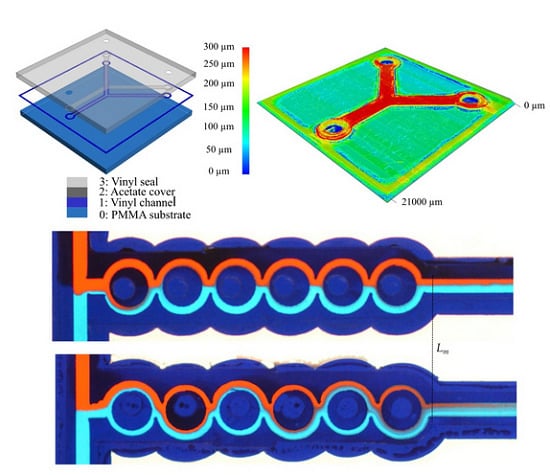
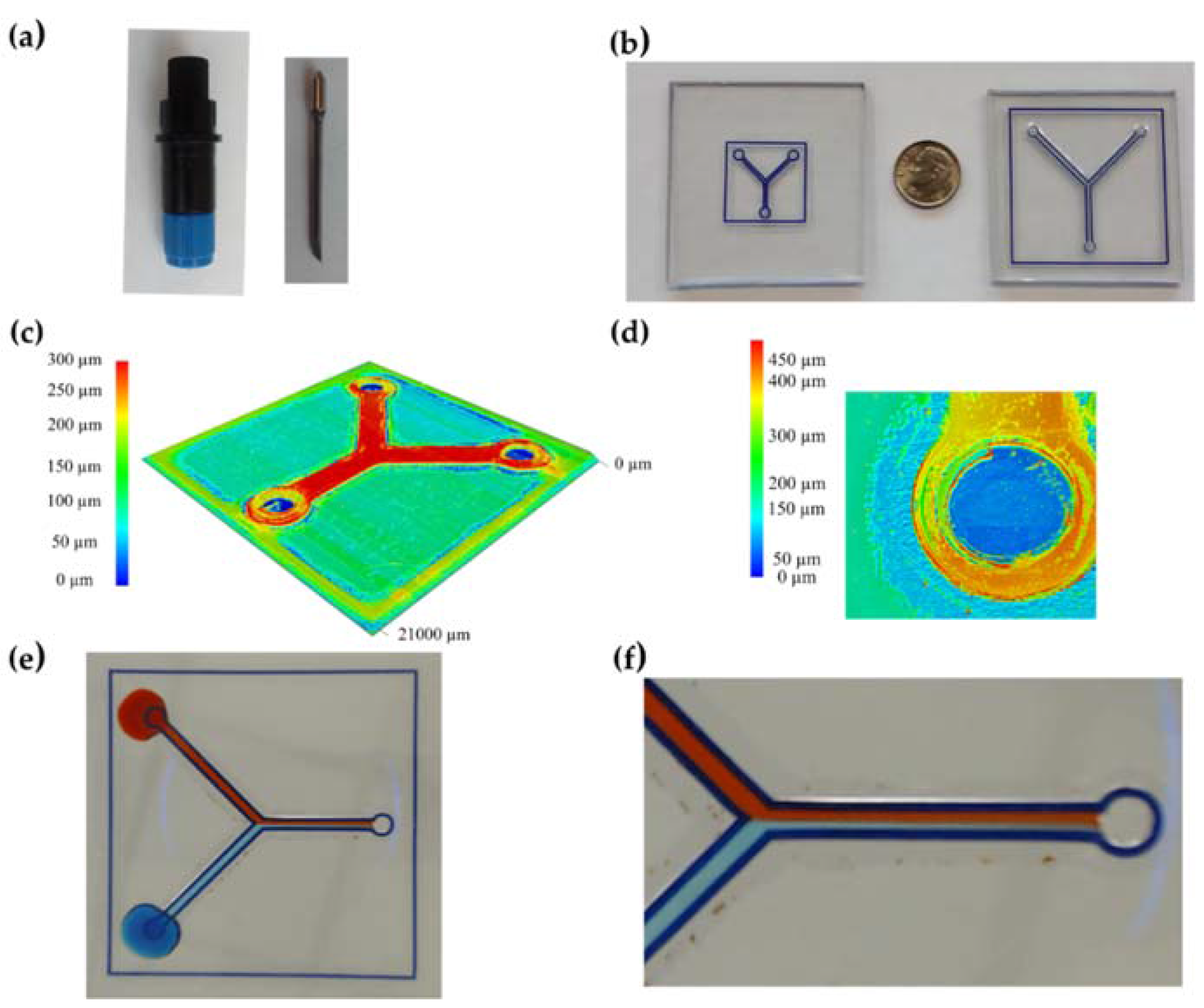
| Layer | Material | Function |
|---|---|---|
| 0 | PMMA | Substrate |
| 1 | Vinyl | Formation of flow cell walls |
| 2 | Acetate sheet | Formation of flow cell ceiling and delimitation of inlets and outlets |
| 3 | Translucent vinyl | Sealing and delimitation of inlets and outlets |
| Reference | Nominal Dimension (μm) | Compensation (μm) |
|---|---|---|
| wa | 200 | +55 |
| wc | 200 | +60 |
| wx | 200 | +55 |
| wz | 200 | +60 |
© 2016 by the authors; licensee MDPI, Basel, Switzerland. This article is an open access article distributed under the terms and conditions of the Creative Commons Attribution (CC-BY) license (http://creativecommons.org/licenses/by/4.0/).
Share and Cite
Martínez-López, J.I.; Mojica, M.; Rodríguez, C.A.; Siller, H.R. Xurography as a Rapid Fabrication Alternative for Point-of-Care Devices: Assessment of Passive Micromixers. Sensors 2016, 16, 705. https://doi.org/10.3390/s16050705
Martínez-López JI, Mojica M, Rodríguez CA, Siller HR. Xurography as a Rapid Fabrication Alternative for Point-of-Care Devices: Assessment of Passive Micromixers. Sensors. 2016; 16(5):705. https://doi.org/10.3390/s16050705
Chicago/Turabian StyleMartínez-López, J. Israel, Mauricio Mojica, Ciro A. Rodríguez, and Héctor R. Siller. 2016. "Xurography as a Rapid Fabrication Alternative for Point-of-Care Devices: Assessment of Passive Micromixers" Sensors 16, no. 5: 705. https://doi.org/10.3390/s16050705
APA StyleMartínez-López, J. I., Mojica, M., Rodríguez, C. A., & Siller, H. R. (2016). Xurography as a Rapid Fabrication Alternative for Point-of-Care Devices: Assessment of Passive Micromixers. Sensors, 16(5), 705. https://doi.org/10.3390/s16050705