Article

Joint Transmit Antenna Selection and Power Allocation for ISDF Relaying Mobile-to-Mobile Sensor Networks

1
College of Information Science and Engineering, Ocean University of China, Qingdao 266100, China
2
Department of Electrical and Computer Engineering, University of Victoria, Victoria, BC V8W 2Y2, Canada
*
Author to whom correspondence should be addressed.
Sensors 2016, 16(2), 249; https://doi.org/10.3390/s16020249
Submission received: 5 January 2016 / Revised: 2 February 2016 / Accepted: 14 February 2016 / Published: 19 February 2016
(This article belongs to the Special Issue Mobile Sensor Computing: Theory and Applications)

Abstract

:
The outage probability (OP) performance of multiple-relay incremental-selective decode-and-forward (ISDF) relaying mobile-to-mobile (M2M) sensor networks with transmit antenna selection (TAS) over N-Nakagami fading channels is investigated. Exact closed-form OP expressions for both optimal and suboptimal TAS schemes are derived. The power allocation problem is formulated to determine the optimal division of transmit power between the broadcast and relay phases. The OP performance under different conditions is evaluated via numerical simulation to verify the analysis. These results show that the optimal TAS scheme has better OP performance than the suboptimal scheme. Further, the power allocation parameter has a significant influence on the OP performance.

1. Introduction

To meet the increasing demands for high-data-rate services, mobile-to-mobile (M2M) communications has attracted significant interest from both industry and academia [1]. The M2M system architecture is described in [2]. In M2M communication systems, mobile users can directly communicate with each other without using a base station. This requires half the resources of traditional cellular communications, and thus improves the spectral efficiency and reduces the traffic load of the core network [3]. M2M communications can also be used to increase the data rate, reduce energy costs, reduce transmission delays, and extend the coverage area. Due to these advantages, M2M communications is an excellent choice for inter-vehicular communications, mobile sensor networks, and mobile heterogeneous networks [4]. M2M technologies have been proposed for home network applications [5]. In contrast to conventional fixed-to-mobile (F2M) cellular systems, both the transmitter and receiver in M2M systems can be in motion. Further, they are equipped with low elevation antennas. Thus, the widely employed Rayleigh, Rician, and Nakagami fading channels are not applicable to M2M communications systems [6]. Experimental results and theoretical analysis have shown that M2M channels can be described by cascaded fading channels [7]. The cascaded Rayleigh (also named as N-Rayleigh), fading channel was presented in [8]. The N-Rayleigh fading channel with N = 2, denoted the double-Rayleigh fading model, was considered in [9]. The N-Rayleigh fading channel was extended to the N-Nakagami fading channel in [10]. The N-Nakagami fading model with N = 2 is called the double-Nakagami fading model [11].
M2M communications may generate interference to existing cellular networks. To provide reliable cellular communications, the M2M transmit power and the distance between pairs of M2M users should be constrained. An M2M pair assisted by a relay can extend the coverage area with less transmit power. Therefore, relay-assisted M2M cooperative communications is an attractive solution to the interference problem. The pairwise error probability (PEP) of two relay-assisted vehicular scenarios using fixed-gain amplify-and-forward (FAF) relaying over double-Nakagami fading channels has been obtained [12]. An approximation for the average symbol error probability (SEP) has been derived for multiple-mobile-relay-based FAF relaying M2M cooperative networks over N-Nakagami fading channels [13]. Using the moment-generating function (MGF) approach, exact average SEP expressions for an AF M2M system over N-Nakagami fading channels have been derived [14].
Because of their low complexity, selective relaying (SR) and incremental relaying (IR) are widely employed in cooperative networks. Closed-form expressions for the error probability of incremental DF (IDF) and incremental AF (IAF) relaying over Rayleigh fading channels have been derived [15]. Further, an opportunistic IDF cooperation scheme employing orthogonal space-time block codes (OSTBC) over Rayleigh fading channels has been proposed [16]. In [17], closed-form OP expressions for IAF relaying M2M cooperative networks over N-Nakagami fading channels were derived. Exact average bit error probability (BEP) expressions for IDF relaying M2M cooperative networks over N-Nakagami fading channels were derived in [18].
Selective relaying (SR) cooperative networks are not efficient in terms of time and frequency resources. In IR cooperative networks, if the signal-to-noise ratio (SNR) of the link between the source and relay is low, messages may not be decoded correctly by the relay, which can cause error propagation. Considering these problems, Chen et al. [19] proposed a novel incremental-selective DF (ISDF) relaying scheme over Rayleigh fading channels which combines the IDF and SDF relaying protocols [19]. Exact closed-form OP expressions for ISDF relaying M2M cooperative networks over N-Nakagami fading channels were derived in [20].
Multiple-input-multiple-output (MIMO) transmission is a powerful technique which can be used to enhance the reliability and capacity of wireless systems. However, MIMO systems require multiple radio frequency chains, which increases the hardware complexity of the system. Transmit antenna selection (TAS) has been proposed as a practical way to reduce this complexity. In [21], the performance of optimal and suboptimal TAS schemes was investigated. Closed-form OP expressions for TAS MIMO networks over fading channels were derived in [22], and the energy efficiency was evaluated in [23].
Optimum power allocation is an important consideration in realizing the full potential of relay-assisted transmission. The resource allocation problem in both the uplink and downlink of two-tier networks comprising spectrum-sharing femtocells and macrocells has been investigated [24]. Further, the joint uplink subchannel and power allocation problem in cognitive small cells using cooperative Nash bargaining game theory was considered in [25]. A resource allocation scheme for orthogonal frequency division multiple access (OFDMA) based cognitive femtocells has been proposed [26], and secure resource allocation for OFDMA two-way relay wireless sensor networks was considered in [27].
However, to the best of our knowledge, the OP performance of ISDF relaying M2M sensor networks with TAS over N-Nakagami fading channels has not been investigated. Moreover, most results in the literature do not consider the power allocation. This is important, as it can have a significant effect on the OP performance. The main contributions of this paper are as follows:
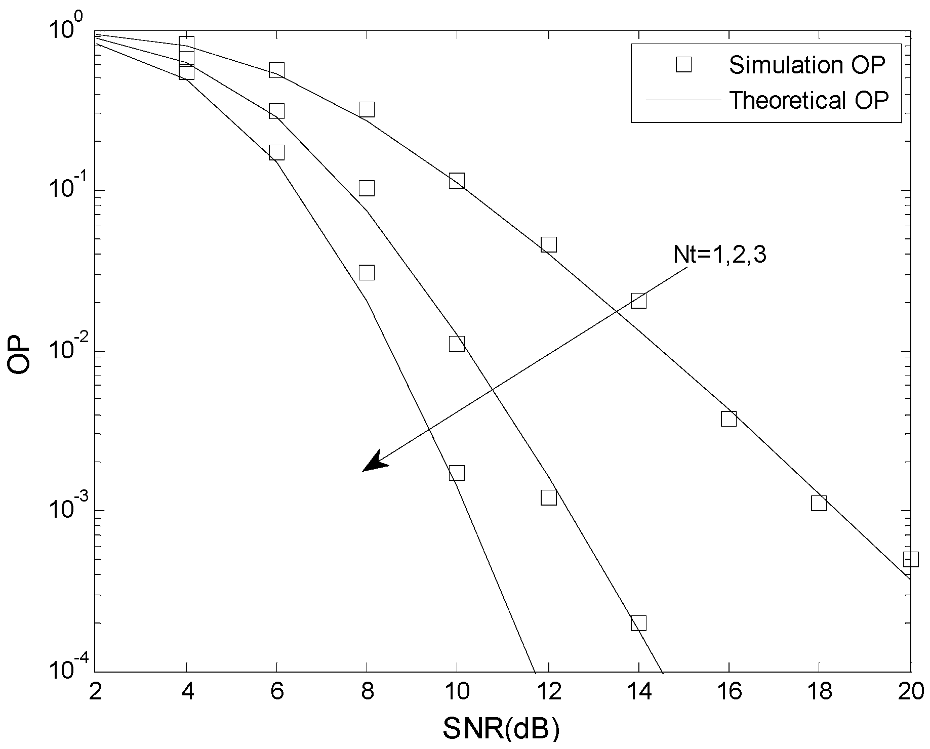
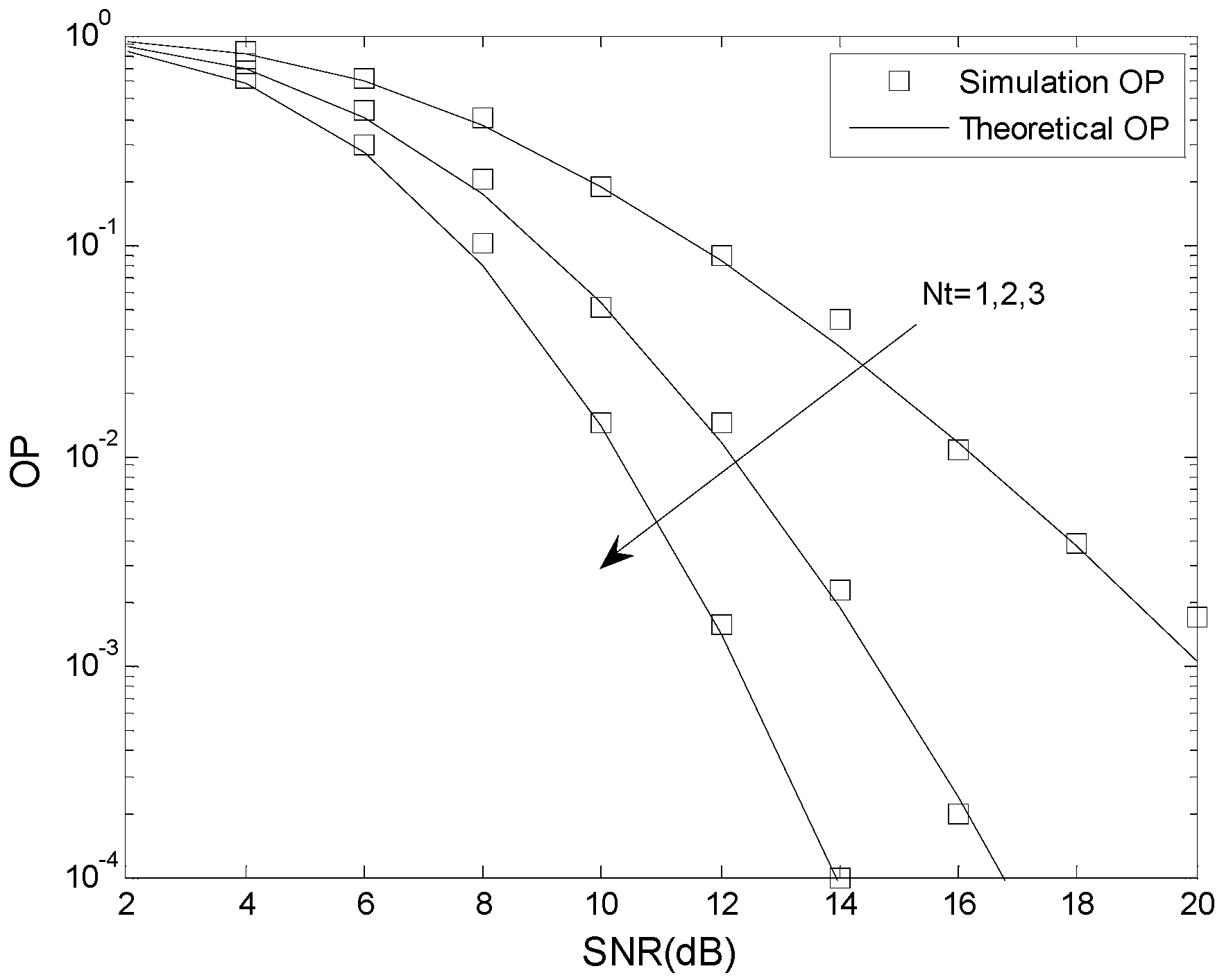
  • Closed-form expressions for the probability density function (PDF) and cumulative density functions (CDF) of the SNR over N-Nakagami fading channels are presented. These are used to derive exact closed-form OP expressions for optimal and suboptimal TAS schemes. These expressions can be used to evaluate the performance of inter-vehicular networks, mobile wireless sensor networks, and mobile heterogeneous networks.
  • The power allocation problem is formulated to determine the optimum power distribution between the broadcast and relay phases.
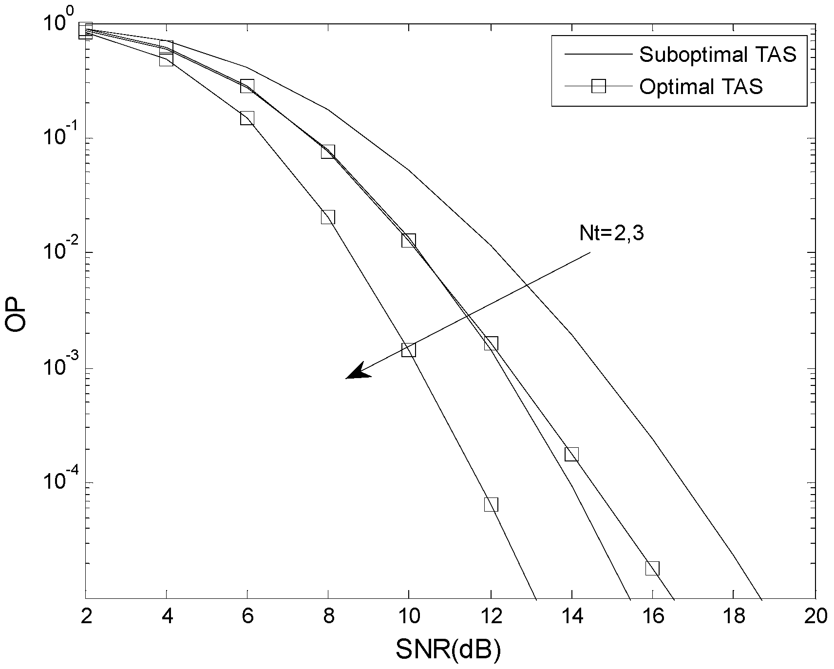
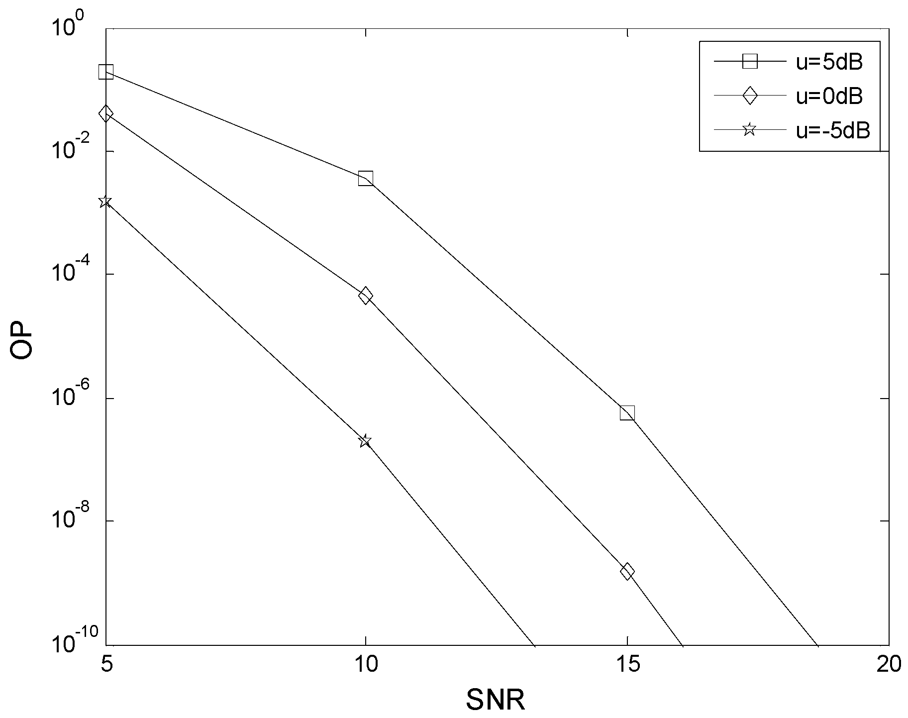
  • The accuracy of the analytical results under different conditions is verified through numerical simulation. Results are given which show that the optimal TAS scheme has better OP performance than the suboptimal scheme. It is further shown that the power allocation parameter has a significant influence on the OP performance.
  • The OP expressions presented can be used to evaluate the performance of senor communication systems employed in inter-vehicular networks, mobile wireless sensor networks and mobile heterogeneous networks.
The rest of this paper is organized as follows. The multiple-mobile-relay-based M2M sensor network model is presented in Section 2. Section 3 provides exact closed-form OP expressions for the optimal TAS scheme. Exact closed-form OP expressions for the suboptimal TAS scheme are given in Section 4. In Section 5, the OP is optimized based on the power allocation parameter. Monte Carlo simulation results are presented in Section 6 to verify the analytical results. Finally, some concluding remarks are given in Section 7.

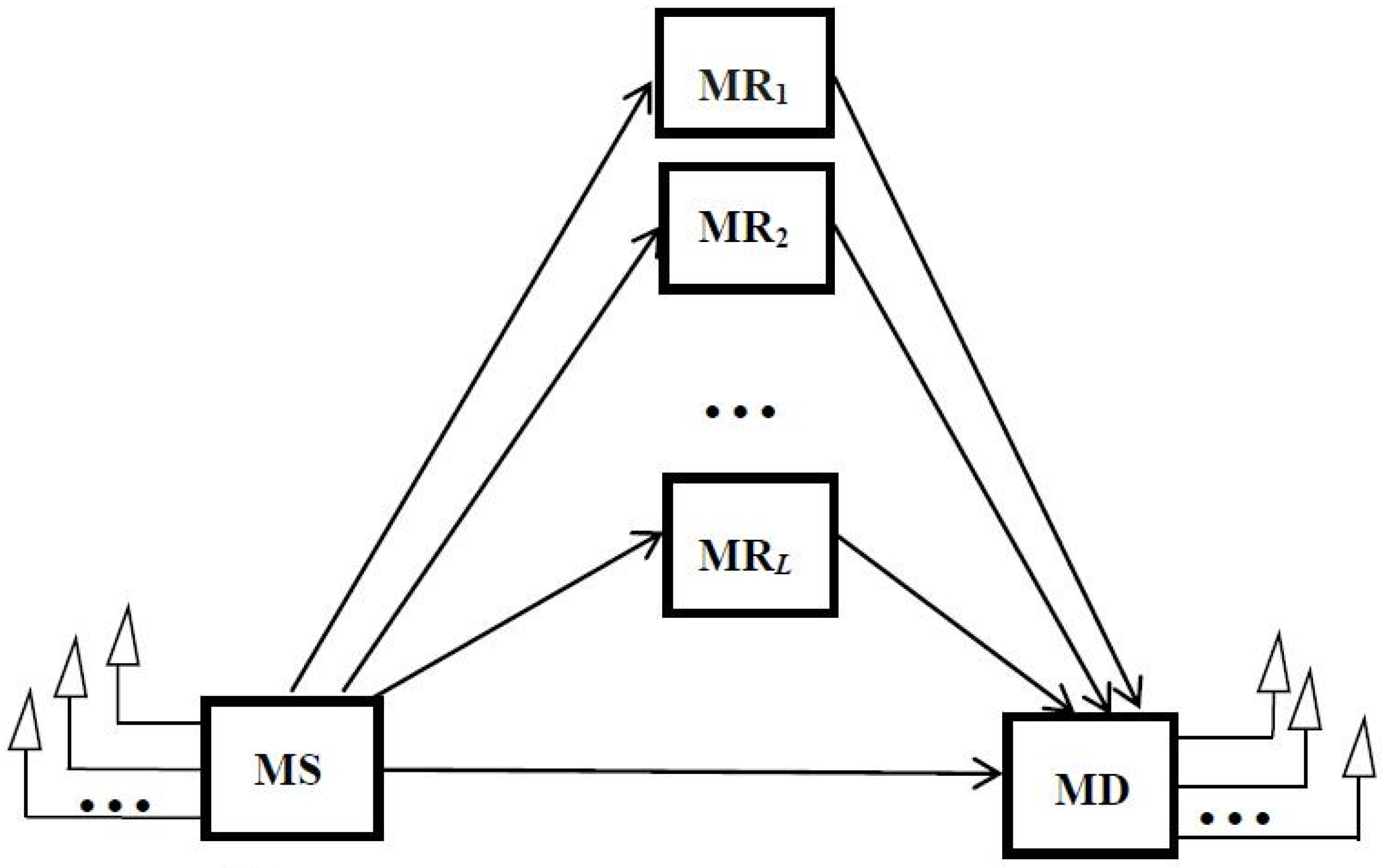
2. The System and Channel Model

2.1. System Model

The cooperation model consists of a single mobile source (MS) sensor, L mobile relay (MR) sensors, and a single mobile destination (MD) sensor, as shown in Figure 1. The nodes operate in half-duplex mode. The MS is equipped with Nt antennas, the MD is equipped with Nr antennas, and the MR is equipped with a single antenna.
It is assumed that the antennas at the MS and MD have the same distance to the relay nodes. Using the approach in [11], the relative gain of the MS to MD link is GSD = 1, the relative gain of the MS to MRl link is GSRl = (dSD/dSRl)v, and the relative gain of the MRl to MD link is GRDl = (dSD/dRDl)v, where v is the path loss coefficient, and dSD, dSRl, and dRDl are the distances of the MS to MD, MS to MRl, and MRl to MD links, respectively [28]. To indicate the location of MRl with respect to the MS and MD, the relative geometrical gain μl = GSRl/GRDl is defined. When MRl is closer to the MD, μl is less than 1, and when MRl is closer to the MS, μl is greater than 1. When MRl has the same distance to the MS and MD, μl is 1 (0 dB).
Let MSi denote the ith transmit antenna at MS and MDj denote the jth receive antenna at MD. Further, let h = hk, k∈{SDij, SRil, RDlj} represent the complex channel coefficients of the MSi to MDj, MSi to MRl, and MRl to MDj links, respectively. If the ith antenna at the MS is selected, during the first time slot the received signal rSDij at MDj is given by
r SD i j = K E h SD i j x + n SD i j
and the received signal rSRil at MRl by
r SR i l = G SR i l K E h SR i l x + n SR i l
where x denotes the transmitted symbol, and nSRil and nSDij are additive white Gaussian noise (AWGN) with zero mean and variance N0/2. During the two time slots, E is the total energy used by the MS and MR, and K is the power allocation parameter.
During the second time slot, by comparing the instantaneous SNR γSDij to a threshold γP, only the best MR decides whether to be active.
If γSDij > γP, then MSi and the best MR will receive a ‘success’ message. MSi then transmits the next message, and the best MR remains silent. The corresponding received SNR at MDj is
γ 0 i j = γ SD i j
where
γ SD i j = K | h SD i j | 2 E N 0 = K | h SD i j | 2 γ ¯
If γSDij < γP, then MSi and the best MR will receive a ‘failure’ message. By comparing the instantaneous SNR γSRi to a threshold γT, the best MR decides whether to decode and forward the signal to the MDj, where γSRi represents the SNR of the link between MSi and the best MR. The best MR is selected based on the following decision rule
γ SR i = max 1 l L ( γ SR i l )
where γSRil represents the SNR of the MSi to MRl link, and
γ SR i l = K G SR i l | h SR i l | 2 E N 0 = K G SR i l | h SR i l | 2 γ ¯
If γSri < γT, then MSi will transmit the next message, and the best MR will not be used for cooperation. The corresponding received SNR at MDj is
γ 1 i j = γ SD i j
If γSri > γT, then the best MR decodes and forwards the signal to MDj. The corresponding received signal at MDj is
r RD j = ( 1 K ) G RD j E h RD j x + n RD j
where nRDj is AWGN with zero mean and variance N0/2.
If MDj uses selection combining (SC), the received SNR is given by
γ SC i j = max ( γ SD i j , γ RD j )
where γRDj represents the SNR of the link between the best MR and MDj. Using SC at the MD, the received SNR is
γ SC i = max 1 j N r ( γ i j )
where
γ i j = { γ 0 i j , γ SD i j > γ P γ 1 i j , γ SD i j < γ P , γ SR i < γ T γ SC i j , γ SD i j < γ P , γ SR i > γ T
The optimal TAS scheme selects the transmit antenna w that maximizes the received SNR at the MD, namely
w = max 1 i N t ( γ SC i ) = max 1 i N t , 1 j N r ( γ i j )
The suboptimal TAS scheme selects the transmit antenna g that maximizes the instantaneous SNR of the direct link MSi to MDj, namely
g = max 1 i N t , 1 j N r ( γ SD i j )

2.2. System Model

The links in the system are subject to independent and identically distributed N-Nakagami fading, so that h follows the N-Nakagami distribution given by [10]
h = Π t = 1 N a t
where N is the number of cascaded components, and at is a Nakagami distributed random variable with PDF
f ( a ) = 2 m m Ω m Γ ( m ) a 2 m 1 exp ( m Ω a 2 )
Γ(·) is the Gamma function, m is the fading coefficient, and Ω is a scaling factor.
Using the approach in [10], the PDF of h is given by
f ( h ) = 2 h Π t = 1 N Γ ( m t ) G 0 , N N , 0 [ h 2 Π t = 1 N m t Ω t | m 1 , , m N ]
where G[·] is Meijer’s G-function.
Let y = |hk|2 represent the square of the amplitude of hk. The corresponding CDF and PDF of y are [10]
F ( y ) = 1 Π t = 1 N Γ ( m t ) G 1 , N + 1 N , 1 [ y Π t = 1 N m t Ω t | m 1 , , m N , 0 1 ]
f ( y ) = 1 y Π t = 1 N Γ ( m t ) G 0 , N N , 0 [ y Π t = 1 N m t Ω t | m 1 , , m N ]

3. The OP of the Optimal TAS Scheme

The OP of the optimal TAS scheme can be expressed as
F optimal = Pr ( max 1 i N t , 1 j N r ( γ i j ) < γ th ) = ( Pr ( γ i j < γ th ) ) N t × N r

3.1. γth > γP

If γth > γP, the OP of the optimal TAS scheme can be expressed as
F optimal = ( Pr ( γ p < γ SD , γ 0 < γ th ) + Pr ( γ SD < γ p , γ SR < γ T , γ 1 < γ th ) + Pr ( γ SD < γ p , γ SR > γ T , γ SC < γ th ) ) N t × N r = ( G 1 + G 2 + G 3 ) N t × N r
where γth is the threshold for correct detection at the MD. G1 is given by
G 1 = Pr ( γ p < γ SD , γ 0 < γ th ) = Pr ( γ p < γ SD < γ th ) = 1 Π d = 1 N Γ ( m d ) ( G 1 , N + 1 N , 1 [ γ th γ SD ¯ Π d = 1 N m d Ω d | m 1 , , m N , 0 1 ] G 1 , N + 1 N , 1 [ γ P γ SD ¯ Π d = 1 N m d Ω d | m 1 , , m N , 0 1 ] )
γ SD ¯ = K γ ¯
G2 can be written as
G 2 = Pr ( γ SD < γ p , γ SR < γ T , γ 1 < γ th ) = Pr ( γ SD < γ p , γ SR < γ T ) = 1 Π d = 1 N Γ ( m d ) G 1 , N + 1 N , 1 [ γ P γ SD ¯ Π d = 1 N m d Ω d | m 1 , , m N , 0 1 ] × ( 1 Π t = 1 N Γ ( m t ) G 1 , N + 1 N , 1 [ γ T γ SR ¯ Π t = 1 N m t Ω t | m 1 , , m N , 0 1 ] ) L
γ SR ¯ = K G SR γ ¯
and G3 can be expressed as
G 3 = Pr ( γ SD < γ p , γ SR > γ T , γ SC < γ th ) = Pr ( γ SD < γ p , γ SR > γ T , γ RD < γ th ) = 1 Π d = 1 N Γ ( m d ) G 1 , N + 1 N , 1 [ γ P γ SD ¯ Π d = 1 N m d Ω d | m 1 , , m N , 0 1 ] × 1 Π t t = 1 N Γ ( m t t ) G 1 , N + 1 N , 1 [ γ th γ RD ¯ Π t t = 1 N m t t Ω t t | m 1 , , m N , 0 1 ] × ( 1 ( 1 Π t = 1 N Γ ( m t ) G 1 , N + 1 N , 1 [ γ T γ SR ¯ Π t = 1 N m t Ω t | m 1 , , m N , 0 1 ] ) L )
γ RD ¯ = ( 1 K ) G RD γ ¯

3.2. γth < γP

If γth < γP, the OP of the optimal TAS scheme can be expressed as
F optimal = ( Pr ( γ SD < γ th , γ SR < γ T , γ 1 < γ th ) + Pr ( γ SD < γ th , γ SR > γ T , γ SC < γ th ) ) N t × N r = ( G 11 + G 22 ) N t × N r
where G11 can be written as
G 11 = Pr ( γ SD < γ th , γ SR < γ T ) = 1 Π d = 1 N Γ ( m d ) G 1 , N + 1 N , 1 [ γ th γ SD ¯ Π d = 1 N m d Ω d | m 1 , , m N , 0 1 ] × ( 1 Π t = 1 N Γ ( m t ) G 1 , N + 1 N , 1 [ γ T γ SR ¯ Π t = 1 N m t Ω t | m 1 , , m N , 0 1 ] ) L
and G22 is given by
G 22 = Pr ( γ SD < γ th , γ SR > γ T , γ RD < γ th ) = 1 Π d = 1 N Γ ( m d ) G 1 , N + 1 N , 1 [ γ th γ SD ¯ Π d = 1 N m d Ω d | m 1 , , m N , 0 1 ] × 1 Π t t = 1 N Γ ( m t t ) G 1 , N + 1 N , 1 [ γ th γ RD ¯ Π t t = 1 N m t t Ω t t | m 1 , , m N , 0 1 ] × ( 1 ( 1 Π t = 1 N Γ ( m t ) G 1 , N + 1 N , 1 [ γ T γ SR ¯ Π t = 1 N m t Ω t | m 1 , , m N , 0 1 ] ) L )

4. The OP of the Suboptimal TAS Scheme

4.1. γth > γP

If γth > γP, the OP of the suboptimal TAS scheme can be expressed as
F suboptimal = Pr ( γ p < γ SD g < γ th ) + Pr ( γ SD g < γ p , γ SR < γ T ) + Pr ( γ SD g < γ p , γ SR > γ T , γ RD < γ th ) = G G 1 + G G 2 + G G 3
where
γ SD g = max 1 i N t , 1 j N r ( γ SD i j )
GG1 is given by
G G 1 = Pr ( γ p < γ SD g < γ th ) = ( 1 Π d = 1 N Γ ( m d ) G 1 , N + 1 N , 1 [ γ th γ SD ¯ Π d = 1 N m d Ω d | m 1 , , m N , 0 1 ] ) N t × N r ( 1 Π d = 1 N Γ ( m d ) G 1 , N + 1 N , 1 [ γ P γ SD ¯ Π d = 1 N | m 1 , , m N , 0 1 ] ) N t × N r
GG2 can be written as
G G 2 = Pr ( γ SD g < γ p , γ SR < γ T ) = ( 1 Π d = 1 N Γ ( m d ) G 1 , N + 1 N , 1 [ γ P γ SD ¯ Π d = 1 N m d Ω d | m 1 , , m N , 0 1 ] ) N t × N r × ( 1 Π t = 1 N Γ ( m t ) G 1 , N + 1 N , 1 [ γ T γ SR ¯ Π t = 1 N m t Ω t | m 1 , , m N , 0 1 ] ) L
and GG3 can be expressed as
G G 3 = Pr ( γ SD g < γ p , γ SR > γ T , γ RD < γ th ) = ( 1 Π d = 1 N Γ ( m d ) G 1 , N + 1 N , 1 [ γ P γ SD ¯ Π d = 1 N m d Ω d | m 1 , , m N , 0 1 ] ) N t × N r × 1 Π t t = 1 N Γ ( m t t ) G 1 , N + 1 N , 1 [ γ th γ RD ¯ Π t t = 1 N m t t Ω t t | m 1 , , m N , 0 1 ] × ( 1 ( 1 Π t = 1 N Γ ( m t ) G 1 , N + 1 N , 1 [ γ T γ SR ¯ Π t = 1 N m t Ω t | m 1 , , m N , 0 1 ] ) L )

4.2. γth < γP

If γth < γP, the OP of the suboptimal TAS scheme can be expressed as
F suboptimal = Pr ( γ SD g < γ th , γ SR < γ T ) + Pr ( γ SD g < γ th , γ SR > γ T , γ RD < γ th ) = G G 11 + G G 22
where GG11 can be written as
G G 11 = Pr ( γ SD g < γ th , γ SR < γ T ) = ( 1 Π d = 1 N Γ ( m d ) G 1 , N + 1 N , 1 [ γ th γ SD ¯ Π d = 1 N m d Ω d | m 1 , , m N , 0 1 ] ) N t × N r × ( 1 Π t = 1 N Γ ( m t ) G 1 , N + 1 N , 1 [ γ T γ SR ¯ Π t = 1 N m t Ω t | m 1 , , m N , 0 1 ] ) L
and GG22 can be expressed as
G G 22 = Pr ( γ SD g < γ th , γ SR > γ T , γ RD < γ th ) = ( 1 Π d = 1 N Γ ( m d ) G 1 , N + 1 N , 1 [ γ th γ SD ¯ Π d = 1 N m d Ω d | m 1 , , m N , 0 1 ] ) N t × N r × 1 Π t t = 1 N Γ ( m t t ) G 1 , N + 1 N , 1 [ γ th γ RD ¯ Π t t = 1 N m t t Ω t t | m 1 , , m N , 0 1 ] × ( 1 ( 1 Π t = 1 N Γ ( m t ) G 1 , N + 1 N , 1 [ γ T γ SR ¯ Π t = 1 N m t Ω t | m 1 , , m N , 0 1 ] ) L )

5. Optimal Power Allocation

Figure 2 presents the effect of the power allocation parameter K on the OP performance. The parameters are N = 2, m = 2, μ = 0 dB, Nt = 2, L = 2, Nr = 2, γth = 5 dB, γT = 2 dB, and γP = 2 dB. These results show that the OP performance improves as the SNR is increased. For example, when K = 0.7, the OP is 2.3 × 10⁻² with SNR = 10 dB, 1.3 × 10⁻⁴ with SNR = 15 dB, and 2.4 × 10⁻⁷ with SNR = 20 dB. The optimum value of K is 0.86 with SNR = 10 dB, 0.92 with SNR = 15 dB, and 0.96 with SNR = 20 dB. This indicates that equal power allocation (EPA) is not the best scheme.
Unfortunately, it is very difficult to derive a closed-form expression for K. Because the OP expressions are very complex, numerical methods are used to solve the optimization problem. The optimum power allocation (OPA) values were obtained for given values of SNR and system parameters. Table 1 presents the optimum values of K for three values of relative geometrical gain μ = 5 dB, 0 dB, −5 dB. The other parameters are N = 2, m = 2, Nt = 2, L = 2, γth = 5 dB, γT = 2 dB, and γP = 6 dB. For example, with a low SNR and μ = 5 dB, nearly all of the power should be used in the broadcast phase. As the SNR increases, the optimum value of K is reduced, so that at SNR = 20 dB only half of the power should be used in the broadcast phase.
Figure 3 presents the effect of the relative geometrical gain μ on the OP performance using the values of K given in Table 1. These results show that the OP performance improves as μ decreases. For example, when SNR = 10 dB, the OP is 3.6 × 10⁻³ for μ = 5 dB, 4.5 × 10⁻⁵ for μ = 0 dB, and 1.9 × 10⁻⁷ for μ = −5 dB. This indicates that the best location for the relay is near the destination. For fixed μ, an increase in the SNR reduces the OP, as expected.

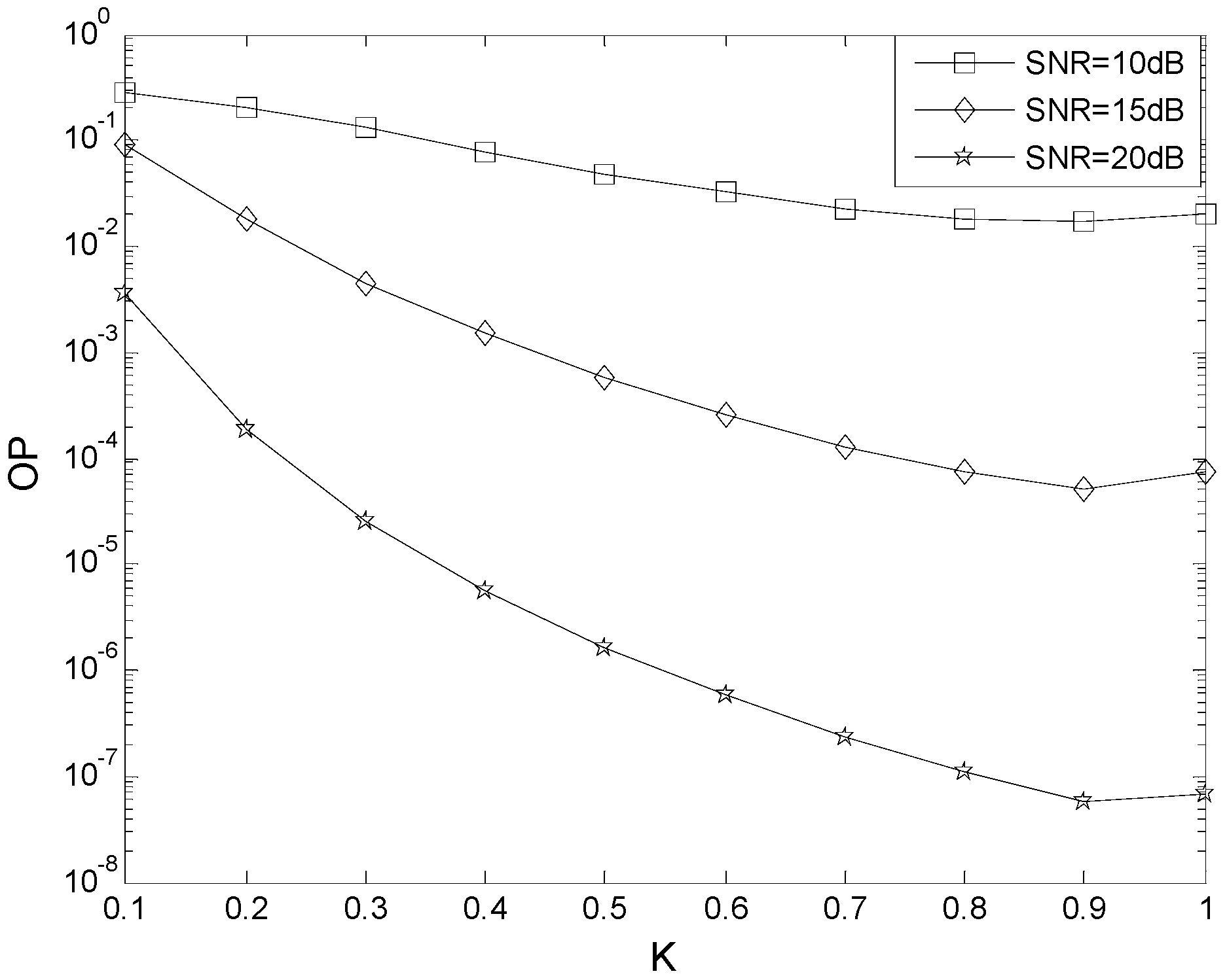
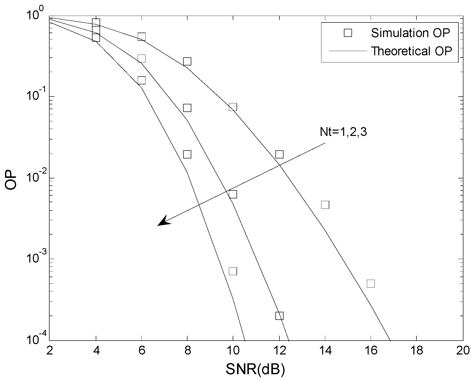
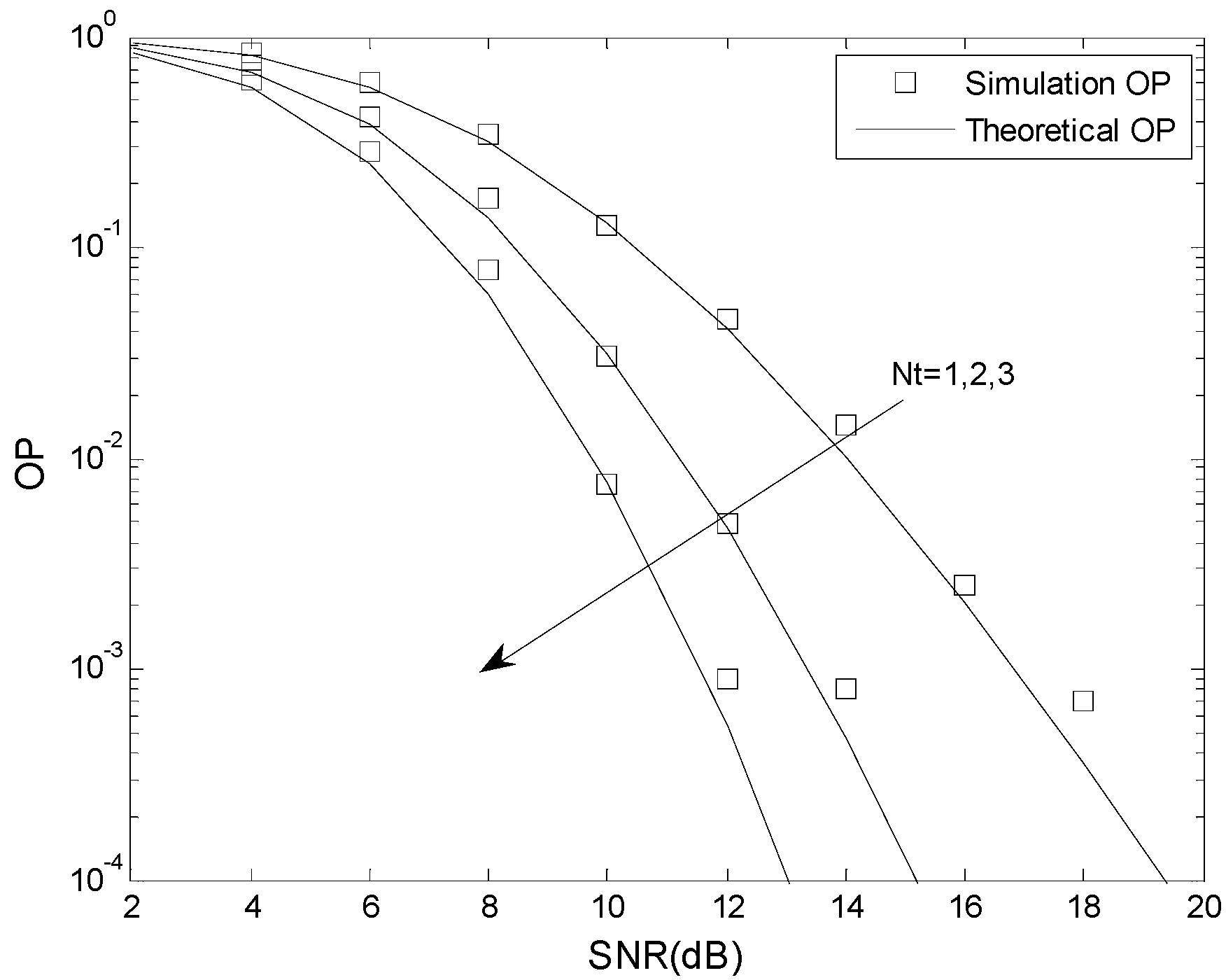
6. Numerical Results

In this section, simulation results are presented to confirm the analysis given previously. The Monte Carlo simulations were done using MATLAB, and the analytical results were verified using MAPLE. The total energy is E = 1, the fading coefficient is m = 1, 2, 3, the number of cascaded components is N = 2, 3, 4, the number of mobile relays is L = 2, the number of receive antennas is Nr = 2, the relative geometrical gain is μ = 0 dB, and the number of transmit antennas is Nt = 1, 2, 3.
Figure 4 and Figure 5 present the OP performance of the optimal TAS scheme with γth = 5 dB, γT = 2 dB and γP = 6 dB, and γth = 5 dB, γT = 2 dB and γP = 3 dB, respectively. The other parameters are N = 2, m = 2, K = 0.5, Nt = 1, 2, 3, L = 2, Nr = 2, and μ = 0 dB. This shows that the analytical results match the simulation results. The OP improves as the number of transmit antennas is increased. For example, when γth = 5 dB, γT = 2 dB, γP = 3 dB, and SNR = 10 dB, the OP is 1.1 × 10⁻¹ when Nt = 1, 1.3 × 10⁻² when Nt = 3, and 1.4 × 10⁻³ when Nt = 3. For fixed Nt, an increase in the SNR decreases the OP.
Figure 6 and Figure 7 present the OP performance of the suboptimal TAS scheme with γth = 5 dB, γT = 2 dB and γP = 6 dB, and γth = 5 dB, γT = 2 dB and γP = 3 dB, respectively. The other parameters are N = 2, m = 2, K = 0.5, Nt = 1, 2, 3, L = 2, Nr = 2, and μ = 0 dB. This also shows that the analytical results match the simulation results. As expected, the OP improves as the number of transmit antennas is increased. For example, when γth = 5 dB, γT = 2 dB, γP = 6 dB, SNR = 12 dB, and Nt = 1, the OP is 4.1 × 10⁻² when Nt = 1, 4.7 × 10⁻³ when Nt = 2, and 5.3 × 10⁻⁴ when Nt = 3, For fixed Nt, an increase in the SNR decreases the OP, as expected.
Figure 8 compares the OP performance of the optimal and suboptimal TAS schemes for different numbers of antennas Nt. The parameters are N = 2, m = 2, K = 0.5, μ = 0 dB, Nt = 2, 3, L = 2, Nr = 2, γth = 5 dB, γT = 2 dB, and γP = 3 dB. In all cases, for a given value of Nt the optimal TAS scheme has better OP performance. As predicted by the analysis, the performance gap between the two TAS schemes decreases as Nt is increased. When the SNR is low, the OP performance gap between the optimal TAS scheme with Nt = 2 and the suboptimal TAS scheme with Nt = 3 is negligible. As the SNR increases, the OP performance gap also increases.

7. Conclusions

In this paper, exact closed-form OP expressions were derived for ISDF relaying M2M networks with TAS over N-Nakagami fading channels. Performance results were presented which show that the optimal TAS scheme has better OP performance than the suboptimal scheme. It was also shown that the power allocation parameter K can have a significant effect on the OP performance. The given expressions can be used to evaluate the OP performance of inter-vehicular networks, mobile wireless sensor networks, and mobile heterogeneous networks.

Acknowledgments

The authors would like to thank the referees and editors for providing very helpful comments and suggestions. This project was supported by the National Natural Science Foundation of China (Nos. 61304222 and 61301139), and the Shandong Province Outstanding Young Scientist Award Fund (No. 2014BSE28032).

Author Contributions

The corresponding author Lingwei Xu derived the exact closed-form OP expressions for the optimal and suboptimal TAS schemes; Hao Zhang conceived and designed the experiments; T. Aaron Gulliver provided comments on the paper organization, contributed towards the performance results and analytic evaluations, and was involved in the creation of the manuscript.

Conflicts of Interest

The authors declare no conflicts of interest.

References

  1. Wu, G.; Talwar, S.; Johnsson, K.; Himayat, N.; Johnson, K.D. M2M: From mobile to embedded internet. IEEE Commun. Mag. 2011, 49, 36–43. [Google Scholar]
  2. Chen, M.; Wan, J.F.; Li, F. Machine-to-machine communications: Architectures, standards, and applications. KSII Trans. Int. Inf. Syst. 2012, 6, 480–497. [Google Scholar] [CrossRef]
  3. Jo, M.; Maksymyuk, T.; Strykhalyuk, B.; Cho, C.H. Device-to-device based heterogeneous radio access network architecture for mobile cloud computing. IEEE Wirel. Commun. 2015, 22, 50–58. [Google Scholar] [CrossRef]
  4. Mumtaz, S.; Huq, K.M.S.; Rodriguez, J. Direct mobile-to-mobile communication: Paradigm for 5G. IEEE Wirel. Commun. 2014, 21, 14–23. [Google Scholar] [CrossRef]
  5. Chen, M.; Wan, J.F.; Gonzalez, S.; Liao, X.F.; Leung, V.C.M. A survey of recent developments in home M2M networks. IEEE Commun. Surv. Tutor. 2014, 16, 98–114. [Google Scholar] [CrossRef]
  6. Talha, B.; Patzold, M. Channel models for mobile-to-mobile cooperative communication systems: A state of the art review. IEEE Veh. Technol. Mag. 2011, 6, 33–43. [Google Scholar] [CrossRef]
  7. Salo, J.; Sallabi, H.E.; Vainikainen, P. Statistical analysis of the multiple scattering radio channel. IEEE Trans. Antennas Propag. 2006, 54, 3114–3124. [Google Scholar] [CrossRef]
  8. Salo, J.; Sallabi, H.E.; Vainikainen, P. The distribution of the product of independent Rayleigh random variables. IEEE Trans. Antennas Propag. 2006, 54, 639–643. [Google Scholar] [CrossRef]
  9. Uysal, M. Diversity analysis of space-time coding in cascaded Rayleigh fading channels. IEEE Commun. Lett. 2006, 10, 165–167. [Google Scholar] [CrossRef]
  10. Karagiannidis, G.K.; Sagias, N.C.; Mathiopoulos, P.T. N-Nakagami: A novel stochastic model for cascaded fading channels. IEEE Trans. Commun. 2007, 55, 1453–1458. [Google Scholar] [CrossRef]
  11. Gong, F.K.; Ye, P.; Wang, Y.; Zhang, N. Cooperative mobile-to-mobile communications over double Nakagami-m fading channels. IET Commun. 2012, 6, 3165–3175. [Google Scholar] [CrossRef]
  12. Ilhan, H.; Uysal, M.; Altunbas, I. Cooperative diversity for intervehicular communication: Performance analysis and optimization. IEEE Trans. Veh. Technol. 2009, 58, 3301–3310. [Google Scholar] [CrossRef]
  13. Xu, L.W.; Zhang, H.; Liu, X.; Gulliver, T.A. Performance analysis of FAF relaying M2M cooperative networks over N-Nakagami fading channels. Int. J. Signal Process. Image Process. Pattern Recognit. 2015, 8, 249–258. [Google Scholar] [CrossRef]
  14. Xu, L.W.; Zhang, H.; Lu, T.T.; Liu, X.; Wei, Z.Q. Performance analysis of the mobile-relay-based M2M communication over N-Nakagami fading channels. J. Appl. Sci. Eng. 2015, 18, 309–314. [Google Scholar]
  15. Ikki, S.S.; Ahmed, M.H. Performance analysis of incremental-relaying cooperative-diversity networks over Rayleigh fading channels. IET Commun. 2011, 5, 337–349. [Google Scholar] [CrossRef]
  16. Yang, C.; Wang, W.; Chen, S.; Peng, M. Outage performance of orthogonal space-time block codes transmission in opportunistic decode-and-forward cooperative networks with incremental relaying. IET Commun. 2011, 5, 61–70. [Google Scholar] [CrossRef]
  17. Xu, L.W.; Zhang, H.; Lu, T.T.; Gulliver, T.A. Performance analysis of the IAF relaying M2M cooperative networks over N-Nakagami fading channels. J. Commun. 2015, 10, 185–191. [Google Scholar] [CrossRef]
  18. Xu, L.W.; Zhang, H.; Gulliver, T.A. Performance analysis of IDF relaying M2M cooperative networks over N-Nakagami fading channels. KSII Trans. Int. Inf. Syst. 2015, 9, 3983–4001. [Google Scholar]
  19. Chen, H.; Liu, J.; Zhai, C.; Liu, Y.X. Performance of incremental-selective decode-and-forward relaying cooperative communications over Rayleigh fading channels. In Proceedings of the Conference on Wireless Communications & Signal Processing, Nanjing, China, 13–15 November 2009; pp. 1–5.
  20. Xu, L.W.; Zhang, H.; Gulliver, T.A. Performance analysis of the SIR M2M cooperative networks. Int. J. Control Autom. 2015, 8, 407–416. [Google Scholar] [CrossRef]
  21. Suraweera, H.A.; Smithnd, P.J.; Nallanathan, A.; Thompson, J.S. Amplify-and-forward relaying with optimal and suboptimal transmit antenna selection. IEEE Trans. Wirel. Commun. 2011, 10, 1874–1885. [Google Scholar] [CrossRef]
  22. Yeoh, P.L.; Elkashlan, M.; Yang, N.; Costa, D.B.D.; Duong, T.Q. Unified analysis of transmit antenna selection in MIMO multi-relay networks. IEEE Trans. Veh. Technol. 2013, 62, 933–939. [Google Scholar] [CrossRef]
  23. Li, H.; Song, L.Y.; Debbah, M. Energy efficiency of large-scale multiple antenna systems with transmit antenna selection. IEEE Trans. Commun. 2014, 62, 638–647. [Google Scholar] [CrossRef]
  24. Zhang, H.J.; Jiang, C.X.; Beaulieu, N.C.; Chu, X.L.; Wen, X.M.; Tao, M.X. Resource Allocation in Spectrum-Sharing OFDMA Femtocells with Heterogeneous Services. IEEE Trans. Commun. 2014, 62, 2366–2377. [Google Scholar] [CrossRef]
  25. Zhang, H.J.; Jiang, C.X.; Beaulieu, N.C.; Chu, X.L.; Wang, X.B.; Quek, T.Q.S. Resource Allocation for Cognitive Small Cell Networks: A Cooperative Bargaining Game Theoretic Approach. IEEE Trans. Wirel. Commun. 2015, 14, 3481–3493. [Google Scholar] [CrossRef]
  26. Zhang, H.J.; Jiang, C.X.; Mao, X.T.; Chen, H.H. Interference-Limit Resource Optimization in Cognitive Femtocells with Fairness and Imperfect Spectrum Sensing. IEEE Trans. Veh. Technol. 2015. [Google Scholar] [CrossRef]
  27. Zhang, H.J.; Xing, H.; Cheng, J.L.; Nallanathan, A.; Leung, V.C.M. Secure Resource Allocation for OFDMA Two-Way Relay Wireless Sensor Networks Without and With Cooperative Jamming. IEEE Trans. Ind. Inform. 2015. [Google Scholar] [CrossRef]
  28. Ochiai, H.; Mitran, P.; Tarokh, V. Variable-rate two-phase collaborative communication protocols for wireless networks. IEEE Trans. Veh. Technol. 2006, 52, 4299–4313. [Google Scholar] [CrossRef]
Figure 1. The system model.
Sensors 16 00249 g001
Figure 2. The effect of the power allocation parameter K on the OP performance.
Sensors 16 00249 g002
Figure 3. The effect of the relative geometrical gain μ on the OP performance.
Sensors 16 00249 g003
Figure 4. The OP performance of the optimal TAS scheme when γth < γP.
Sensors 16 00249 g004
Figure 5. The OP performance of the optimal TAS scheme when γth > γP.
Sensors 16 00249 g005
Figure 6. The OP performance of the suboptimal TAS scheme when γth < γP.
Sensors 16 00249 g006
Figure 7. The OP performance of the suboptimal TAS scheme when γth > γP.
Sensors 16 00249 g007
Figure 8. The OP performance of the optimal and suboptimal TAS schemes for different numbers of antennas Nt.
Sensors 16 00249 g008
Table 1. OPA parameters K.
SNR (dB)μ = 5 dBμ = 0 dBμ = −5 dB
50.990.410.51
100.510.410.47
150.500.440.45
200.500.470.46

