A Rapid Coordinate Transformation Method Applied in Industrial Robot Calibration Based on Characteristic Line Coincidence
Abstract
:1. Introduction
2. Online Calibration System of Robot
3. Methods of Online Calibration System
3.1. Method of Coordinate Transformation
- (a)
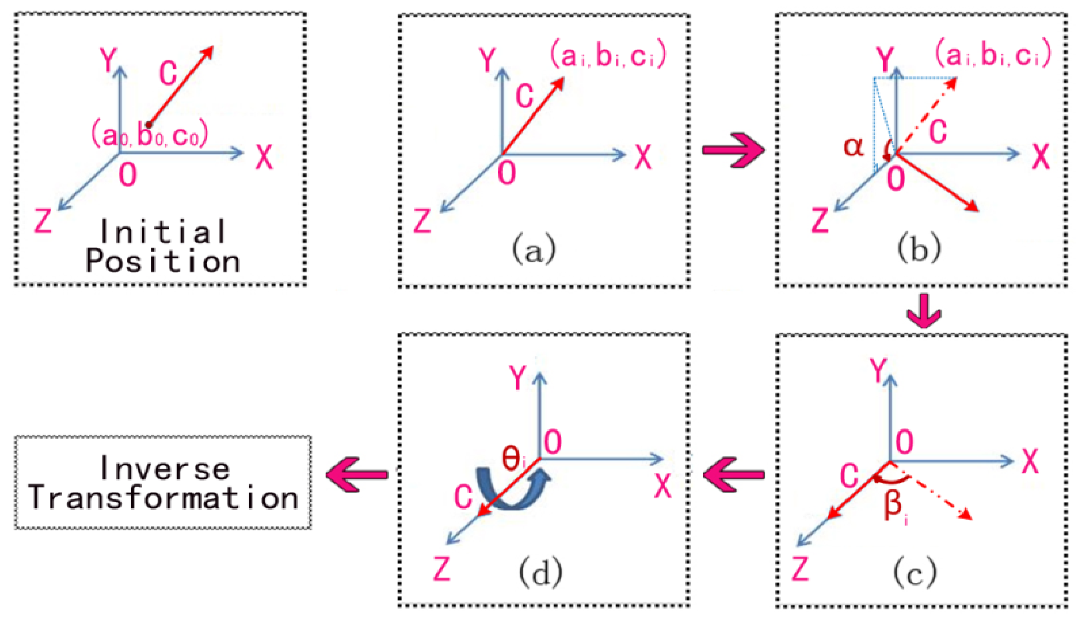
- Translate the rotation axis to the coordinate origin. The corresponding transformation matrix can be calculated as:where, (a0, b0, c0) is the coordinates of the center point of line A.
- (b)
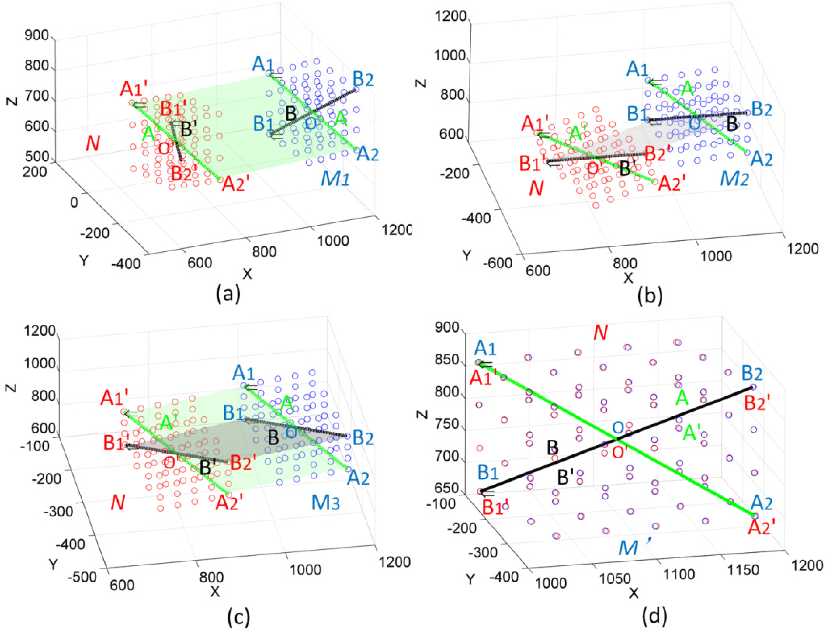
- Rotate the axis α1 degrees to Plane XOZ.is the angle between the axis and plane XOZ. It can be obtained by , , where, (a1, b1, c1) are the coordinates of vector C, as Figure 3b shows.
- (c)
- Rotate the axis β1 degrees to coincide with Axis Z.where, is the angle between the rotation axis and axis Z. It can be obtained by .
- (d)
- Rotate the axis degrees around Axis Z, as shown in Figure 3d.where is the angle between lines A and A', which can be obtained by .
- (e)
- Rotate the axis by reversing the process of Step (c)where, is as the same as in step (c).
- (f)
- Rotate the axis by reversing the process of Step (b).where, is as the same as in step (b).
- (g)
- Rotate the axis by reversing the process of Step (a)where, (a0, b0, c0) is as the same as in step (a).
3.2. Method of Robot Calibration
4. Experiments and Analysis
4.1. Coordinate Transformationin an On-line Robot Calibration System
4.2. Position Error of Robot after Coordinate Transformation and Calibration
4.3. Accuracy of Coordinate Transformation Method
5. Conclusions
Acknowledgments
Author Contributions
Conflicts of Interest
References
- Wang, F.; Wei, X.Z.; Li, X. Coordinates transformation and the accuracy analysis in sensor network. J. Syst. Eng. Electron. 2005, 27, 1231–1234. [Google Scholar]
- Lin, J.R. Research on the Combined Measurement Method of Large Complex Objects Malcolm. Ph.D. Thesis, Tianjin University, Tianjin, China, May 2012; pp. 54–72. [Google Scholar]
- Davis, M.H.; Khotanzad, A.; Flamig, D.P.; Harms, S.E. A physics-based coordinate transformation for 3-D image matching. IEEE Trans. Med. Imaging 1997, 16, 317–328. [Google Scholar] [CrossRef] [PubMed]
- Huang, F.S.; Chen, L. CCD camera calibration technology based on the translation of coordinate measuring machine. Appl. Mech. Mater. 2014, 568–570, 320–325. [Google Scholar] [CrossRef]
- Liu, C.J.; Chen, Y.W.; Zhu, J.G.; Ye, S.H. On-line flexible coordinate measurement system based on an industry robot. J. Optoelectron. Laser 2010, 21, 1817–1821. [Google Scholar]
- Stein, D.; Monnich, H.; Raczkowsky, J.; Worn, H. Automatic and hand guided self-registration between a robot and an optical tracking system. In Proceedings of the International Conference on Advanced Robotics (ICAR), Munich, Germany, 22–26 June 2009; pp. 22–26.
- Jian, Y.Z.; Chen, Z.; Da, W.Z. Pose accuracy analysis of robot manipulators based on kinematics. Adv. Manuf. Syst. 2011, 201–203, 1867–1872. [Google Scholar]
- Denavit, J.; Hartenberg, R.S. A kinematic notation for lower-pair mechanisms based on matrices. ASME. J. Appl. Mech. 1955, 22, 215–221. [Google Scholar]
- Hayati, S.A. Robot arm geometric link parameter estimation. In Proceedings of the 22nd IEEE Conference on Decision and Control, San Antonio, TX, USA, 14–16 December 1983.
- Du, G.; Zhang, P. Online serial manipulator calibration based on multisensory process via extended Kalman and particle filters. IEEE Trans. Ind. Electron. 2014, 61, 6852–6859. [Google Scholar]
- Hans, D.R.; Beno, B. Visual-model-based, real-time 3D pose tracking for autonomous navigation: Methodology and experiments. Auton. Robot 2008, 25, 267–286. [Google Scholar]
- Yang, F.; Li, G.Y.; Wang, L. Research on the Methods of Calculating 3D Coordinate Transformation Parameters. Bull. Surv. Mapp. 2010, 6, 5–7. [Google Scholar]
- Zhang, H.; Yao, C.Y.; Ye, S.H.; Zhu, J.G.; Luo, M. The Study on Spatial 3-D Coordinate Measurement Technology. Chin. J. Sci. Instrum. 2004, 22, 41–43. [Google Scholar]
- Yang, F.; Li, G.Y.; Wang, L.; Yu, Y. A method of least square iterative coordinate transformation based on Lodrigues matrix. J. Geotech. Investig. Surv. 2010, 9, 80–84. [Google Scholar]
- Chen, X.J.; Hua, X.H.; Lu, T.D. Detection of exceptional feature points based on combined Rodrigo matrix. Sci. Surv. Mapp. 2013, 38, 94–96. [Google Scholar]
- Nicolas, L.B.; Stephen, J.S. Jacobi method for quaternion matrix singular value decomposition. Appl. Math. Comput. 2007, 187, 1265–1271. [Google Scholar]
- Ni, Z.S.; Liao, Q.Z.; Wu, X.X. General 6Rrobot inverse solution algorithm based on a quaternion matrix and a Groebner base. J. Tsinghua Univ. (Sci. Tech.) 2013, 53, 683–687. [Google Scholar]
- Weng, J.; Huang, T.S.; Ahuja, N. Motion and structure from two perspective views: Algorithms, error analysis, and error estimation. IEEE Trans. Pattern Anal. 1989, 11, 451–476. [Google Scholar] [CrossRef]
- Zhang, B.; Wei, Z.; Zhang, G.J. Rapid coordinate transformation between a robot and a laser tracker. Chin. J. Sci. Instrum. 2012, 9, 1986–1990. [Google Scholar]
- Li, R.; Qu, X.H. Study on calibration uncertainty of industrial robot kinematics parameters. Chin. J. Sci. Instrum. 2014, 35, 2192–2199. [Google Scholar]
- Liu, B.L.; Zhang, F.M.; Qu, X.H. A method for improving the pose accuracy of a robot manipulator based on multi-sensor combined measurement and data fusion. Sensors 2015, 15, 7933–7952. [Google Scholar] [CrossRef] [PubMed]
| Robot to Photogrammetric System | Robot to Laser Tracker | ||||||||||
|---|---|---|---|---|---|---|---|---|---|---|---|
| a1 | b1 | c1 | α1 | β1 | θ1 | a1 | b1 | c1 | α1 | β1 | θ1 |
| −2588.9 | 81326 | −62472 | 127.53° | 1.4461° | 256.282° | −3.0135 | 11.132 | −5.8921 | 117.89° | 13.456° | 0.007° |
| a2 | b2 | c2 | α2 | β2 | θ2 | a2 | b2 | c2 | α2 | β2 | θ2 |
| −30491 | −39586 | 1397.2 | 87.979° | 37.588° | 208.161° | −6.143 | 0.26899 | −5.9267 | 177.4° | 45.997° | 0.004° |
| a3 | b3 | c3 | α3 | β3 | θ3 | a3 | b3 | c3 | α3 | β3 | θ3 |
| 210.37 | −155.16 | 194.69 | 38.555° | 40.198° | 176.953° | 200.03 | 159.99 | −200.07 | 141.35° | 37.984° | 0.005° |
| Robot to Photogrammetric System | Robot to Laser Tracker | ||||||||||
|---|---|---|---|---|---|---|---|---|---|---|---|
| Photogrammetric system | Robot | Laser tracker | Robot | ||||||||
| Px | Py | Pz | Rx | Ry | Rz | Lx | Ly | Lz | Rx | Ry | Rz |
| 42.728 | 138.567 | 109.566 | 895 | 30 | 875 | 1048.620 | 29.944 | 875.077 | 895 | 30 | 875 |
| 108.751 | 140.724 | 108.418 | 961 | 30 | 875 | 1114.679 | 29.985 | 874.995 | 961 | 30 | 875 |
| 175.846 | 143.007 | 107.153 | 1028 | 30 | 875 | 1181.646 | 29.955 | 874.989 | 1028 | 30 | 875 |
| 242.882 | 145.388 | 105.845 | 1095 | 30 | 875 | 1248.689 | 29.935 | 874.791 | 1095 | 30 | 875 |
| 76 points are ignored | 76 points are ignored | ||||||||||
| Transformation result | error | Transformation result | error | ||||||||
| Tx | Ty | Tz | Δx | Δy | Δz | Tx | Ty | Tz | Δx | Δy | Δz |
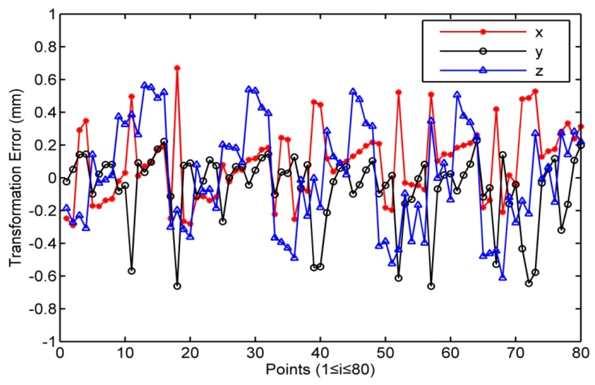
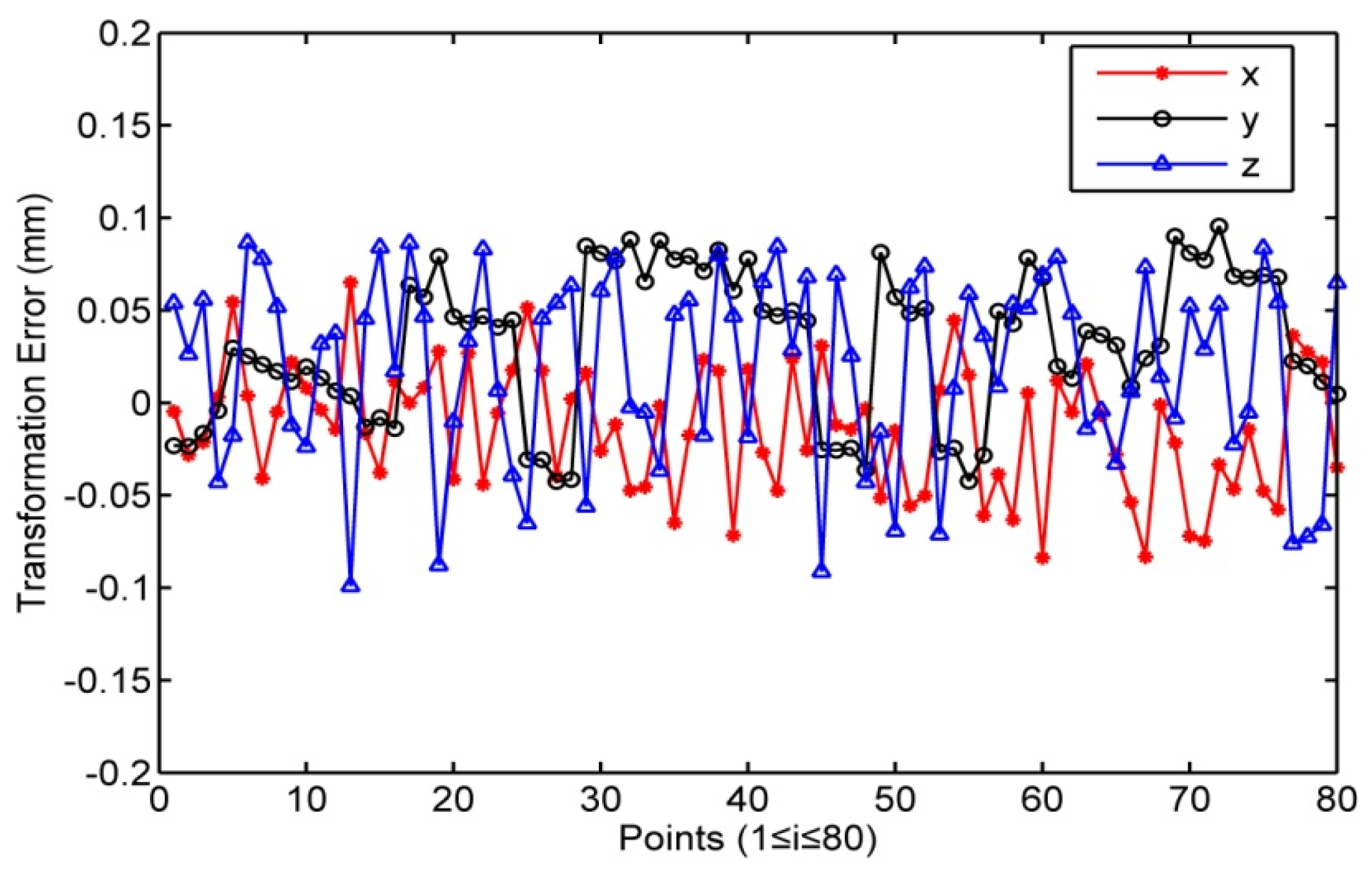
| 42.975 | 138.590 | 109.751 | −0.247 | −0.023 | −0.185 | 1048.624 | 29.967 | 875.024 | −0.004 | −0.023 | 0.053 |
| 108.921 | 140.822 | 108.277 | −0.170 | −0.098 | 0.141 | 1114.625 | 29.956 | 875.012 | 0.054 | 0.029 | −0.017 |
| 175.866 | 143.088 | 106.780 | −0.020 | −0.081 | 0.373 | 1181.624 | 29.944 | 875.001 | 0.022 | 0.011 | −0.012 |
| 242.812 | 145.355 | 105.282 | 0.070 | 0.033 | 0.563 | 1248.624 | 29.932 | 874.890 | 0.065 | 0.003 | −0.099 |
| 76 points are ignored | 76 points are ignored | ||||||||||
| Region | O | O1 | O2 | O3 | O4 | O5 |
|---|---|---|---|---|---|---|
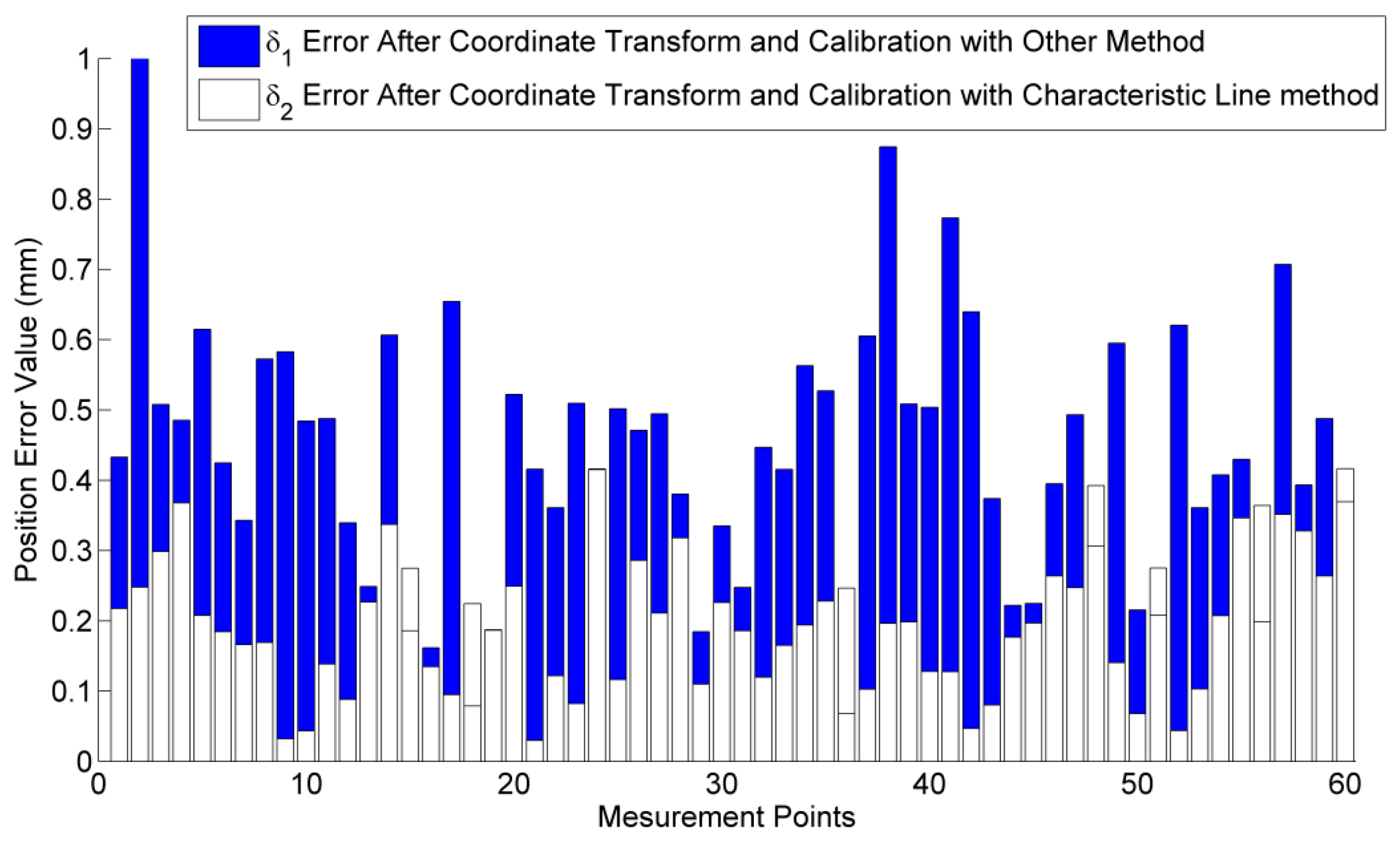
| Position error/mm | 0.200 | 0.330 | 0.360 | 0.271 | 0.335 | 0.319 |
| Points | Station 1 | Station 2 | ||||
| x/mm | y/mm | z/mm | x/mm | y/mm | z/mm | |
| 1 | 3049.626 | −188.668 | −1403.555 | 1484.68 | 1639.268 | −1401.164 |
| 2 | 4247.93 | 991.939 | −1401.334 | 1050.101 | 3264.365 | −1396.089 |
| 3 | 1678.935 | 1946.842 | −1380.022 | −1049.19 | 1502.397 | −1379.453 |
| 4 | 3688.375 | 2777.637 | −1403.824 | −778.88 | 3659.965 | −1398.95 |
| 5 | 3802.578 | 1207.190 | −1397.241 | 642.931 | 2983.472 | −1392.788 |
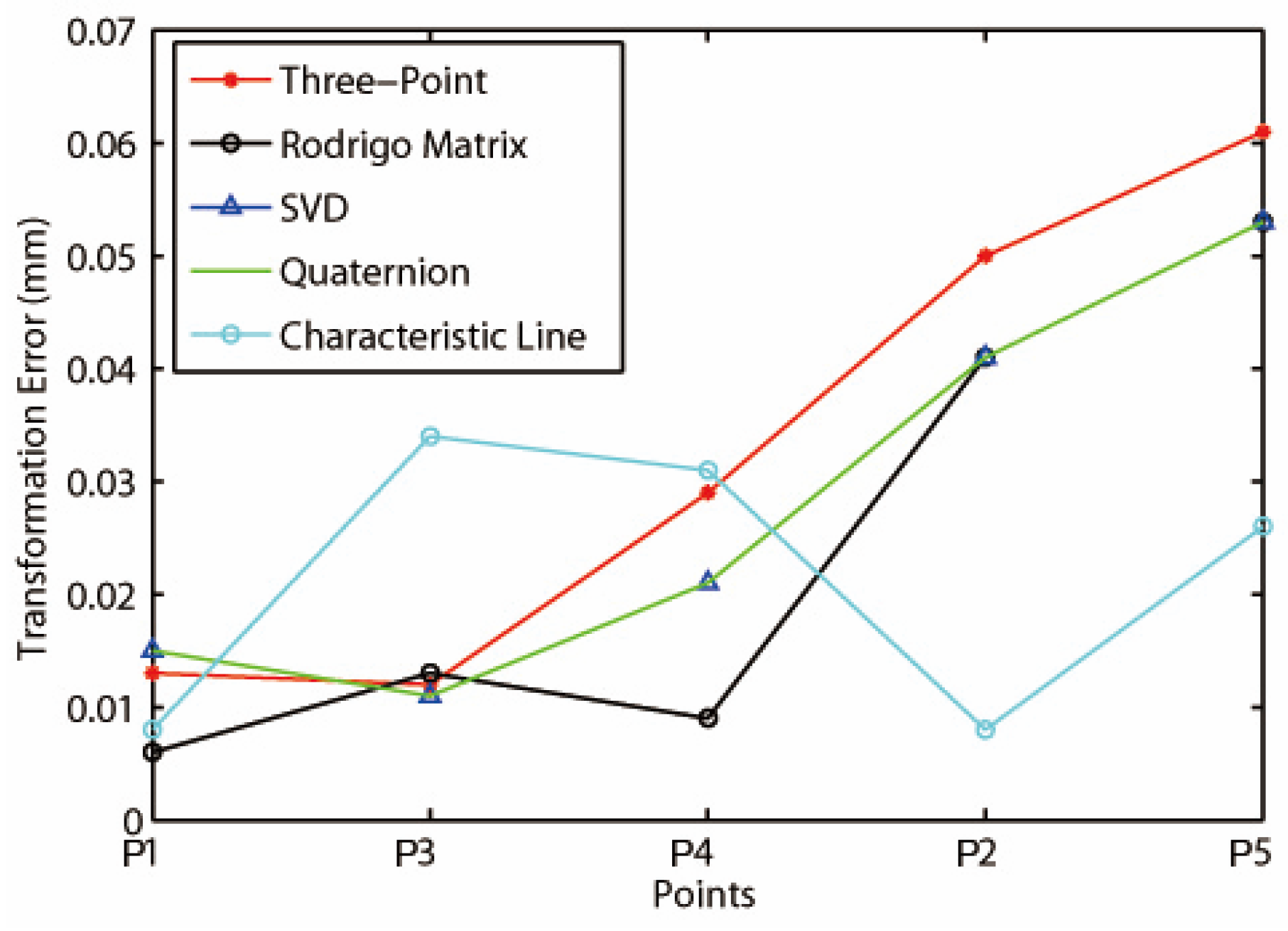
| Points | Three-Point | Rodrigo Matrix | SVD | Quaternion | Characteristic Line | |
| RMS/mm | RMS/mm | RMS/mm | RMS/mm | RMS/mm | ||
| 1 | 0.013 | 0.006 | 0.015 | 0.015 | 0.008 | |
| 2 | 0.050 | 0.041 | 0.041 | 0.041 | 0.008 | |
| 3 | 0.012 | 0.013 | 0.011 | 0.011 | 0.034 | |
| 4 | 0.029 | 0.009 | 0.021 | 0.021 | 0.031 | |
| 5 | 0.061 | 0.053 | 0.053 | 0.053 | 0.026 | |
| 0.033 | 0.024 | 0.027 | 0.028 | 0.025 | ||
| Execution time/s | 0.021 | 0.203 | 0.031 | 0.023 | 0.029 | |
© 2016 by the authors; licensee MDPI, Basel, Switzerland. This article is an open access article distributed under the terms and conditions of the Creative Commons by Attribution (CC-BY) license (http://creativecommons.org/licenses/by/4.0/).
Share and Cite
Liu, B.; Zhang, F.; Qu, X.; Shi, X. A Rapid Coordinate Transformation Method Applied in Industrial Robot Calibration Based on Characteristic Line Coincidence. Sensors 2016, 16, 239. https://doi.org/10.3390/s16020239
Liu B, Zhang F, Qu X, Shi X. A Rapid Coordinate Transformation Method Applied in Industrial Robot Calibration Based on Characteristic Line Coincidence. Sensors. 2016; 16(2):239. https://doi.org/10.3390/s16020239
Chicago/Turabian StyleLiu, Bailing, Fumin Zhang, Xinghua Qu, and Xiaojia Shi. 2016. "A Rapid Coordinate Transformation Method Applied in Industrial Robot Calibration Based on Characteristic Line Coincidence" Sensors 16, no. 2: 239. https://doi.org/10.3390/s16020239
APA StyleLiu, B., Zhang, F., Qu, X., & Shi, X. (2016). A Rapid Coordinate Transformation Method Applied in Industrial Robot Calibration Based on Characteristic Line Coincidence. Sensors, 16(2), 239. https://doi.org/10.3390/s16020239


