
Design and Optimization of a Hybrid-Driven Waist Rehabilitation Robot


Abstract
:1. Introduction
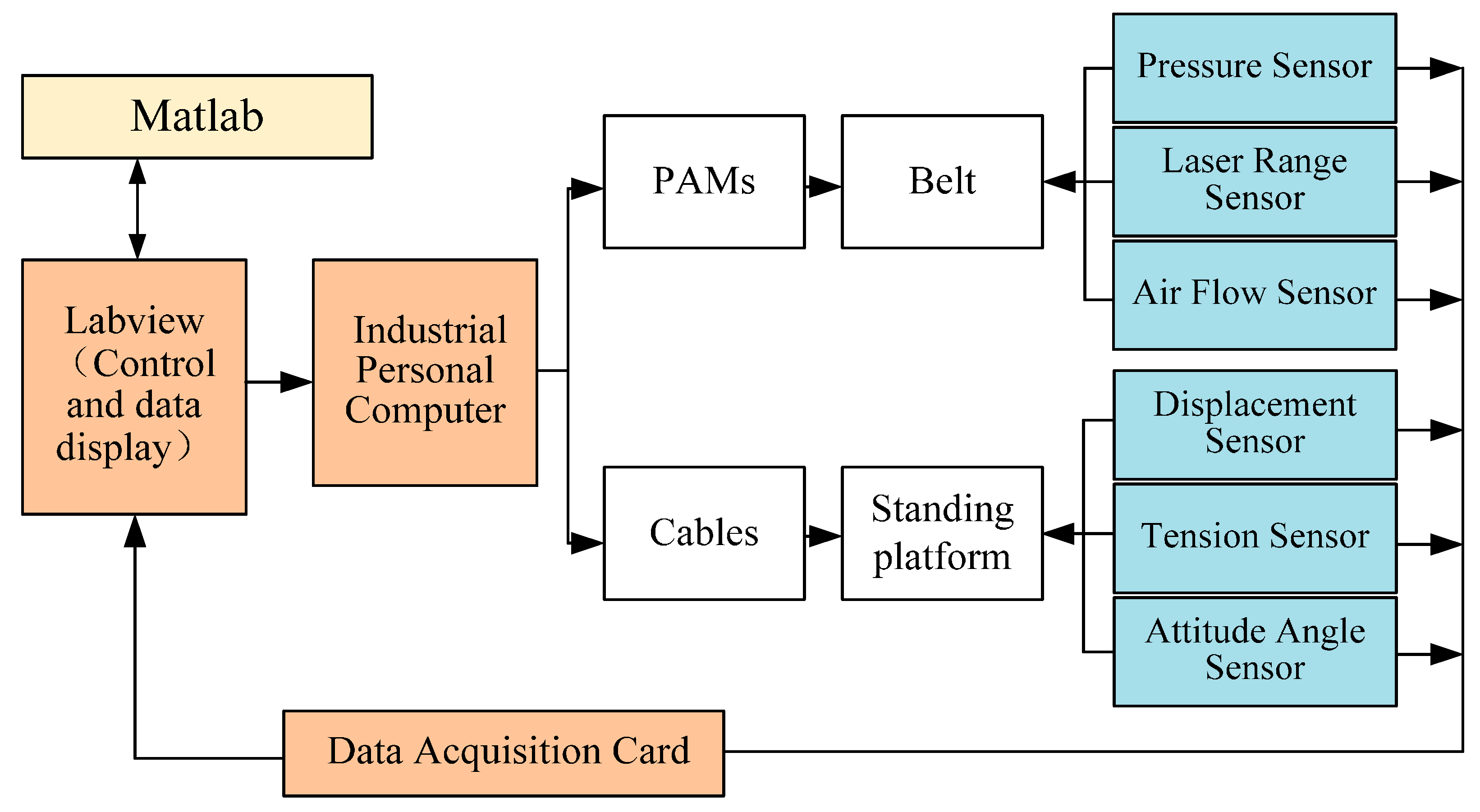
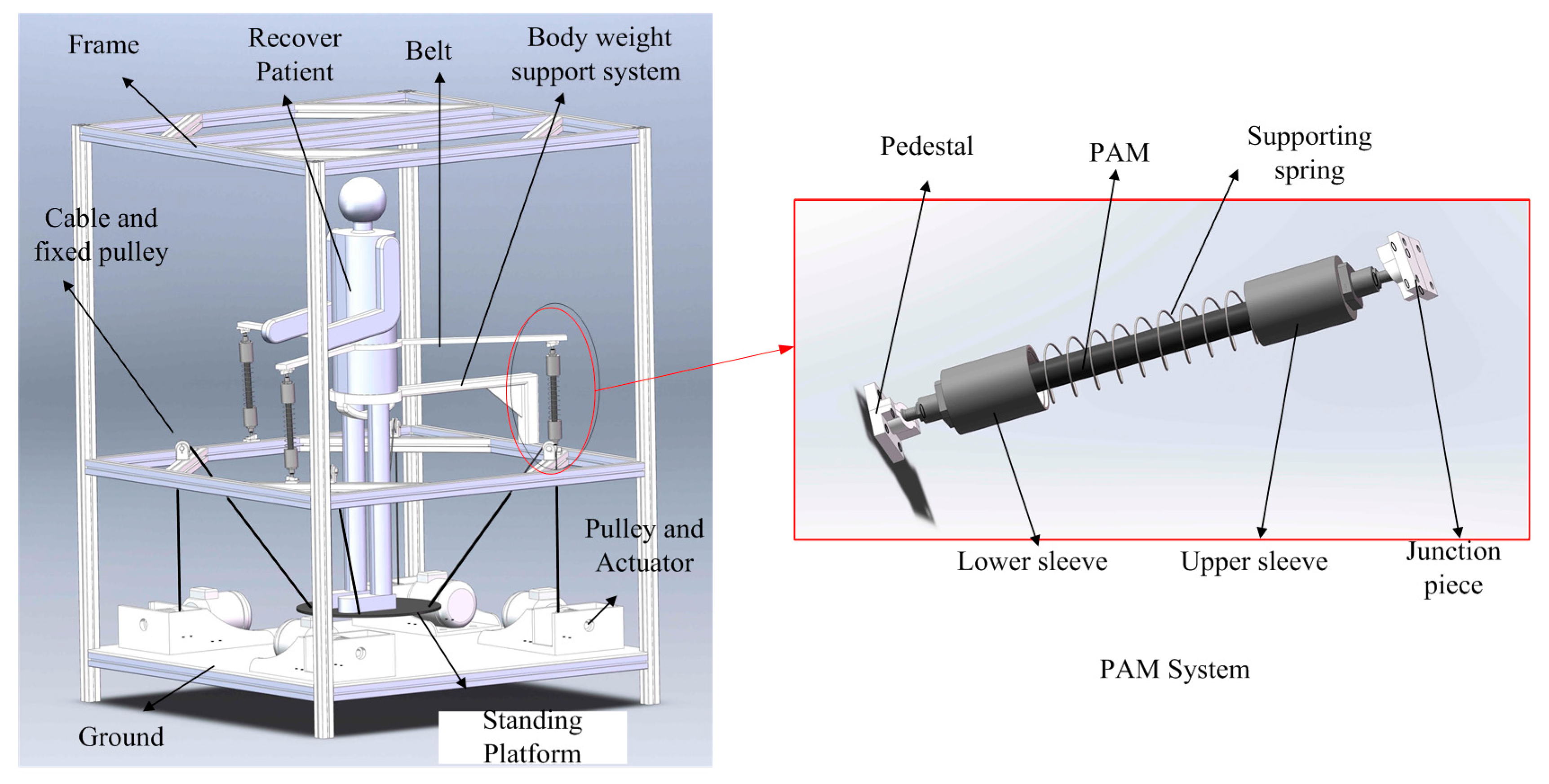
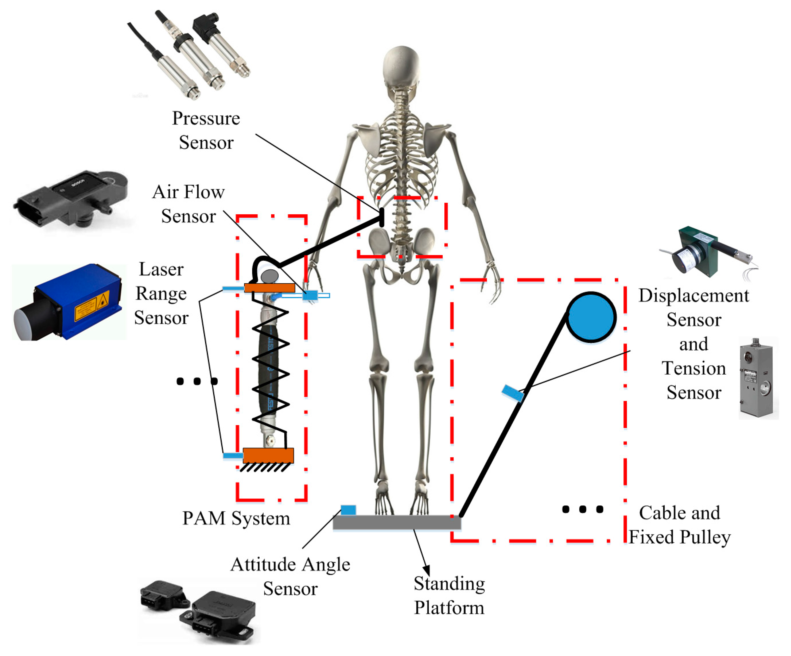
2. Structure Design
3. Inverse Kinematics and Statics
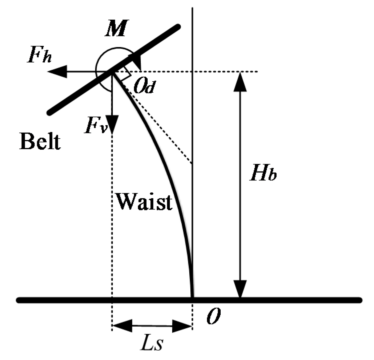
3.1. Inverse Kinematics and Statics of the Waist Twist Device
- ,
- ,
- ,
- ,
- ,
- ,
- ,
- ,
- .
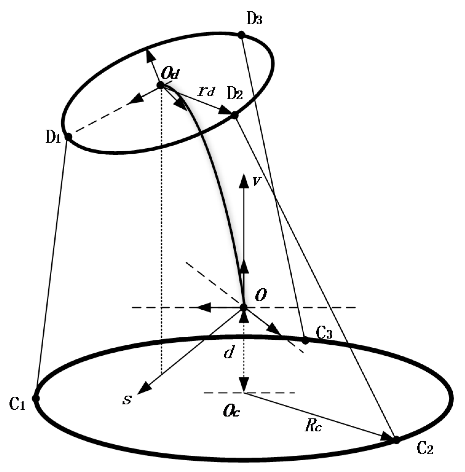
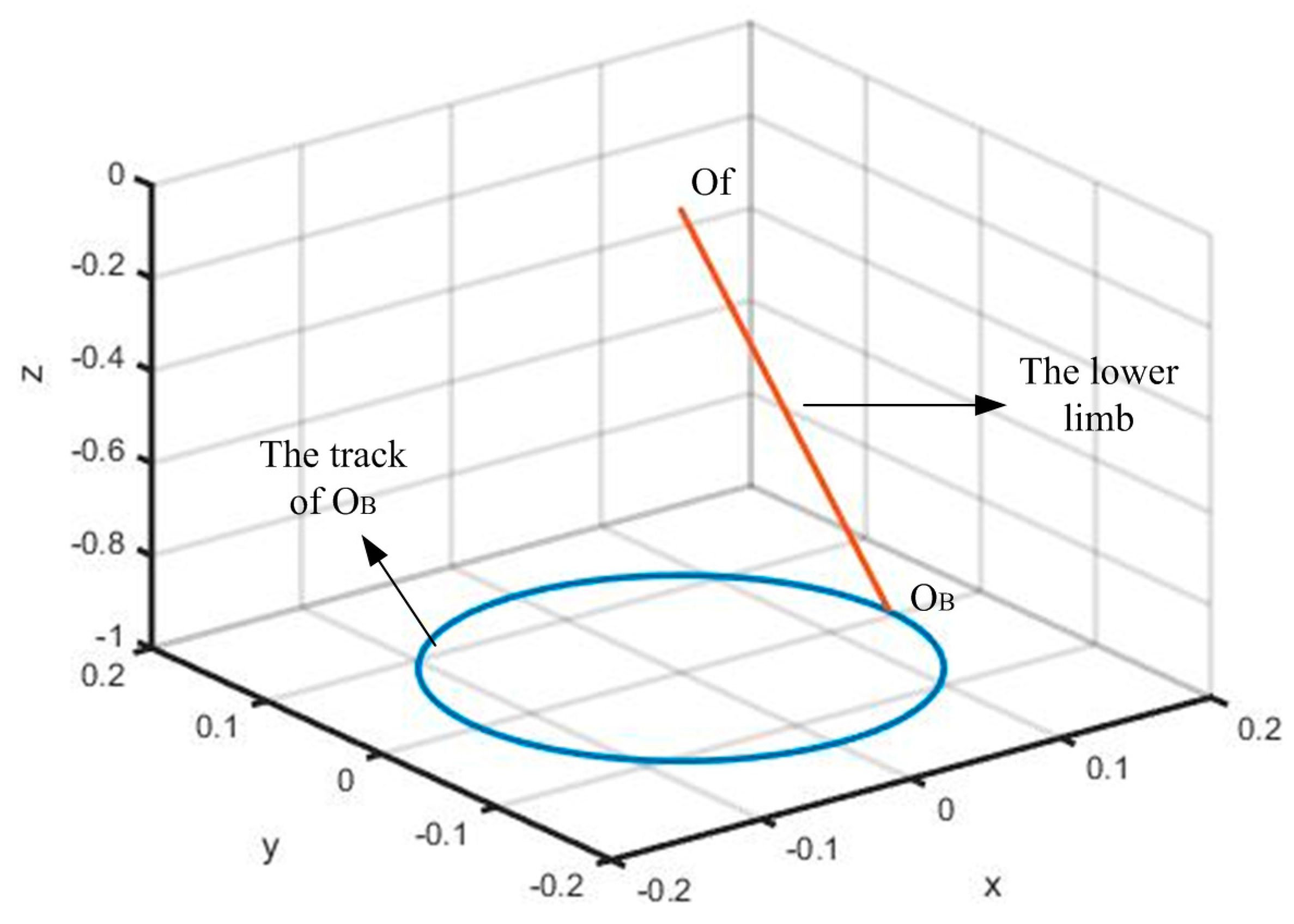
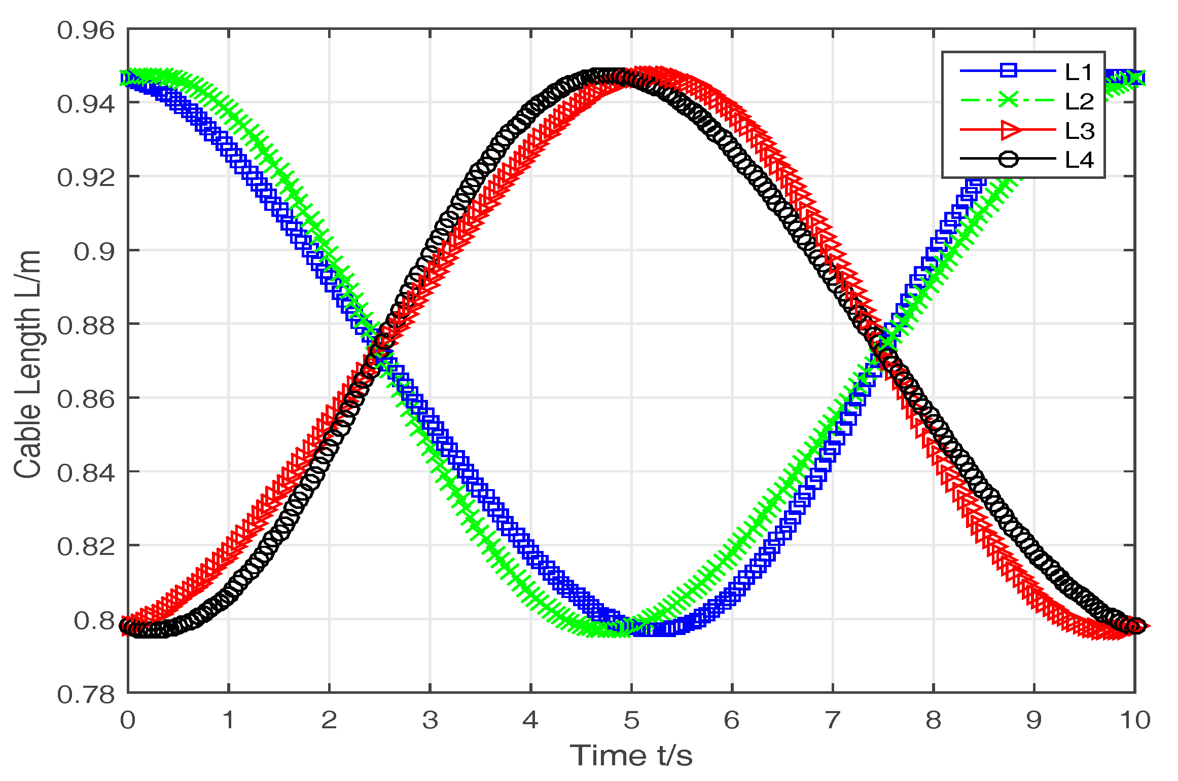
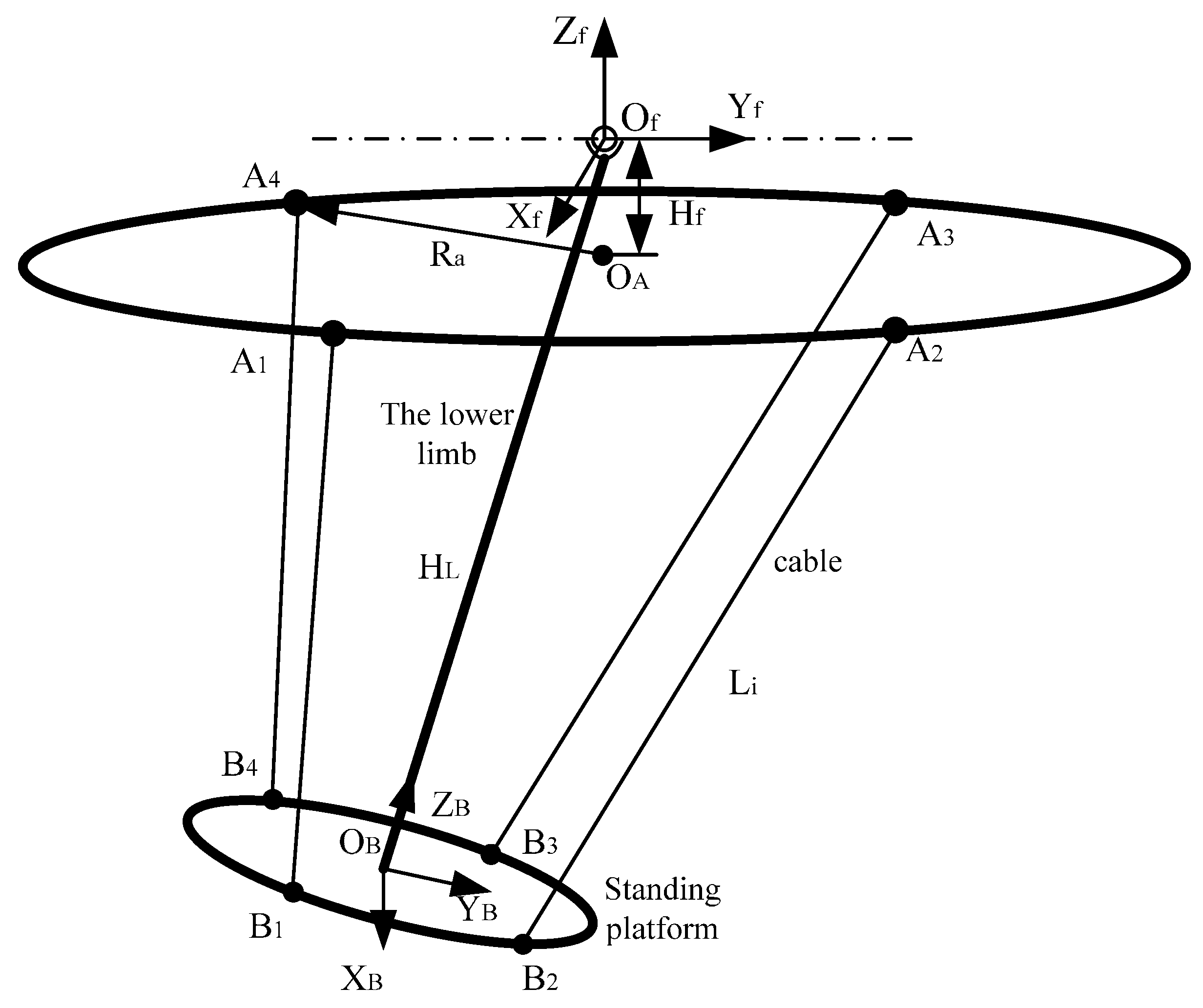
3.2. Inverse Kinematics and Statics of the Lower Limb Traction Device
4. Optimization
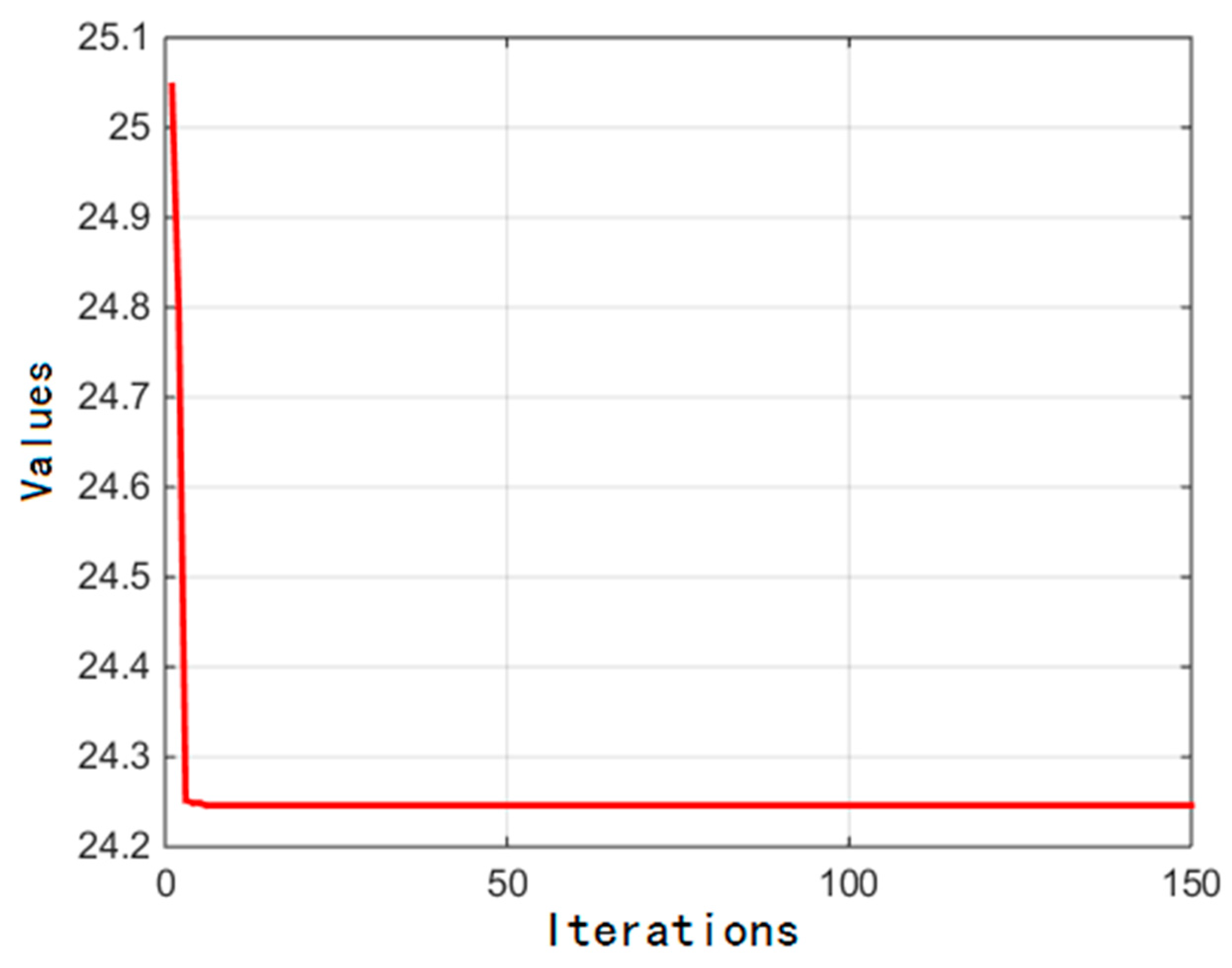
4.1. Optimization of the Waist Twist Device
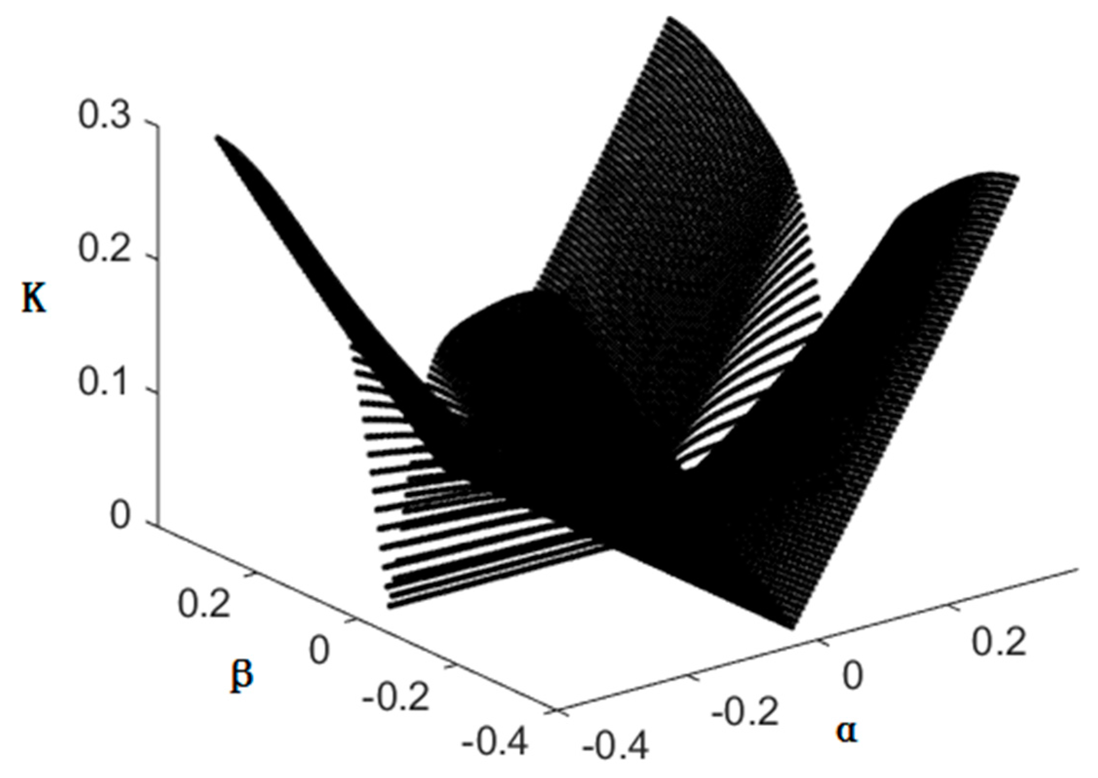
4.2. Optimization of The Lower Limb Traction Device
5. Conclusions
Acknowledgments
Conflicts of Interest
Nomenclature
| point of junction between PAM system and frame | |
| point of junction between PAM system and belt | |
| radius of the circle center round | |
| radius of the circle center round | |
| distance between point and point | |
| angle between axis s and axis X | |
| angle between the horizontal plane and the belt | |
| vertical length of the bending waist | |
| the s coordinate for in frame | |
| PAM system length | |
| perpendicular force acted on the belt | |
| force acted on the belt in the plane | |
| M | torque acted on the belt |
| K | the waist equivalent stiffness |
| the initial length of the equivalent spring of the waist | |
| point of junction between cable and frame | |
| point of junction between cable and the standing platform | |
| radius of the circle center round | |
| radius of the circle center round | |
| cable length | |
| α | angle between the standing platform and plane |
| β | angle between the standing platform and plane |
| γ | angle between the standing platform and plane |
| cable tension | |
| the resultant torque acted on the standing platform by the lower limb | |
| Jacbian matrix of the cable-driven parallel robot | |
| workspace | |
| the singular values of the Jacobian matrix |
References
- Zanotto, D.; Rosati, G.; Minto, S.; Rossi, A. Sophia-3: A Semiadaptive Cable-Driven Rehabilitation Device with a Tilting Working Plane. IEEE Trans. Robot. 2014, 30, 974–979. [Google Scholar] [CrossRef]
- Zi, B.; Duan, B.Y.; Du, J.; Bao, H.Y. Dynamic Modeling and Active Control of a Cable-Suspended Parallel Robot. Mechatronics 2008, 18, 1–12. [Google Scholar] [CrossRef]
- Zi, B.; Lin, J.; Qian, S. Localization, Obstacle Avoidance Planning and Control of a Cooperative Cable Parallel Robot for Multiple Mobile Cranes. Robot. CIM-Int. Manuf. 2015, 34, 105–123. [Google Scholar] [CrossRef]
- Qian, S.; Zi, B.; Ding, H. Dynamics and Trajectory Tracking Control of Cooperative Multiple Mobile Cranes. Nonlinear Dyn. 2016, 83, 89–108. [Google Scholar] [CrossRef]
- Surdilovic, D.; Bernhardt, R. STRING-MAN: A New Wire Robot for Gait Rehabilitation. IEEE Int. Conf. Robot. 2004, 2, 2031–2036. [Google Scholar]
- Trevisani, A. Underconstrained Planar Cable-Direct-Driven Robots: A Trajectory Planning Method Ensuring Positive and Bounded Cable Tensions. Mechatronics 2010, 20, 113–127. [Google Scholar] [CrossRef]
- Mao, Y.; Jin, X.; Dutta, G.G.; Scholz, J.P.; Agrawal, S.K. Human Movement Training with a Cable Driven ARm EXoskeleton (CAREX). IEEE Trans. Neural Syst. Rehabil. 2015, 23, 84–92. [Google Scholar] [CrossRef] [PubMed]
- Zhao, X.; Zi, B. Design and Analysis of a Pneumatic Muscle Driven Parallel Mechanism for Imitating Human Pelvis. Proc. Inst. Mech. Eng. C J. Mech. 2013, 228, 723–741. [Google Scholar] [CrossRef]
- Sarosi, J.; Biro, I.; Nemeth, J.; Cveticanin, L. Dynamic Modeling of a Pneumatic Muscle Actuator with Two-Direction Motion. Mech. Mach. Theory 2015, 85, 25–34. [Google Scholar] [CrossRef]
- Jamwal, P.K.; Xie, S.Q.; Hussain, S.; Parsons, J. An Adaptive Wearable Parallel Robot for the Treatment of Ankle Injuries. IEEE-ASME Trans. Mech. 2014, 19, 64–75. [Google Scholar] [CrossRef]
- Jamwal, P.K.; Xie, S.Q.; Aw, K.C. Kinematic Design Optimization of a Parallel Ankle Rehabilitation Robot Using Modified Genetic Algorithm. Robot. Auton. Syst. 2009, 57, 1018–1027. [Google Scholar] [CrossRef]
- Yoon, J.; Novandy, B.; Yoon, C.; Park, K. A 6-DOF Gait Rehabilitation Robot With Upper and Lower Limb Connections That Allows Walking Velocity Updates on Various Terrains. IEEE-ASME Trans. Mech. 2010, 15, 201–215. [Google Scholar] [CrossRef]
- Kong, K.; Moon, H.; Jeon, D.; Tomizuka, M. Control of an Exoskeleton for Realization of Aquatic Therapy Effects. IEEE-ASME Trans. Mech. 2010, 15, 191–200. [Google Scholar] [CrossRef]
- Gao, B.; Song, H.; Zhao, J.; Guo, S.; Sun, L.; Tang, Y. Inverse Kinematics and Workspace Analysis of a Cable-Driven Parallel Robot with a Spring Spine. Mech. Mach. Theory 2014, 76, 56–69. [Google Scholar] [CrossRef]
- Liang, C.; Ceccarelli, M. Design and Simulation of a Waist–Trunk System for a Humanoid Robot. Mech. Mach. Theory 2012, 53, 50–65. [Google Scholar] [CrossRef]
- Prange, G.B.; Jannink, M.J.; Groothuis-Oudshoorn, C.G.; Hermens, H.J.; IJzerman, M.J. Systematic Review of the Effect of Robot-aided Therapy on Recovery of the Hemiparetic Arm After Stroke. J. Rehabil. Res. Dev. 2006, 43, 171. [Google Scholar] [CrossRef] [PubMed]
- Timoshenko, S.P. Theory of Elastic Stability; McGraw-Hill: New York, NY, USA, 1961. [Google Scholar]
- Seriani, S.; Seriani, M.; Gallina, P. Workspace Optimization for a Planar Cable-Suspended Direct-Driven Robot. Robot. CIM-Int. Manuf. 2015, 34, 1–7. [Google Scholar] [CrossRef]
- Gosselin, C.; Lavoie, E. On the Kinematic Design of Spherical Three-Degree-of-Freedom Parallel Manipulators. Int. J. Robot. Res. 1993, 12, 394–402. [Google Scholar] [CrossRef]
- Parsopoulos, K.E.; Vrahatis, M.N. Particle Swarm Optimization Method in Multi-objective Problems. In Proceedings of the 2002 ACM Symposium on Applied Computing, Madrid, Spain, 10–14 March 2002; pp. 603–607.


| The Initial Length | |
| the mean diameter | |
| the pitch | |
| the shearing modulus | |
| the elastic modulus | |
| the diameter of the spring wire |
© 2016 by the authors; licensee MDPI, Basel, Switzerland. This article is an open access article distributed under the terms and conditions of the Creative Commons Attribution (CC-BY) license (http://creativecommons.org/licenses/by/4.0/).
Share and Cite
Zi, B.; Yin, G.; Zhang, D. Design and Optimization of a Hybrid-Driven Waist Rehabilitation Robot. Sensors 2016, 16, 2121. https://doi.org/10.3390/s16122121
Zi B, Yin G, Zhang D. Design and Optimization of a Hybrid-Driven Waist Rehabilitation Robot. Sensors. 2016; 16(12):2121. https://doi.org/10.3390/s16122121
Chicago/Turabian StyleZi, Bin, Guangcai Yin, and Dan Zhang. 2016. "Design and Optimization of a Hybrid-Driven Waist Rehabilitation Robot" Sensors 16, no. 12: 2121. https://doi.org/10.3390/s16122121
APA StyleZi, B., Yin, G., & Zhang, D. (2016). Design and Optimization of a Hybrid-Driven Waist Rehabilitation Robot. Sensors, 16(12), 2121. https://doi.org/10.3390/s16122121