
Reciprocally-Benefited Secure Transmission for Spectrum Sensing-Based Cognitive Radio Sensor Networks


Abstract
:1. Introduction
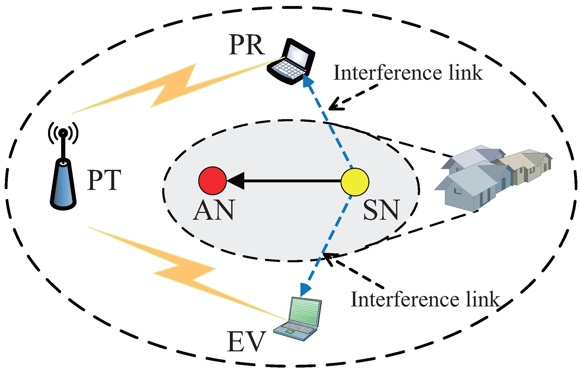
2. System Model
- : the spectrum is idle and detected as idle;
- : the spectrum is occupied and detected as idle;
- : the spectrum is idle and detected as busy;
- :the spectrum is occupied and detected as busy.
3. The Reciprocally-Benefited Secure Transmission Strategy
3.1. Problem Formulation
3.2. Optimal Power Allocation
3.2.1. Equation (31) Has No Root:
3.2.2. Equation (31) Has Two Roots:
- , when , , and .
- , when and .
- , when , , , , , , , and .
- , when , , and .
- , when , , , , , , , , , , and .
4. Performance Analysis
4.1. Further Discussion of the SN’s Transmit Power
- In and , the channel is idle, and the SN will access the licensed spectrum with power and , respectively. Under the average transmit power constraint, and are derived through the optimal water-filling method.
- In and , the SN’s transmission will affect the secrecy outage probability of the primary network. Since the derivation of is similar with , we take for example.
- (1)
- If , the channel quality between the PT and the PR is always worse than the channel quality between the PT and the EV. Under this condition, the primary information security cannot be guaranteed even though the SN optimally allocates its transmit power to interfere with the EV. Therefore, for this case, the SN will access the licensed spectrum with its maximum transmission power as shown in Equation (38).
- (2)
- If , there are six cases, which are shown in Appendix A, and we take and for example.: If , it indicates that the direct transmission channel quality of the primary network is sufficiently good, and the eavesdropper cannot acquire the primary confidential messages even without the assistance of the SN. In this case, the SN will transmit with its maximum power as shown in Equation (38).: If , it indicates that the channel quality between the PT and the PR is neither sufficiently better nor worse than the channel quality between the PT and the EV. In this scenario, the tradeoff between the CRSN’s performance and the primary secrecy outage probability constraint needs to be studied. Set and . Suppose . Obviously, if the CRSN refuses the cooperation request from the PT, the CRSN can acquire the maximum transmission rate. We can denote μ as the cost that the CRSN has to pay if the secrecy outage probability of the primary network is caused. If , the CRSN will transmit with a large power ℓ to maximize its own performance and, thus, causes a primary secrecy outage because the CRSN only needs to pay a relatively small cost. However, if , the CRSN will use a low power to guarantee the secure transmission of the primary network since the cost due to the secrecy outage is large. Therefore, the performance tradeoff between the transmission rate of the CRSN and the secrecy outage probability of primary network can be acquired.
4.2. Asymptotic Secrecy Rate Analysis
4.2.1.
4.2.2.
- , .
- , there are two roots, which are denoted as and . Set . Since is a monotonically-increasing function with respect to and , . Then, if , the optimal power is one value of zero, , and that can maximize the function . Otherwise, the optimal power is .
4.3. The Outage Probability Analysis of the CRSN
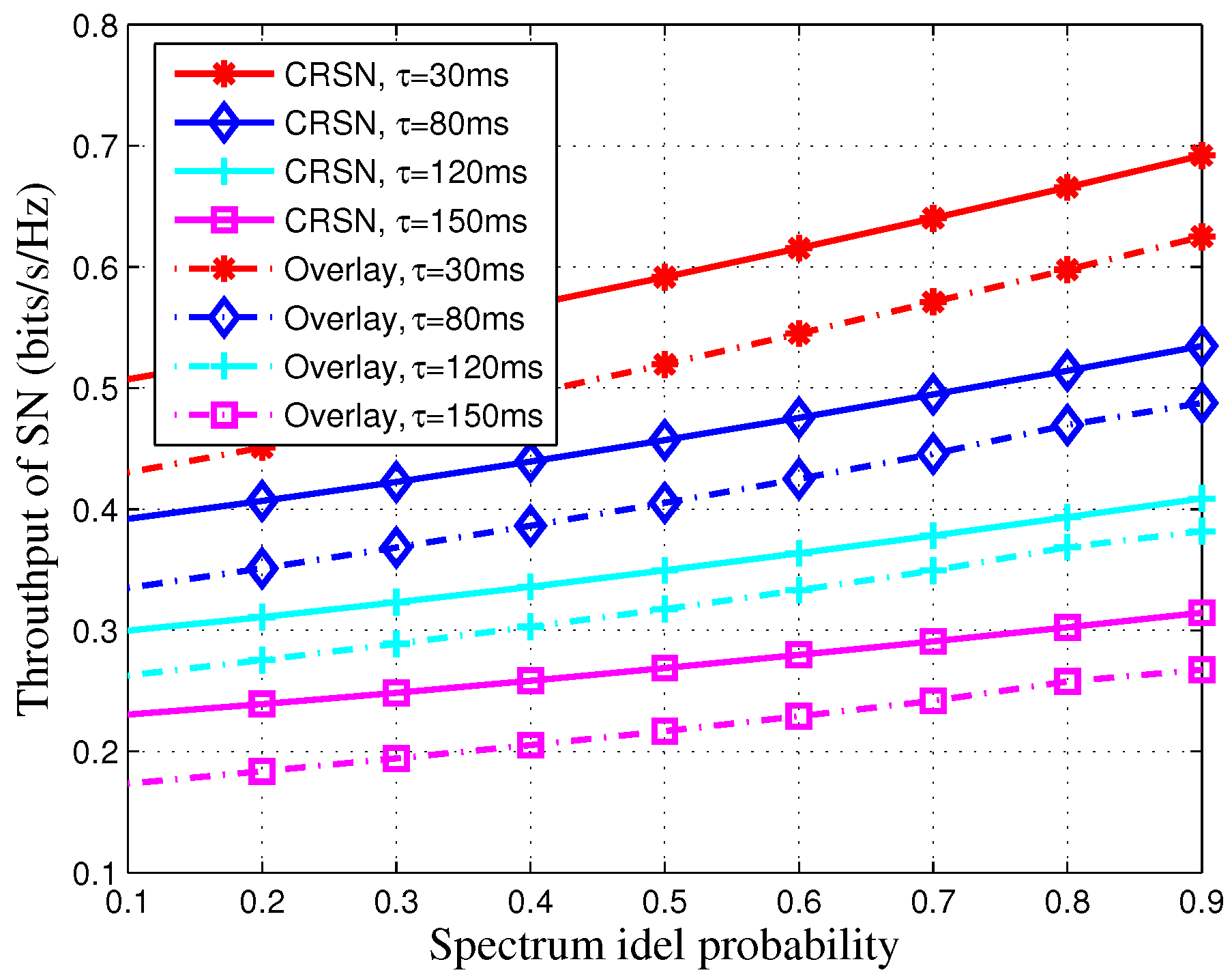
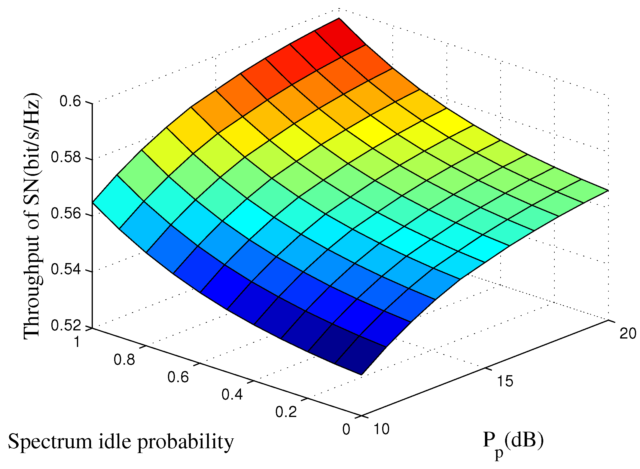
5. Simulation Results
6. Conclusions
Acknowledgments
Author Contributions
Conflicts of Interest
Appendix A. The Derivation Process of
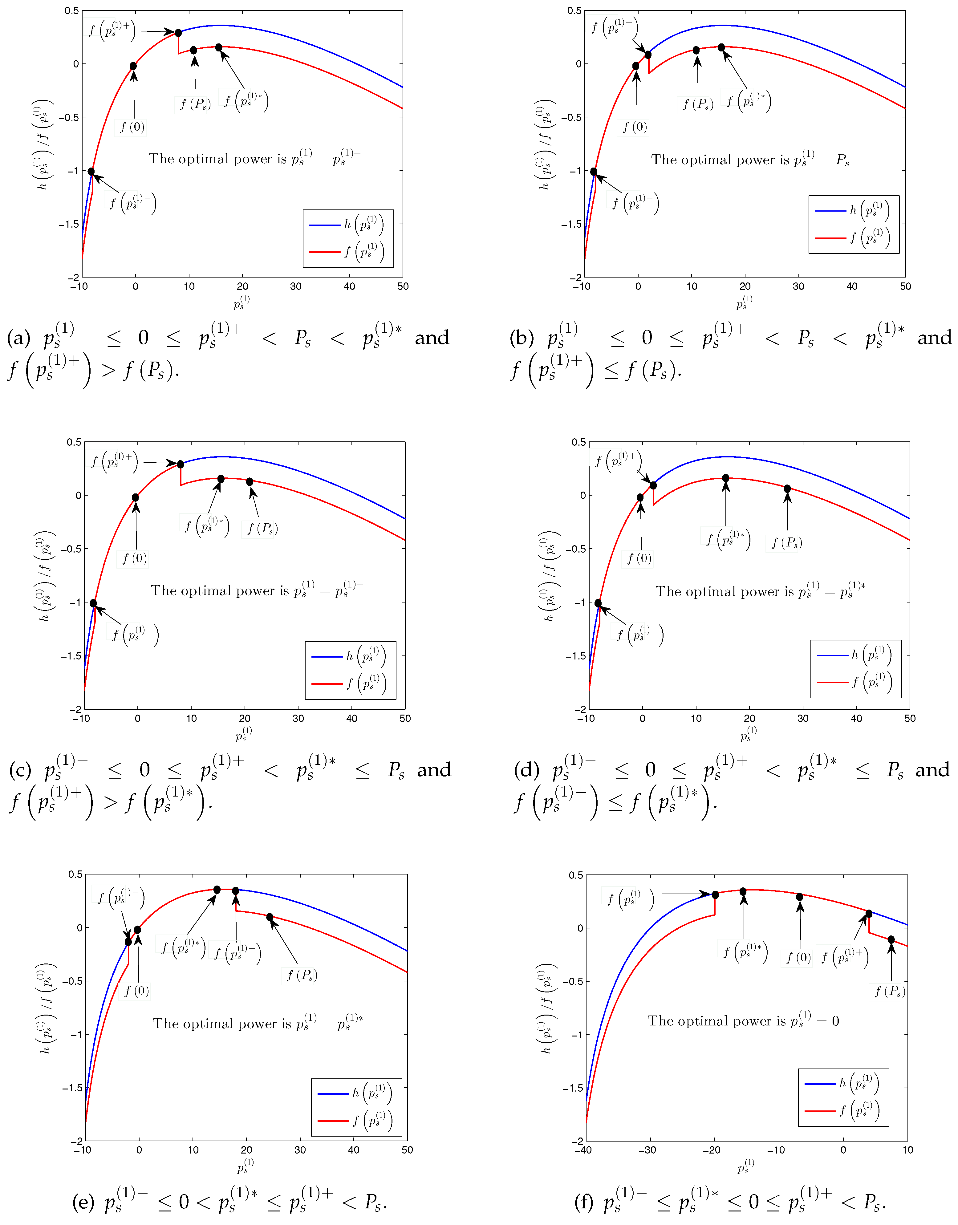
- : If and , the optimal transmit power is , which is shown in Figure A1a. Otherwise, if , the optimal transmit power is , which is shown in Figure A1b. If and , the optimal transmit power is , which is shown in Figure A1c. Otherwise, if , the optimal transmit power is , which is shown in Figure A1d. If , the optimal transmit power is , which is shown in Figure A1e. If , the optimal transmit power is , which is shown in Figure A1f.
- : If or , the optimal transmit power is . If , the optimal transmit power is . If , the optimal transmit power is .
- : If or , the optimal transmit power is . If , the optimal transmit power is . If and , the optimal transmit power is . Otherwise, if , the optimal transmit power is .
- : If and , the optimal transmit power is . Otherwise, if , the optimal transmit power is . If and , the optimal transmit power is . Otherwise, if , the optimal transmit power is . If , the optimal transmit power is . If and , the optimal transmit power is . Otherwise, if , the optimal transmit power is .
- : If , the optimal transmit power is . If , the optimal transmit power is . If or , the optimal transmit power is .
- : If , or , the optimal transmit power is . If , the optimal transmit power is .
References
- Oliveira, L.M.L.; Rodrigues, J.J.P.C. Wireless sensor networks: A survey on environmental monitoring. J. Commun. 2011, 6, 143–151. [Google Scholar] [CrossRef]
- Shen, H.; Li, Z.; Qin, C. Efficient data collection for large-scal mobile monitoring applications. IEEE Trans. Parallel Distrib. Syst. 2014, 25, 1424–1436. [Google Scholar] [CrossRef]
- Langhammer, N.; Kays, R. Performance evaluation of wireless home automation networks in indoor scenarios. IEEE Trans. Smart Grid 2012, 3, 2252–2261. [Google Scholar] [CrossRef]
- Suryadevara, N.K.; Mukhopadhyay, S.C.; Kelly, S.D.T.; Gill, S.P.S. WSN-based smart sensors and actuator for power management in intelligent buildings. IEEE/ASME Trans. Mechatron. 2015, 20, 564–571. [Google Scholar] [CrossRef]
- Akyildiz, I.F.; Su, W.; Sankarasubramaniam, Y.; Cayirci, E. A survey on sensor networks. IEEE Commun. Mag. 2002, 40, 101–114. [Google Scholar] [CrossRef]
- Chiara, B.; Andrea, C.; Davide, D.; Roberto, V. An overview on wireless sensor networks technology and evolution. Sensors 2009, 9, 6869–6896. [Google Scholar]
- Baker, S.D.; King, S.W.; Welch, J.P. Performance measures of ISM-band and conventional telemetry. IEEE Eng. Med. Biol. Mag. 2004, 23, 27–36. [Google Scholar] [CrossRef] [PubMed]
- Mitola, J.; Maguire, G.Q. Cognitive radio: Making software radios more personal. IEEE Pers. Commun. 1999, 6, 13–18. [Google Scholar] [CrossRef]
- Zhang, W.; Mallik, R.K.; Letaief, K. Optimization of cooperative spectrum sensing with energy detection in cognitive radio networks. IEEE Trans. Wirel. Commun. 2009, 8, 5761–5766. [Google Scholar] [CrossRef]
- Liang, Y.C.; Zeng, Y.; Peh, E.C.Y.; Hoang, A.T. Sensing-throughput tradeoff for cognitive radio networks. IEEE Trans. Wirel. Commun. 2008, 7, 1326–1337. [Google Scholar] [CrossRef]
- Akan, O.B.; Karli, O.B.; Ergul, O. Cognitive radio sensor networks. IEEE Netw. 2009, 23, 3369–3380. [Google Scholar] [CrossRef]
- Asokan, A.; Ayyappadas, R. Survey on cognitive radio and cognitive radio sensor networks. In Proceedings of the 21st IEEE International Conference on Electronics Circuits and Systems (ICECS-2014), Marseille, France, 7–10 December 2014; pp. 1–7.
- Deng, R.; Chen, J.; Yen, C.; Cheng, P.; Sun, Y. Energy-efficient cooperative spectrum sensing by optimal scheduling in sensor-aided cognitive radio networks. IEEE Trans. Veh. Technol. 2012, 61, 716–725. [Google Scholar] [CrossRef]
- Han, J.A.; Jeon, W.S.; Jeong, D.G. Energy-efficient channel management scheme for cognitive radio sensor networks. IEEE Trans. Veh. Technol. 2011, 60, 1905–1920. [Google Scholar] [CrossRef]
- Jamal, A.; Than, C.K.; Wong, W.C. CR-WSN MAC: An energy efficient and spectrum aware MAC protocol for cognitive radio sensor network. In Proceedings of the 9th International Conference on Cognitive Radio Oriented Wireless Networks, Oulu, Finland, 2–4 June 2014; pp. 67–72.
- Liang, Z.; Feng, S.; Zhao, D.; Shen, X. Delay performance analysis for supporting real-time traffic in a cognitive radio sensor network. IEEE Trans. Wirel. Commun. 2011, 10, 325–335. [Google Scholar] [CrossRef]
- Chen, Y.; Woo, W.L.; Wang, C.X. Channel modeling of information transmission over cognitive interrogator-sensor networks. IEEE Trans. Veh. Technol. 2011, 60, 2–15. [Google Scholar] [CrossRef]
- Lin, S.C.; Chen, K.C. Improving spectrum efficiency via in-network computations in cognitive radio sensor networks. IEEE Trans. Wirel. Commun. 2014, 13, 1222–1234. [Google Scholar] [CrossRef]
- Gulbahar, B.; Akan, O.B. Information theoretical optimization gains in energy adaptive data gathering and relaying in cognitive radio sensor networks. IEEE Trans. Wirel. Commun. 2012, 11, 1788–1797. [Google Scholar] [CrossRef]
- Wyner, A.D. The wirThe wire-tap channel. Bell Syst. Tech. J. 1975, 54, 1355–1387. [Google Scholar] [CrossRef]
- Zou, Y.; Zhu, J.; Yang, L.; Liang, Y.C.; Yao, Y.D. Securing physical-layer communications for cognitive radio networks. IEEE Commun. Mag. 2015, 53, 1788–1797. [Google Scholar] [CrossRef]
- Yang, J.; Kim, I.M.; Kim, D.I. Power-constrained optimal cooperative jamming for multiuser broadcast channel. IEEE Wirel. Commun. Lett. 2013, 2, 411–414. [Google Scholar] [CrossRef]
- Sun, L.; Ren, P.; Du, Q.; Wang, Y.; Gao, Z. Security-aware relaying scheme for cooperative networks with untrusted relay nodes. IEEE Commun. Lett. 2015, 19, 463–466. [Google Scholar] [CrossRef]
- Xu, Q.; Ren, P.; Du, Q.; Sun, L. Secure Secondary Communications with Curious Primary Users in Cognitive Underlay Networks. In Proceedings of the IEEE Vehicular Technology Conference (VTC-Spring), Nanjing, China, 15–18 May 2016; pp. 1–5.
- Park, K.H.; Wang, T.; Alouini, M.S. On the jamming power allocation for secure amplify-and-forward relaying via cooperative jamming. IEEE J. Sel. Areas Commun. 2013, 31, 1741–1751. [Google Scholar] [CrossRef]
- Liau, Q.Y.; Leow, C.Y.; Ding, Z. Physical layer security rsing two-path successive relaying. Sensors 2016, 16, 846. [Google Scholar] [CrossRef] [PubMed]
- Bassily, R.; Ulukus, S. Deaf cooperative and relay selection strategies for secure communication in multiple relay networks. IEEE Trans. Signal Process. 2013, 61, 1544–1554. [Google Scholar] [CrossRef]
- Mokari, N.; Parsaeefard, S.; Saeedi, H.; Azmi, P. Cooperative seure resource allocation in cognitive radio networks with guaranteed secrecy rate for primary users. IEEE Trans. Wirel. Commun. 2014, 13, 1058–1073. [Google Scholar] [CrossRef]
- Zhang, N.; Lu, N.; Cheng, N.; Mark, J.W.; Shen, X. Cooperative sepctrum access towards secure information transfer for CRN. IEEE J. Sel. Areas Commun. 2013, 31, 2453–2464. [Google Scholar] [CrossRef]
- Stanojev, I.; Yener, A. Improving secrecy rate via spectrum leasing for friendly jamming. IEEE Trans. Wirel. Commun. 2013, 12, 134–145. [Google Scholar] [CrossRef]
- Dong, L.; Han, Z.; Petropulu, A.P.; Poor, H.V. Improving wireless physical layer security via cooperating relays. IEEE Trans. Signal Process. 2010, 58, 1875–1888. [Google Scholar] [CrossRef]
- Li, J.; Petropulu, A.P.; Weber, S. On cooperative relaying schemes for wireless physical layer security. IEEE Trans. Signal Process. 2011, 59, 4985–4996. [Google Scholar] [CrossRef]
- Yang, Y.; Li, Q.; Ma, W.; Ge, J.; Ching, P.C. Cooperative secure beamforming for AF relay networks with multiple eavesdroppers. IEEE Signal Process. Lett. 2013, 20, 35–38. [Google Scholar] [CrossRef]
- Wang, H.-M.; Luo, M.; Yin, Q.; Xia, X.-G. Hybrid cooperative beamforming and jamming for physical-layer security of two-way relay networks. IEEE Trans. Inf. Forensics Secur. 2013, 8, 2007–2020. [Google Scholar] [CrossRef]
- Fakoorian, S.A.A.; Swindlehurst, A.L. Solutions for the MIMO Gaussian wiretap channel with a cooperative jammer. IEEE Trans. Signal Process. 2011, 59, 5013–5022. [Google Scholar] [CrossRef]
- Zhang, R.; Song, L.; Han, Z.; Jiao, B. Physical layer security for two-way untrusted relaying with friendly jammers. IEEE Trans. Veh. Technol. 2012, 61, 3693–3704. [Google Scholar] [CrossRef]
- Sun, L.; Zhang, T.; Li, Y.; Niu, H. Performance study of two-hop amplify-and-forward systems with untrustworthy relay nodes. IEEE Trans. Veh. Technol. 2012, 61, 3801–3807. [Google Scholar] [CrossRef]
- Gopala, P.K.; Lai, L.; Gamal, H.E. On the secrecy capacity of fading channels. IEEE Trans. Inf. Theory 2008, 54, 4686–4698. [Google Scholar] [CrossRef]
- Chorti, A.; Perlaza, S.M.; Han, Z.; Poor, H.V. On the resilience of wireless multiuser networks to passive and active eavesdroppers. IEEE J. Sel. Areas Commun. 2012, 31, 1850–1863. [Google Scholar] [CrossRef]
- Zhou, X.; Maham, B.; Hjorunges, A. Pilot contamination for active eavesdropping. IEEE Trans. Wirel. Commun. 2012, 11, 903–907. [Google Scholar] [CrossRef]
- Mukherjee, A.; Swindlehurst, A.L. Detecting passive eavesdroppers in the MIMO wiretap channel. In Proceedings of the 2012 IEEE International Conference on Acoustics, Speech and Signal Processing (ICASSP 2012), Kyoto, Japan, 25–30 March 2012; pp. 2809–2812.
- Wang, Y.; Ren, P.; Gao, F.; Su, Z. A hybrid underlay/overlay transmission mode for cognitive radio netwroks with statistical quality-of-service provisioning. IEEE Trans. Wirel. Commun. 2014, 13, 1482–1498. [Google Scholar] [CrossRef]
- Wang, Y.; Ren, P.; Du, Q.; Zhang, C. Optimal resource allocation for spectrum sensing based cognitive radio networks with statistical QoS guarantees. Mobile Netw. Appl. 2012, 17, 711–720. [Google Scholar] [CrossRef]
- Fanous, A.; Ephremides, A. Ephremides, Access schemes for mitigating the effects of sensing errors in cognitive wireless netowrks. IEEE Trans. Wirel. Commun. 2014, 13, 3343–3352. [Google Scholar] [CrossRef]
- Shafie, A.E. Cognitive access protocol for alleviating sensing errors in cognitive multiple-access systems. IEEE Wirel. Commun. Lett. 2014, 3, 297–300. [Google Scholar] [CrossRef]
- Boyd, S.; Vandenberghe, L. Vandenberghe, Convex Optimization; Cambridge University Press: London, UK, 2004. [Google Scholar]
- Wang, X.; Berger, T. Spatial channel reuse in wireless sensor networks. Wirel. Netw. 2008, 14, 133–146. [Google Scholar] [CrossRef]
- Lee, W.-Y.; Akyildiz, I.F. Optimal spectrum sensing framework for cognitive radio networks. IEEE Trans. Wirel. Commun. 2008, 7, 3845–3857. [Google Scholar]
- Oto, M.C.; Akan, B. Energy-efficient packet size optimization for cognitive radio sensor networks. IEEE Trans. Wirel. Commun. 2012, 11, 1544–1553. [Google Scholar] [CrossRef]
- Shah, G.A.; Alagoz, F.; Fadel, E.A.; Akan, O.B. A spectrum-aware clustering for efficient multimedia routing in cognitive radio sensor networks. IEEE Trans. Veh. Technol. 2014, 63, 3369–3380. [Google Scholar] [CrossRef]
- Ozger, M.; Fadel, E.; Akan, O.B. Event-to-sink spectrum-aware clustering in mobile cognitive radio sensor networks. IEEE Trans. Mob. Comput. 2016, 15, 2221–2233. [Google Scholar] [CrossRef]


© 2016 by the authors; licensee MDPI, Basel, Switzerland. This article is an open access article distributed under the terms and conditions of the Creative Commons Attribution (CC-BY) license (http://creativecommons.org/licenses/by/4.0/).
Share and Cite
Wang, D.; Ren, P.; Du, Q.; Sun, L.; Wang, Y. Reciprocally-Benefited Secure Transmission for Spectrum Sensing-Based Cognitive Radio Sensor Networks. Sensors 2016, 16, 1998. https://doi.org/10.3390/s16121998
Wang D, Ren P, Du Q, Sun L, Wang Y. Reciprocally-Benefited Secure Transmission for Spectrum Sensing-Based Cognitive Radio Sensor Networks. Sensors. 2016; 16(12):1998. https://doi.org/10.3390/s16121998
Chicago/Turabian StyleWang, Dawei, Pinyi Ren, Qinghe Du, Li Sun, and Yichen Wang. 2016. "Reciprocally-Benefited Secure Transmission for Spectrum Sensing-Based Cognitive Radio Sensor Networks" Sensors 16, no. 12: 1998. https://doi.org/10.3390/s16121998
APA StyleWang, D., Ren, P., Du, Q., Sun, L., & Wang, Y. (2016). Reciprocally-Benefited Secure Transmission for Spectrum Sensing-Based Cognitive Radio Sensor Networks. Sensors, 16(12), 1998. https://doi.org/10.3390/s16121998