
IEEE 802.11ah: A Technology to Face the IoT Challenge


Abstract
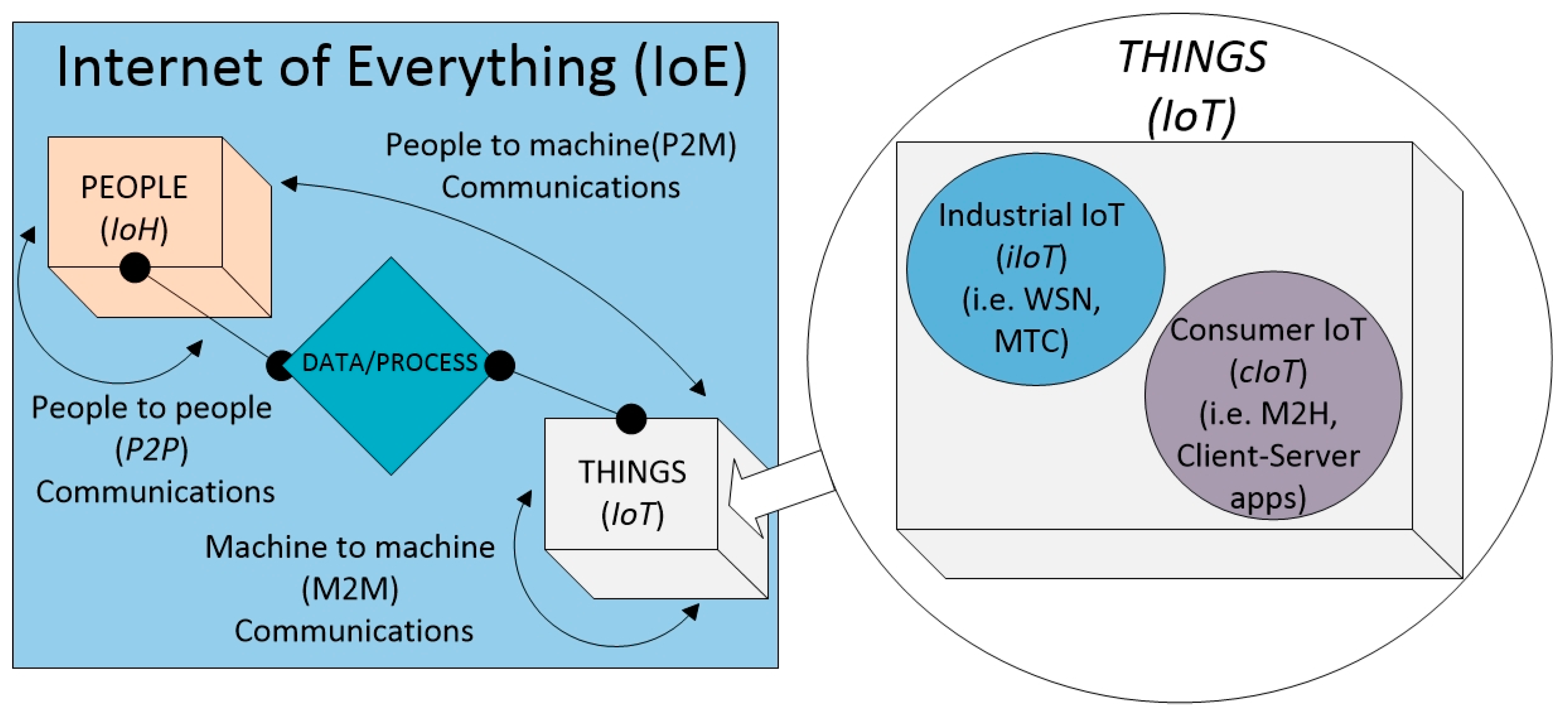
:1. Introduction
- Smart sensors and meters. The goal of the new amendment is to enable IEEE 802.11 technology to cover IoT applications for indoor and outdoor spaces in urban, suburban and rural environments.
- Backhaul aggregation. This is a scenario in which IEEE 802.11ah routers/gateways would gather data from leaf devices (i.e., sensors) and forward information to servers, utilizing IEEE 802.11ah links. This use case is attractive for long range communications.
- Extended range hotspot and cellular offloading. Both high throughput and long transmission range make sub-1 GHz communications very attractive for extending hotspot range and for traffic offloading in mobile networks.
2. Challenges for IoT Applications and IEEE 802.11ah
2.1. Coverage Range
2.2. Time and Frequency Resources
2.3. Supporting a Large Number of IoT Devices
2.4. Low Power Consumption
3. Comparative Analysis of IEEE 802.11ah with Previous IEEE 802.11 Amendments
3.1. Comparison of IEEE 802.11 Amendments Based on MAC Features
3.1.1. Backwards Compatibility
3.1.2. Distributed Channel Access (DCF)
3.1.3. Point Coordinated Function (PCF)
3.1.4. Hybrid Coordination Function (HCF)
- HCF Controlled Channel Access (HCCA)It is similar to PCF and uses the same polling mechanism to assign transmission opportunity to QoS enabled stations.
- Enhanced Distributed Channel Access (EDCA)EDCA is an extension of the DCF mechanism that tries to implement service differentiation by classifying the traffic into different categories with different priorities. In EDCA mode, a traffic class can make itself a higher prioritized traffic class by statistically reducing its transmission delay by declaring an Access Category (AC) that has higher priority for contending shared channel.
3.1.5. Transmission Opportunity (TXOP)
- For IEEE 802.11-2007:TXOP defines a period of time for which a station accessing the channel is allowed to transmit multiple frames without using channel access procedure for all the frames.
- For IEEE 802.11n/ac/ah:In these amendments, the TXOP procedure is enhanced, where the reverse mechanism allows the holder of TXOP to allocate the unused TXOP time to its receiver to enhance the channel utilization and perform reverse direction traffic flows. This mechanism is known as Reverse Direction (RD) protocol.
- For IEEE 802.11ah:IEEE 802.11ah has introduced bi-directional TXOP (BDT) that can help non-AP station (i.e., sensors etc.) to minimize energy consumption. This technique allows the combination of transmission and reception of frames within a single TXOP, where the reduction in the required frame exchange enables stations to extend their battery life time. In addition, this mechanism assists in efficient use of contention based channel accesses.
3.1.6. Response Indication Deferral (RID)
3.1.7. Frame Aggregation:
- For IEEE 802.11n:It employs two steps of accumulation to increase the size of the data frame to be transmitted. The first, which is at the top of the MAC, assembles MAC service data units (MSDU) and is called A-MSDU. Another, at the bottom of the MAC, adds MAC Protocol Data Units (MPDUs) and is called A-MPDU.
- For IEEE 802.11ac/11ah:Enhanced frame aggregation methods are used. All frames follow the A-MPDU format; the maximum size of A-MPDU is increased for IEEE 802.11ac.
3.1.8. Block Acknowledgement (Block ACK)
- For IEEE 802.11n:Block ACK method is modified to support multiple MPDUs in an A-MPDU. The sender only resends the MPDUs that have not been correctly received by the receiver and are not acknowledged by it.
- For IEEE 802.11ah:Block ACK response includes the preferred MCS and the bandwidth information. IEEE 802.11ah also introduces the fragment Block ACK procedure. Fragments obtained from the partition of a MSDU can be acknowledged either using immediate acknowledgement by responding with NDP Block ACK frames, or following the normal Block ACK procedure.
3.1.9. Multi-User (MU) Aggregation
3.1.10. Null Data Packet (NDP)
3.1.11. Group ID
3.1.12. BSS Color
3.1.13. Dynamic Bandwidth Management
3.1.14. Subchannel Selective Transmission (SST)
3.1.15. Traffic Indication Map (TIM)
3.1.16. Target Wake Time (TWT)
3.1.17. Hierarchical AID
3.1.18. Dynamic AID Reassignment
3.1.19. Restricted Access Window (RAW)
3.1.20. Group Sectorization
3.1.21. Relay Operations
3.1.22. Power Saving at AP
3.1.23. Low Power Mode of Operations
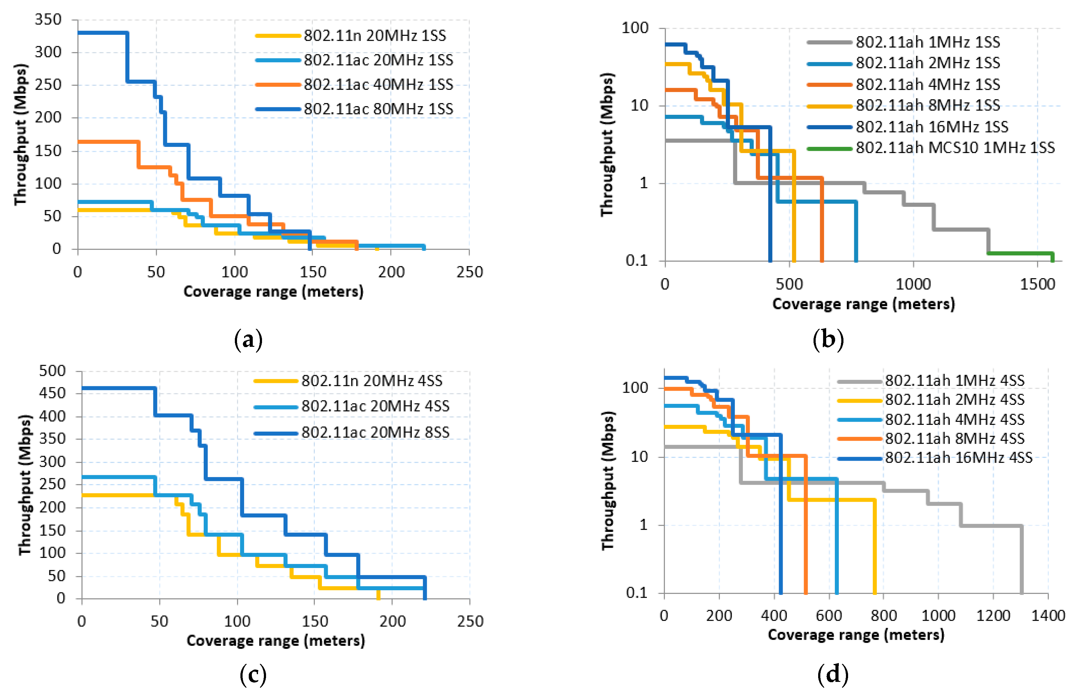
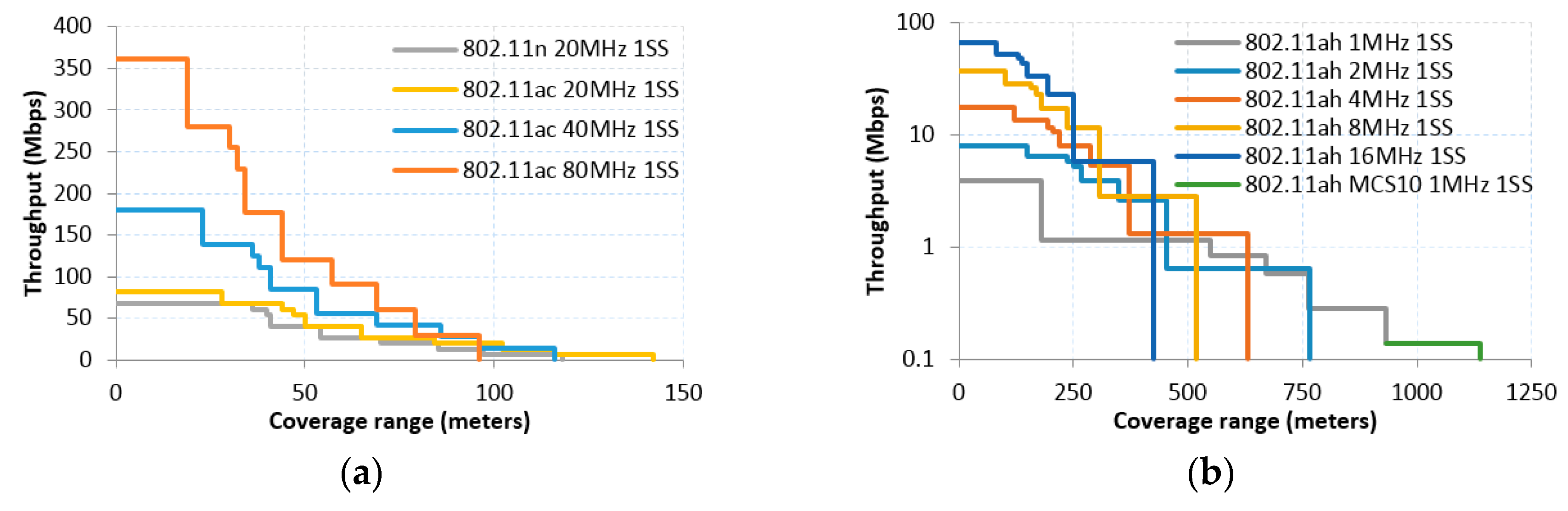
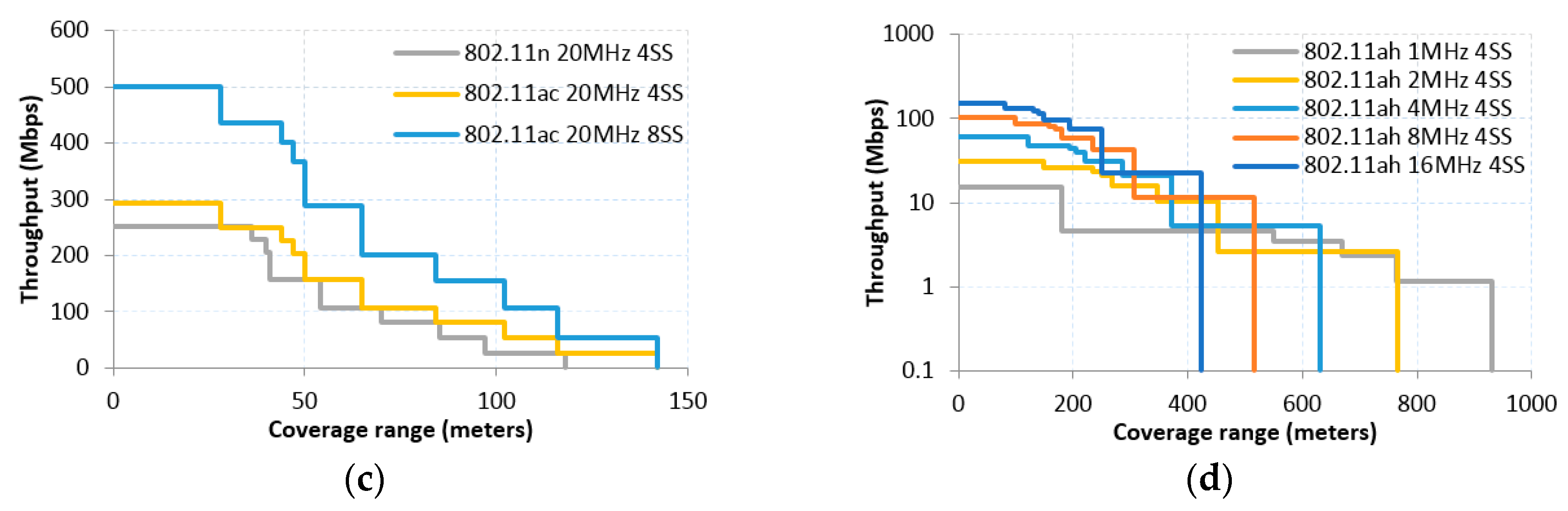
3.2.Throughput and Range Characterization of IEEE 802.11 Amendments
- 1 MHz CBW case with short and long Guard Interval (GI) subcases, following Equations (5) and (6), respectively. Note that with 1 MHz CBW only one PHY preamble/header type applies (cf. Table 3).
- Short preamble case for 2, 4, 8 and 16 MHz CBW with short and long GI subcases, which also follow Equations (5) and (6), respectively; in this case, a different value for the PHY preamble/header length should be used (cf. Table 3).
- Long preamble case for 4, 8 and 16MHz CBW with short and long GI subcases, following Equations (7) and (8), respectively:
4. IoT Applications
Meeting the Requirements of IoT Applications
5. Application and Infrastructure Costs
6. Conclusions
Acknowledgments
Author Contributions
Conflicts of Interest
References
- Khorov, E.; Lyakhov, A.; Krotov, A.; Guschin, A. A survey on IEEE 802.11ah: An enabling networking technology for smart cities. Comput. Commun. 2014, 58, 53–69. [Google Scholar] [CrossRef]
- IEEE P802.11ah/D 9.0 Draft Part 11: Wireless LAN Medium Access Control (MAC) and Physical Layer (PHY) Specifications—Amendment Draft. Available online: http://ieeexplore.ieee.org/document/7558107/ (accessed on 21 November 2016).
- Adame, T.; Bel, A.; Bellalta, B.; Barcelo, J.; Oliver, M. IEEE 802.11AH: The WiFi approach for M2M communications. IEEE Wirel. Commun. 2014, 21, 144–152. [Google Scholar] [CrossRef]
- Aust, S.; Prasad, R.V.; Niemegeers, I.G.M.M. Outdoor Long-Range WLANs: A Lesson for IEEE 802.11ah. IEEE Commun. Surv. Tutor. 2015, 17, 1761–1775. [Google Scholar] [CrossRef]
- Sun, W.; Choi, M.; Choi, S. IEEE 802.11ah: A long range 802.11 WLAN at Sub 1 GHz. J. ICT Stand. 2013, 1, 83–108. [Google Scholar]
- Long Range Low Power (LRLP) Operation in 802.11: Use Cases and Functional Requirements: Guidelines for PAR Development. Available online: https://mentor.ieee.org/802.11/dcn/15/11-15-1446-12-lrlp-lrlp-output-report-draft.docx (accessed on 21 November 2016).
- 11ax Support for IoT. Available online: https://mentor.ieee.org/802.11/dcn/15/11-15-1375-00-00ax-11ax-support-for-iot-requirements-and-technological-implications.pptx (accessed on 21 November 2016).
- Vega, L.F.D.; Robles, M.; Morabito, R. IPv6 over 802.11ah. Available online: https://tools.ietf.org/html/draft-delcarpio-6lo-wlanah-01 (accessed on 21 November 2016).
- Wang, Y.P.E.; Lin, X.; Adhikary, A.; Grövlen, A.; Sui, Y.; Blankenship, Y.; Bergman, J.; Razaghi, H.S. A Primer on 3GPP Narrowband Internet of Things (NB-IoT). arXiv, 2016; arXiv:1606.04171. [Google Scholar]
- Palattella, M.; Dohler, M.; Grieco, A.; Rizzo, G.; Torsner, J.; Engel, T.; Ladid, L. Internet of Things in the 5G Era: Enablers, Architecture and Business Models. IEEE J. Sel. Areas Commun. 2016, 34, 510–527. [Google Scholar] [CrossRef]
- Porat, R. TGah Channel Model. Available online: https://mentor.ieee.org/802.11/dcn/11/11-11-0968-04-00ah-channel-model-text.docx (accessed on 21 November 2016).
- Garcia-Villegas, E. Corrections to TGah Channel Model. Available online: https://mentor.ieee.org/802.11/dcn/15/11-15-0425-00-00ah-corrections-to-tgah-channel-model.pptx (accessed on 21 November 2016).
- Hazmi, A.; Rinne, J.; Valkama, M. Feasibility study of IΕΕΕ 802.11ah radio technology for IoT and M2M use cases. In Proceedings of the 2012 IEEE Globecom Workshops (GC Wkshps), Anaheim, CA, USA, 3–7 December 2012.
- Gomez, C.; Paradells, J. Urban Automation Networks: Current and Emerging Solutions for Sensed Data Collection and Actuation in Smart Cities. Sensors 2015, 15, 22874–22898. [Google Scholar] [CrossRef] [PubMed]
- Kuzlu, M.; Pipattanasomporn, M.; Rahman, S. Communication network requirements for major smart grid applications in HAN, NAN and WAN. Comput. Netw. 2014, 67, 74–88. [Google Scholar] [CrossRef]
- Martinez, I. Contribuciones a Modelos de Tráfico y Control de QoS en los Nuevos Servicios Sanitarios Basados en Telemedicine. Ph.D. Thesis, Aragon Institute of Engineering Research, Zaragoza, Spain, 2006. [Google Scholar]
- Bianchi, G. Performance analysis of the IEEE 802.11 distributed coordination function. IEEE J. Sel. Areas Commun. 2000, 18, 535–547. [Google Scholar] [CrossRef]

| Feature | IEEE 802.11 (n/ac) | IEEE 802.11ah | ZigBee/802.15.4e | BLE | 3GPP MTC | LPWAN | |
|---|---|---|---|---|---|---|---|
| LoRaWAN | SigFox | ||||||
| Frequency band (GHz) | Unlicensed 2.4, 5 GHz | Unlicensed 900 MHz | Unlicensed 868/915 MHz 2.4 GHz | Unlicensed 2.4 GHz | Licensed <5 GHz | Unlicensed 867–928 MHz | Unlicensed 868–902 MHz |
| Data Rate | 6.5–6933 Mbps | 150 kbps–346 Mbps | <250 kbps | <1 Mbps | <1 Mbps | <25 kbps | <1 kbps |
| Coverage range | <200 m | <1.5 km | <100 m | <50 m | <100 km | <20 km | <40 km |
| Power consumption | Medium | Low | Low | Low | Low | Low | Low |
| Number of devices supported | 2007 | 8000 | 65,000 | Unlimited * | >100,000 | >100,000 | >1,000,000 |
| Notable Features | 802.11-2007 | 802.11n | 802.11ac | 802.11ah | |
|---|---|---|---|---|---|
| Backwards compatibility | X | X | X | ||
| DCF | X | ||||
| PCF | X | ||||
| HCF | HCCA | X | X | X | |
| EDCA | X | X | X | X | |
| TXOP | Forward | X | X | X | X |
| RD protocol | X | X | X | ||
| BDT | X | ||||
| RID | X | ||||
| Frame Aggregation | X | X | X | ||
| Block ACK | X | X | X | X | |
| Multi User (MU) Aggregation | X | X | |||
| Null Data Packet (NDP) | X | X | X | ||
| Group-ID | X | X | |||
| BSS color | X | ||||
| Dynamic Bandwidth Management | X | ||||
| Subchannel Selective Transmission | X | ||||
| Traffic Indication Map (TIM) | X | X | X | X | |
| Delivery Traffic Indication Map (DTIM) | X | X | X | ||
| Target Wakeup Time | X | ||||
| Grouping of Stations | X | ||||
| Hierarchical AID | X | ||||
| Dynamic AID reassignment | X | ||||
| Restricted Access Window (RAW) | X | ||||
| Group sectorization | X | ||||
| Relay operations | X | ||||
| Power saving at AP | X | ||||
| Low power mode of operations | X | ||||
| Specification | SIFS (µs) | DIFS (µs) | TPreamble &Header (µs) | MAC&LLC Header Size (Bytes) | Signal Extension (µs) | TSym (µs) | TSlot (µs) | CWmin | CWmax |
|---|---|---|---|---|---|---|---|---|---|
| 802.11ah CBW 1 MHz | 160 | 264 | 560 | 26 (Short) 36 (Long) | n/a | 40 (long GI) 36 (short GI) | 52 | 15 | 1023 |
| 802.11ah Short Preamble CBW 2, 4, 8 and 16 MHz | 160 | 264 | 240 | 26 (Short) 36 (Long) | n/a | 40 (long GI) 36 (short GI) | 52 | 15 | 1023 |
| 802.11ah Long Preamble CBW 2, 4, 8 and 16 MHz | 160 | 264 | 320 | 26 (Short) 36 (Long) | n/a | 40 (long GI) 36 (short GI) | 52 | 15 | 1023 |
| 802.11ac | 16 | 34 | 40 | 36 | n/a | 4 | 9 | 15 | 1023 |
| 802.11n 2.4 GHz | 10 | 28 | 36 | 36 | 6 | 4 | 9 | 15 | 1023 |
| 802.11n 5 GHz | 16 | 34 | 36 | 36 | 0 | 4 | 9 | 15 | 1023 |
| Application | Description | Average Payload Size (Bytes) | Average Aggregate Data Rate (Kbps) | Supported Devices at <1 km (Outdoor) | Supported Devices at <500 m (Outdoor) | Supported Devices at <250 m (Indoor) | |
|---|---|---|---|---|---|---|---|
| Permanent connectivity applications | Home/Building automation | Sensitive delay applications, including services to manage different commodity infrastructure, remote control of industrial facilities, smart cities applications, etc. | 100 | 15–30 | 1250 | 2100 | 2500 |
| On-demand meter reading | 100 | 40–180 | 250 | 1000 | 1200 | ||
| Distribution Automation | 150 | 60–480 | 55 | 300 | 400 | ||
| Electric service prepayment | 50–150 | 30–90 | 725 | 2000 | 2100 | ||
| Service on/off switch | 25 | 5–10 | 1600 | 2400 | 2600 | ||
| Security (sensors, alarms). | 100 | 40–180 | 250 | 1050 | 1150 | ||
| Backhaul/core/metro networks * | 1500 | 240–4100 | 1 | 6 | 17 | ||
| Parking Availability | 100 | 40–180 | 250 | 1050 | 1150 | ||
| Street traffic | 100 | 40–180 | 250 | 1050 | 1150 | ||
| Event-based applications | Multi-interval meter reading | Delay-tolerant where data is collected infrequently (multiple times per day) applications, including all non-critical applications not requiring permanent connectivity such as scheduled reporting of bulk measurements. | 100 | <1 | 4200 | 5000 | 5300 |
| Firmware Updates + | 1500 | 45–250 | 400 | 1800 | 2500 | ||
| Garbage Collection | 100 | <1 | 4200 | 5000 | 5300 | ||
| Lighting Control | 100 | <1 | 4200 | 5000 | 5300 | ||
| Green zone management | 100 | <1 | 4200 | 5000 | 5300 | ||
| Environmental Control | 64 | <1 | 4200 | 5000 | 5300 | ||
| Utility infrastructure | 100 | <1 | 4200 | 5000 | 5300 |
| Application | Description | Average Payload Size (Bytes) | Average Aggregate Data Rate (kbps) | Supported Devices at <1 km | Supported Devices at <500 m | Supported Devices at <250 m | |
|---|---|---|---|---|---|---|---|
| Audio | Audio 1 Codec G723.1 Rate 6.4 kbps | In these applications, a variety of codecs are available depending on the audio quality required. | 100 | 80–600 | 5 | 15 | 30 |
| Audio 2 Codec AMRx Rate 12.2 kbps | 120 | 70–650 | 5 | 20 | 35 | ||
| Video | Video 1 Codec H.264 Rate 500 kbps | In these applications different codecs are needed depending on the quality of the video required. | 1500 | 500–4000 | 1 | 3 | 7 |
| Video 2 * Codec H.264 Rate 8 Mbits/s | 1500 | 8000–25,000 | - | 1 | 3 | ||
| Data | Electronic Health Record (EHR) + | Applications involving the transmission of large files in the context of smart/e-health. | 1000 | 1000–10,000 | 1 | 5 | 10 |
| IMG 1 Low resolution lossless compression, 1024 × 768 px 24 bits/px | 1500 | 450–2000 | 3 | 9 | 12 | ||
| IMG 2 ** High resolution lossless compression, 4096 × 4096 px 24 bits/px | 1500 | 3500–20,000 | 1 | 2 | 6 | ||
| Biometrics | Electroencephalography EEG | Applications where data is collected from the electrical signals in the human body to get representative information in the evolution of vital signs. | 100 | 100–400 | 1 | 2 | 3 |
| Electrocardiography ECG | 50 | 50–300 | 1 | 5 | 10 | ||
| Blood pressure(BP)/Pulse Oximeter (SpO) | 400 | 80–1100 | 25 | 140 | 320 |
© 2016 by the authors; licensee MDPI, Basel, Switzerland. This article is an open access article distributed under the terms and conditions of the Creative Commons Attribution (CC-BY) license (http://creativecommons.org/licenses/by/4.0/).
Share and Cite
Baños-Gonzalez, V.; Afaqui, M.S.; Lopez-Aguilera, E.; Garcia-Villegas, E. IEEE 802.11ah: A Technology to Face the IoT Challenge. Sensors 2016, 16, 1960. https://doi.org/10.3390/s16111960
Baños-Gonzalez V, Afaqui MS, Lopez-Aguilera E, Garcia-Villegas E. IEEE 802.11ah: A Technology to Face the IoT Challenge. Sensors. 2016; 16(11):1960. https://doi.org/10.3390/s16111960
Chicago/Turabian StyleBaños-Gonzalez, Victor, M. Shahwaiz Afaqui, Elena Lopez-Aguilera, and Eduard Garcia-Villegas. 2016. "IEEE 802.11ah: A Technology to Face the IoT Challenge" Sensors 16, no. 11: 1960. https://doi.org/10.3390/s16111960
APA StyleBaños-Gonzalez, V., Afaqui, M. S., Lopez-Aguilera, E., & Garcia-Villegas, E. (2016). IEEE 802.11ah: A Technology to Face the IoT Challenge. Sensors, 16(11), 1960. https://doi.org/10.3390/s16111960