Article

In Vivo Neural Recording and Electrochemical Performance of Microelectrode Arrays Modified by Rough-Surfaced AuPt Alloy Nanoparticles with Nanoporosity

1
Key Laboratory of Biomedical Information Engineering of the Ministry of Education, Institute of Biomedical Engineering, School of Life Science and Technology, Xi’an Jiaotong University, Xi’an 710049, China
2
National Engineering Research Center of Health Care and Medical Devices, Xi’an Jiaotong University Branch, Xi’an 710049, China
*
Author to whom correspondence should be addressed.
Sensors 2016, 16(11), 1851; https://doi.org/10.3390/s16111851
Submission received: 10 September 2016 / Revised: 18 October 2016 / Accepted: 28 October 2016 / Published: 3 November 2016

Abstract

:
In order to reduce the impedance and improve in vivo neural recording performance of our developed Michigan type silicon electrodes, rough-surfaced AuPt alloy nanoparticles with nanoporosity were deposited on gold microelectrode sites through electro-co-deposition of Au-Pt-Cu alloy nanoparticles, followed by chemical dealloying Cu. The AuPt alloy nanoparticles modified gold microelectrode sites were characterized by scanning electron microscopy (SEM), electrochemical impedance spectroscopy (EIS), cyclic voltammetry (CV) and in vivo neural recording experiment. The SEM images showed that the prepared AuPt alloy nanoparticles exhibited cauliflower-like shapes and possessed very rough surfaces with many different sizes of pores. Average impedance of rough-surfaced AuPt alloy nanoparticles modified sites was 0.23 MΩ at 1 kHz, which was only 4.7% of that of bare gold microelectrode sites (4.9 MΩ), and corresponding in vitro background noise in the range of 1 Hz to 7500 Hz decreased to 7.5 μ V rms from 34.1 μ V rms at bare gold microelectrode sites. Spontaneous spike signal recording was used to evaluate in vivo neural recording performance of modified microelectrode sites, and results showed that rough-surfaced AuPt alloy nanoparticles modified microelectrode sites exhibited higher average spike signal-to-noise ratio (SNR) of 4.8 in lateral globus pallidus (GPe) due to lower background noise compared to control microelectrodes. Electro-co-deposition of Au-Pt-Cu alloy nanoparticles combined with chemical dealloying Cu was a convenient way for increasing the effective surface area of microelectrode sites, which could reduce electrode impedance and improve the quality of in vivo spike signal recording.

1. Introduction

In vivo neural recording provides a useful method for neuroscientists to understand the basic organization and operation of the nervous system, and especially the electrophysiological changes caused by neurological disorders such as Parkinson’s disease [1,2,3,4,5] and Alzheimer’s disease [6]. Although microwire-based electrodes have been a versatile tool for neuroscientists for decades, the limitations of microwire-based electrodes, such as difficult implantation, low spatial resolution, low reproducibility and manual construction are also well known [7,8]. The rapid development of micro-electro-mechanical systems (MEMS) technology in the biomedical field provides a feasible solution for the above-mentioned problems. With MEMS technology, the precise definition of electrode size and shape can be realized, and multiple recording/stimulation sites can be fabricated on a single probe shank [9]. Starting with the pioneering work from Wise et al. [10], a growing number of silicon-based electrode arrays have been developed in the past and the performances of MEMS silicon microelectrodes have been improved in many aspects [11,12], e.g., three-dimensional arrays [13,14,15], dual-sided microelectrode arrays [16], integrated electronics or microfluidic channels [17,18,19,20,21,22], silicon probes for optical stimulation and imaging [23,24,25,26,27,28] or neurochemical signals detection [29,30,31]. In addition, one of the most important fabrication advancements is to integrate a greater number of recording sites on a single probe shank and simultaneously minimizing the probe geometry to avoid large tissue damages during the insertion. For example, Du et al. [32] designed and developed a high-density silicon-based neural probe employing 64-channel recording sites for performing large-scale, high-density electrophysiology in small, freely behaving animals. However, an inevitable consequence of reducing electrode size is that it will increase the electrode impedance, which introduces high Johnson noise during in vivo neural recording and therefore lowers the quality of recorded neural signals [33,34,35].
In order to solve the above-mentioned problems, many techniques have been proposed, and the most commonly used strategy is to modify small electrode sites with nanostructured materials, which greatly increase the surface area of electrode sites without increasing the size of electrode. In recent years, various nanomaterials have been used to reduce impedance of electrode sites, for example, Desai et al. [36] modified microwire multi-electrode arrays with platinum black to reduce electrode impedance and improve its in vivo neural recording performance. Keefer et al. [37] and Castagnola et al. [38] applied carbon nanotube to enhance neural recording. Other materials, such as iridium oxide [39,40], conducting polymers [41,42,43,44,45,46], gold nanoparticles [47,48], and nanocomposites [49,50,51,52,53] have also been applied to modify electrode sites. With the rapid development of material science, it is believed that more and more nanomaterials will be applied in this field.
In recent years, Au-Pt bimetallic nanoparticles have gained significant research attention and have been widely applied in a variety of fields, such as electrochemical sensors [54,55,56,57], fuel cells [58,59], and Raman scattering [60]. Compared with the corresponding monometallic nanoparticles (Au or Pt nanoparticles), Au-Pt bimetallic nanoparticles possess many favorable characteristics including increased surface area, improved electron transfer rate, enhanced electrocatalytic activity and promoted stability, which mainly result from the synergistic effects of these two monometallic nanoparticles. Recently, Kim et al. [61] electrochemically deposited Au-Pt bimetallic nanoparticles on gold multi-electrode arrays to improve its in vitro neuronal recording performance. However, it is well known that the surface morphology of nanoparticles plays a key role in their properties, and nanoparticles with different surface morphologies may possess different electrochemical characteristics [62]. In addition, electrochemical synthesis method has been widely used to prepare different kinds of metal nanoparticles due to its many advantages including simple synthesis and easily controlling the shape and size of nanoparticles [63]. Chemical dealloying method is often used to create nanoporous metals with tailored porosity [64,65]; for example, Kim et al. [66] applied porous Au films that were prepared via electro-deposition of Ag-Au alloy films followed by chemical dealloying of Ag to modify multi-electrode arrays for in vitro extracellular recording and stimulation. However, to the best of our knowledge, there is no report about the application of rough-surfaced AuPt alloy nanoparticles with nanoporosity prepared via electro-co-deposition of Au-Pt-Cu alloy nanoparticles followed by chemical dealloying Cu to modify gold neural microelectrode arrays.
In this paper, in order to improve the in vivo neural recording performance of our fabricated Michigan type silicon electrodes [67], we modified the round-shaped gold microelectrode sites (diameter of 20 μm) via electro-co-deposition of Au-Pt-Cu alloy nanoparticles followed by chemical dealloying Cu for the first time. Firstly, the prepared rough-surfaced Au-Pt alloy nanoparticles were characterized by scanning electron microscopy (SEM) and X-ray diffraction (XRD), which showed that the prepared AuPt alloy nanoparticles exhibited cauliflower-like shapes and possessed very rough surfaces with many different sizes of pores. Secondly, electrochemical impedance spectroscopy (EIS) was used to evaluate the impedance of modified microelectrode sites and results indicated that average impedance of rough-surfaced AuPt alloy nanoparticles modified sites was 0.23 MΩ at 1 kHz, which was only 4.7% of that of bare gold microelectrode sites (4.9 MΩ). Finally, thermal noises and in vivo spike recording performance of the microelectrode sites modified with rough-surfaced Au-Pt alloy nanoparticles were studied in details.

2. Materials and Methods

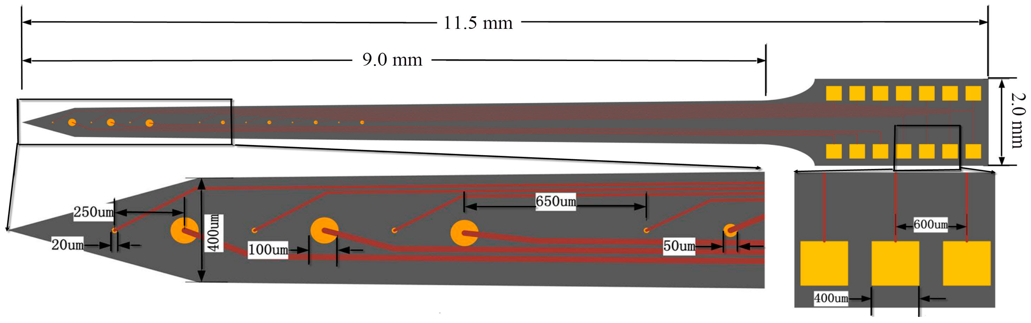
2.1. The Fabricated Microelectrode Arrays

The fabricated microelectrode array with dimensions of 9 mm × 400 μm × 200 μm (length × width × thickness) employed 14 round-shaped gold microelectrode sites distributed on each side. These sites could be divided into three types: three stimulating sites (diameter of 100 μm), seven electrophysiological recording sites (diameter of 20 μm) and four sites with diameter of 50 μm used for neurotransmitter measurements in future work. At the front of the designed microelectrode, three stimulating sites and three recording sites were mutually spaced with equal center-to-center distance of 250 μm. These four sites with diameter of 50 μm and the other four recording sites were also mutually spaced with equal center-to-center distance of 250 μm. Figure 1 showed the schematic diagram of the designed microelectrode array, and design and fabrication of the probes have been described in detail elsewhere [67]. In this paper, the in vivo neural recording and electrochemical performance of recording sites modified by rough-surfaced AuPt alloy nanoparticles were mainly studied. As for stimulating sites, their stimulating performance will be studied in future work.

2.2. Materials and Reagents

Chloroauric acid tetrahydrate (HAuCl4·4H2O) and chloroplatinic acid hexahydrate (H2PtCl6·6H2O) were purchased from Sangon Biotech. Co., Ltd. (Shanghai, China) and Aladdin Industrial Inc. (Shanghai, China), respectively. All other reagents were directly used without further purification. All aqueous solutions were prepared using ultrapure water (Millipore, ≥18 MΩ·cm, Billerica, MA, USA). The phosphate buffer solution (PBS, 0.1 mol/L) was prepared using 0.1 mol/L Na2HPO4 and 0.1 mol/L NaH2PO4 and the pH value of PBS was adjusted by mixing the stock solutions of NaH2PO4 and Na2HPO4 at different ratios.

2.3. Preparation of Rough-Surfaced Aupt Alloy Nanoparticles with Nanoporosity

Prior to preparation, the microelectrode arrays were sonicated in ethanol (1:1), HNO3 (1:1) and ultrapure water in sequence, and finally dried in air. Electrochemical co-deposition of Au-Pt-Cu alloy nanoparticles was carried out at room temperature in a conventional three-electrode electrochemical cell, which was composed of a gold recording site (diameter of 20 μm) of the microelectrode array as the working electrode, a platinum wire as the auxiliary electrode, and an Ag/AgCl (3 M KCl) as the reference electrode. Electrochemical co-deposition was performed at −0.25 V for about 600 s in 0.5 M H2SO4 solution containing 0.5 mM HAuCl4, 0.5 mM H2PtCl6 and 0.25 mM CuSO4. To get the rough-surfaced AuPt alloy nanoparticles with nanoporosity, the Cu was selectively dealloyed in 60% HNO3 at 70 °C for about one hour [64]. After dealloying, the microelectrode arrays were rinsed thoroughly with ultrapure water. For comparison, Au nanoparticles (AuNPs) modified gold recording sites via electrochemical deposition were prepared and used as a control along with the rough-surfaced AuPt alloy nanoparticles modified electrode sites.

2.4. Electrochemical and Physical Characterization

Electrochemical characterization of the microelectrode arrays were analyzed with the CHI 650E electrochemical analyzer (CH Instruments, Shanghai, China) at room temperature in a conventional three-electrode electrochemical cell, which was composed of a fabricated microelectrode array as the working electrode, a platinum wire as the auxiliary electrode, and an Ag/AgCl as the reference electrode. The electrochemical impedance spectroscopy (EIS) was performed in 0.1 M phosphate buffer solution (PBS) at an amplitude of 50 mV and frequencies between 1 Hz and 100 kHz.
Scanning electron microscopic images were collected on a Jsm-7800f field emission scanning electron microscopy (Electro Co., Tokyo, Japan). X-ray diffraction (XRD) patterns were carried out on an X’PertProPANalytical diffractometer using Cu Kα radiation (λ = 0.15418 nm).

2.5. In Vitro Background Noise Measurements

Background noise was measured to evaluate the relationship between electrode impedance and noise level. The background noise measurements were carried out in 0.9% NaCl solution and the background noise referenced to ground was recorded in a Faraday cage. The noise signals were recorded using a Cerebus multi-channel data acquisition system (Blackrock Microsystems, Salt Lake City, UT, USA) and then were filtered by a bandpass ranging from 1 Hz to 7.5 kHz and digitized (sampling rate: 30 kHz) for offline analysis. The noise signals were shown in time and frequency domains. Noise power spectra with frequency range of 1 to 1000 Hz were presented.

2.6. In Vivo Neural Recording and Data Analysis

In vivo neural recordings in the brain of the anesthetized rats were performed to compare the performance of recording spontaneous discharge signals at AuNPs and rough-surfaced AuPt alloy nanoparticles modified electrode sites. Male Sprague-Dawley (SD) rats weighing 250–300 g (Laboratory Animal Center at Xi’an Jiaotong University School of Medicine) were used in the electrophysiological experiments. All animal experiments were conducted in accordance with protocols approved by animal ethics committee of Xi’an Jiaotong University. The SD rats were anesthetized using an intraperitoneal injection of 2% pelltobarbitalum natricum solution (0.4 mL/100 g). After craniotomy and resection of the dura mater, the cortical surface was exposed.
For spike signals recording, the microelectrode array was implanted into lateral globus pallidus (GPe, AP: 1.4, ML: 3.4, DV: 5.5–6.5) of SD rat. Original signals were recorded at a sampling rate of 30 kHz and the recorded neural signals were filtered by a bandpass ranging from 500 Hz to 5 kHz to get the spike signals. Spike signals were analyzed offline using custom-automated MatLab (Mathworks Inc., Natick, MA, USA) software. The offline spike detection threshold is set at 5 σ , where   σ is defined as [68]:
σ   =   median { | spike   signals | 0 . 6745 }
Note that taking a threshold based on the standard deviation of the signal (including the spikes) could lead to unreliable values, especially in cases with high firing rates and large spike amplitudes. In contrast, by using the threshold based on the median, the interference of the spikes is diminished [68]. The signal-to-noise ratio (SNR) was calculated as the root-mean-square (rms) of a spike divided by the standard deviation of the raw spike data trace [69].

3. Results and Discussion

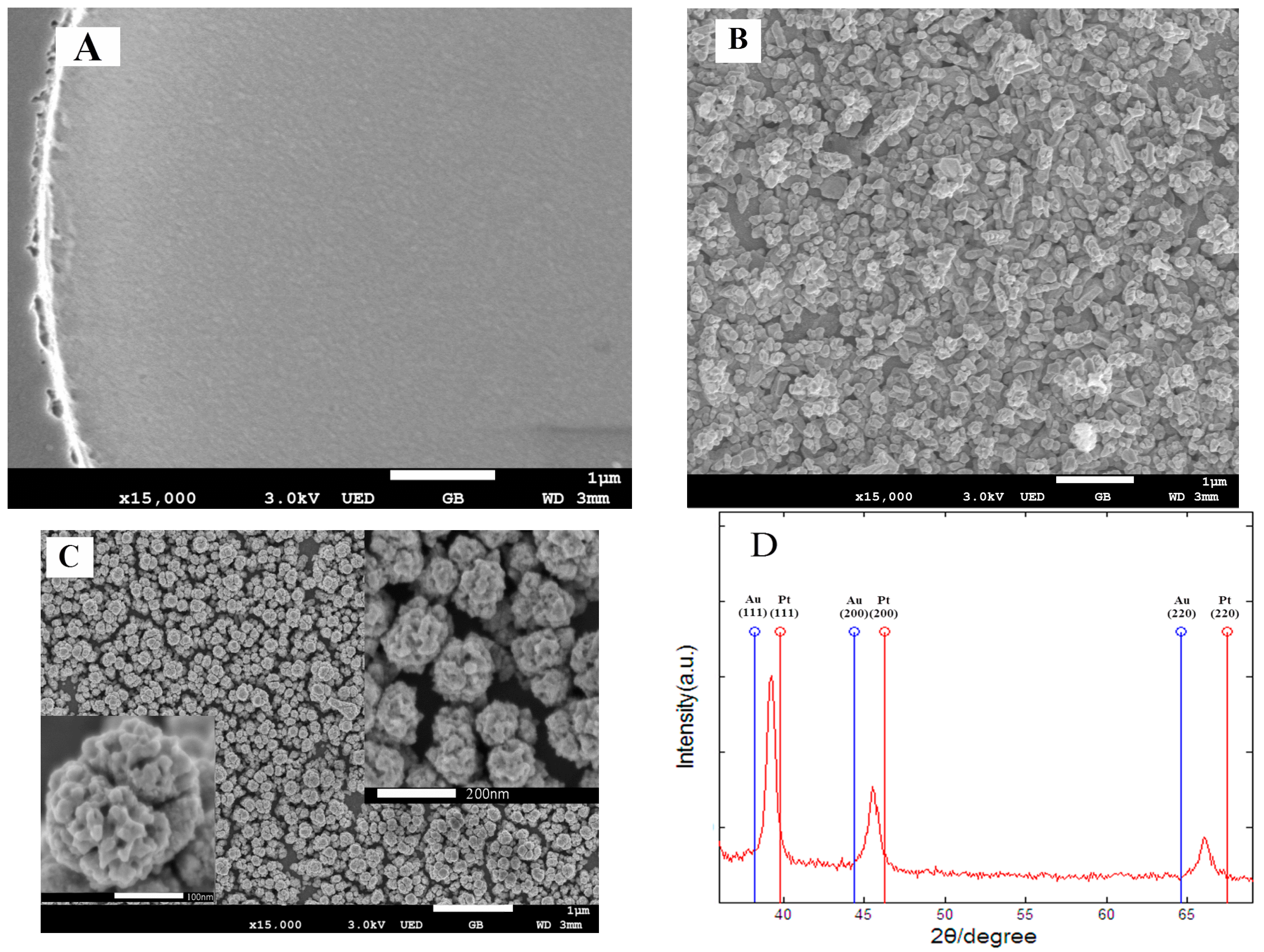
3.1. Morphological and Structural Analysis

The surface morphologies of the modified Au microelectrode sites were examined by scanning electron microscopy (SEM). As shown in Figure 2A, the bare Au microelectrode site possessed a smooth surface. After electrochemical deposition of AuNPs (Figure 2B), many gold nanoparticles with irregular shape were densely distributed on the surface of Au microelectrode site, which could increase the surface roughness and reduce impedance of electrode site. The surface morphology of rough-surfaced AuPt alloy nanoparticles with nanoporosity (Figure 2C) showed that the prepared AuPt alloy nanoparticles with a diameter of about 200 nm exhibited cauliflower-like shapes and were densely and uniformly distributed on the surface of Au microelectrode site. From the higher magnification SEM images (inset images of Figure 2C), the AuPt alloy nanoparticles possessed very rough surfaces and many different sizes of pores, which resulted from selective dealloying of Cu in Au-Pt-Cu alloy nanoparticles. Such nanostructures would greatly reduce microelectrode impedance, increase the surface roughness of microelectrode site, provide faster electron transfer rates and facilitate neural signal recording.
In order to further determine the feature of the obtained rough-surfaced AuPt alloy nanoparticles with nanoporosity, an XRD study was conducted. Figure 2D showed the XRD patterns of the obtained AuPt alloy nanoparticles. It was obvious that there appeared three well-resolved diffraction peaks, which could be assigned to the (111), (200) and (220) planes of AuPt alloy nanoparticles, respectively, demonstrating a face-centered cubic (fcc) structure. As is known, the peaks of pure gold nanoparticles (2θ = 38.2°, 44.4° and 64.6°) and pure platinum nanoparticles (2θ = 39.8°, 46.2° and 67.5°) are assigned to the (111), (200), and (220) planes, respectively. As shown in Figure 2D, the (111) peaks of rough-surfaced AuPt alloy nanoparticles fall well between (111) peaks of pure Au and Pt nanoparticles, suggesting that a single-phase alloy of AuPt rather than two separated phases of Pt and Au has been formed by electrochemical co-reduction of Au-Pt-Cu alloy nanoparticles followed by selective dealloying of Cu.

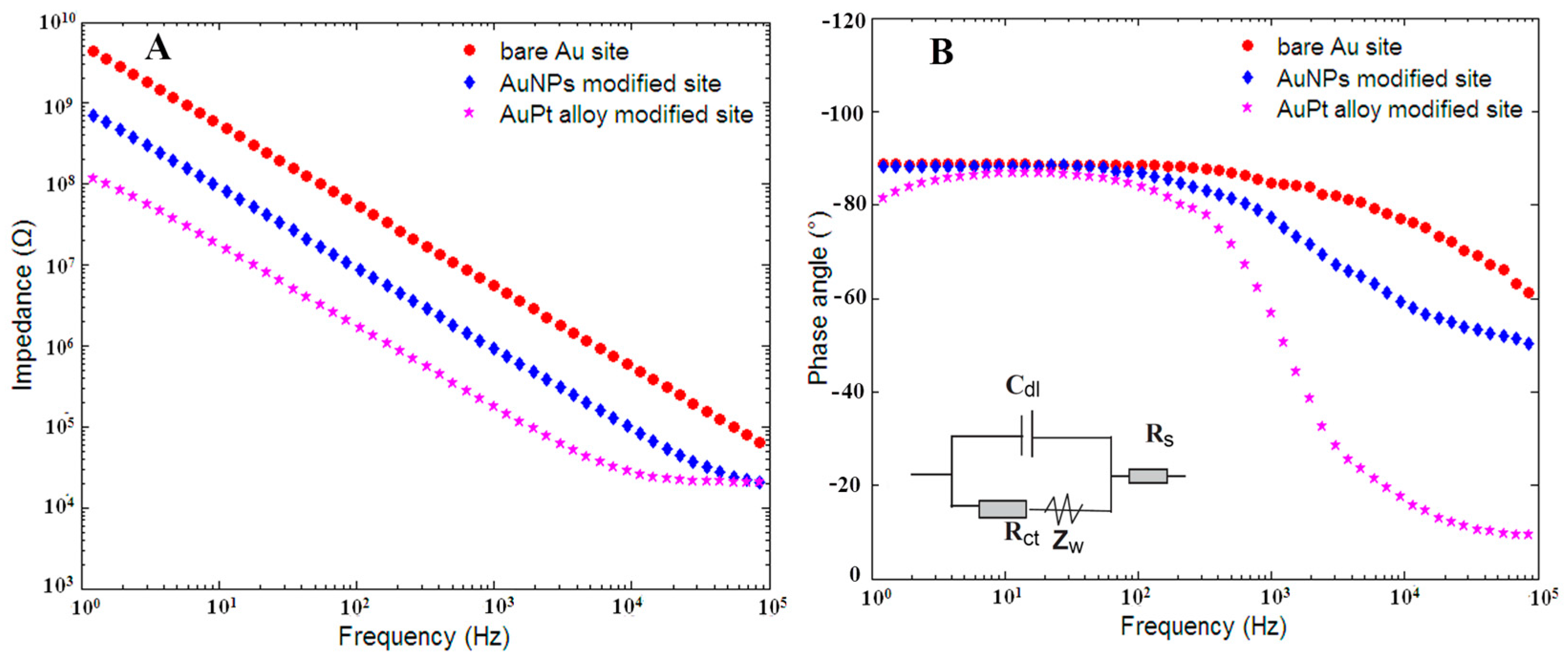
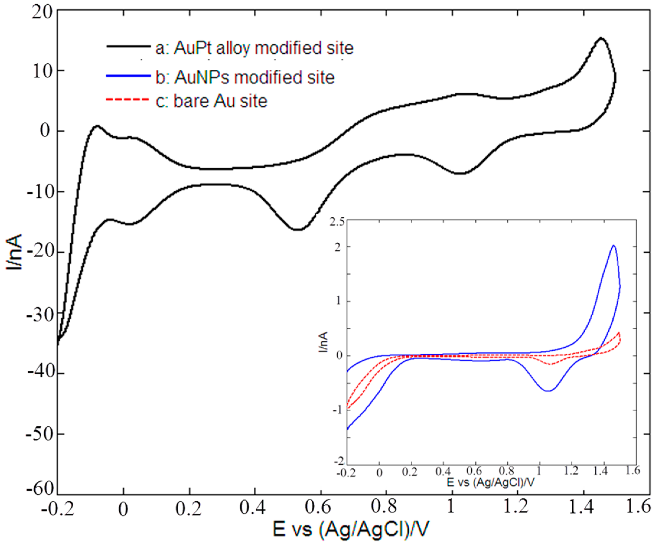
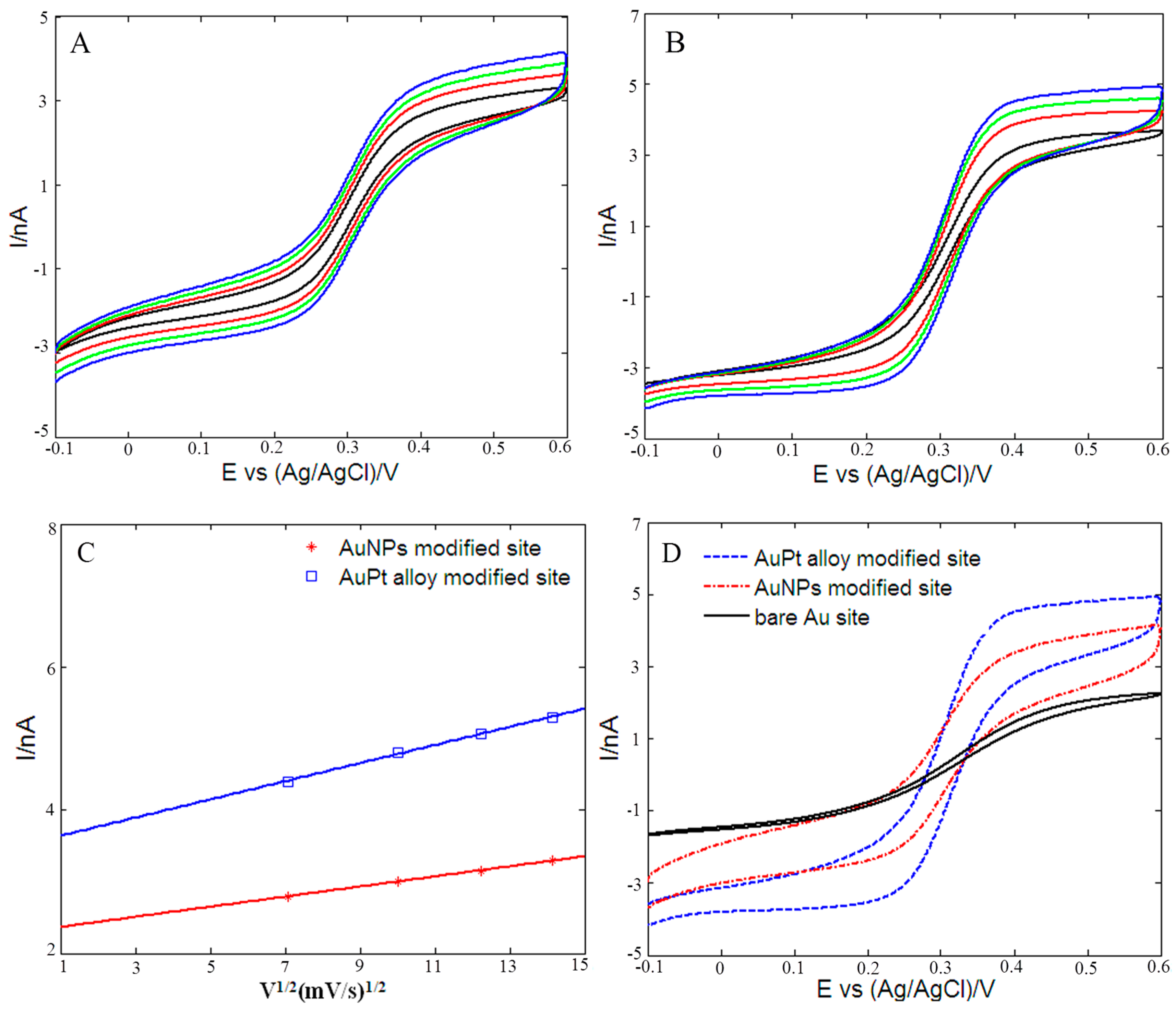
3.2. Electrochemical Behavior

Figure 3 showed the EIS of bare Au microelectrode site, AuNPs and rough-surfaced AuPt alloy nanoparticles modified Au micorelectrode sites. As can be seen in the Figure 3A, the impedances of these three microelectrode sites decreased as the frequency increased from 1 Hz and 100 kHz. The average impedance of bare Au microelectrode site was recorded as 4.9 MΩ, and after electro-deposition of AuNPs, the average impedance decreased to 0.9 MΩ, indicating that AuNPs could greatly increased the surface area and reduced electrode impedance. As for rough-surfaced AuPt alloy nanoparticles with nanoporosity modified microelectrode site, the average impedance further decreased to 0.23 MΩ, which was absolutely due to the very rough surfaces and many nanopores of AuPt alloy nanoparticles. In addition, for AuPt alloy nanoparticles, the synergistic effects of Au and Pt could provide more efficient electron transfer channels, faster electron transfer rates and better electric conductivity. As shown in the Figure 3B, the phase angle of bare Au microelectrode site at 1 kHz was ca. −84.7° and shifted to −77.3°, −56.6° for AuNPs and rough-surfaced AuPt alloy nanoparticles modified microelectrode sites, respectively, which showed that rough-surfaced AuPt alloy nanoparticles modified microelectrode site possessed more resistive electrode-electrolyte interface compared with other two microelectrode sites.
Inset of Figure 3B shows the Randles equivalent circuit of electrode-electrolyte interface and the corresponding three element values could be estimated using the following method. It is well known that this Randles equivalent circuit model includes a solution resistance (Rs) and a double layer capacitor (Cdl) in parallel with the series combination of a charge-transfer resistance (Rct) and Warburg impedance (W). The Warburg impedance W is generally negligible at high frequencies and in solutions with large amount of ions because the time interval is too short to be sufficient for the ion diffusion reacted on the electrode surface [35]. Therefore, the impedance can be simplified and expressed as:
Z ( ω ) = R S + R ct 1 + j ω R ct C dl = Z ( ω ) + jZ ( ω )
where ω is the angular frequency, Z ( ω ) is the real part of impedance and Z ( ω ) is the imaginary part of impedance. Since charge transfer through the electrode-electrolyte interface was shunted by the double-layer capacitance at very high frequency, solution resistance Rs was determined as the asymptotic high frequency impedance:
R s = Z ( f )
and Rct and Cdl at each frequency were determined as [70]:
R ct ( ω ) = Z 2 + ( Z R S ) 2 Z R S
C dl ( ω ) = Z ω [ ( Z R S ) 2 + Z 2 ]
Based on the above-mentioned information, the values of solution resistance Rs, double layer capacitor Cdl and charge-transfer resistance Rct at 1 kHz of these three kinds of microelectrode sites could be estimated using the measured impedance data, and the obtained values were summarized in Table 1. As shown in Table 1, the measured solution resistance Rs of bare Au microelectrode site was about 12.1 KΩ, and it increased to 17.3 KΩ and 20.5 KΩ for AuNPs and rough-surfaced AuPt alloy nanoparticles modified microelectrode site, respectively. For round microelectrode site, the solution resistance Rs could be computed by using following equation [71,72]:
              R s = ρ 4 r
where ρ is the PBS solution resistivity (72 Ω·cm), r is the radius of microelectrode site. It is worth noting that R s   depends on the geometric area and is independent of the effective surface area of the microelectrode site. According to Equation (6), the theoretical value of R s   is 18 KΩ, which is reasonable compared with the measured values (12.1 KΩ, 17.3 KΩ and 20.5 KΩ). In addition, Table 1 shows that the significant reduction of impedance was mainly due to the combination of an increment of double-layer capacitances Cdl and a decrement in charge-transfer resistance Rct.
Figure 4 shows the cyclic voltammetric responses of a bare Au microelectrode site (curve c), AuNPs (curve b) and rough-surfaced AuPt alloy nanoparticles (curve a) modified gold micorelectrode site in 0.5 M H2SO4. As for rough-surfaced AuPt alloy nanoparticles modified gold micorelectrode site (curve a), the potential peaks from −0.1 V to 0.2 V resulted from the hydrogen adsorption/desorption reactions. The reduction peaks at about 0.5 V and 1 V corresponded to the reduction of Au and Pt oxide species, respectively [73], which confirmed the presence of Au and Pt in the rough-surfaced AuPt alloy nanoparticles. As for bare Au microelectrode site (curve c), AuNPs modified site (curve b), the only one potential peak appearing at about 1 V corresponded to the reduction of Au oxide species. However, rough-surfaced AuPt alloy nanoparticles modified gold micorelectrode site showed almost the largest reduction peaks of Au and Pt oxide species in H2SO4 solution, which indicated that the modified microelectrode site possessed the highest metal electrochemical catalytic area.
In order to further investigate the electrochemical properties of these three kinds of microelectrode sites, the cyclic voltammograms at different scan rates (50, 100, 150 and 200 mV/s) were obtained in 0.1 M KCl solution containing 2 mM [Fe(CN)6]3−/4−. Figure 5A,B showed the cyclic voltammograms of AuNPs and rough-surfaced AuPt alloy nanoparticles modified gold micorelectrode sites, respectively. For both AuNPs and rough-surfaced AuPt alloy nanoparticles modified gold micorelectrode sites, the absolute values of reduction and oxidation peak currents were almost equal, and the peak potentials were definite values and independent of the scan rates, which indicated that the electrochemical processes of the modified microelectrode sites in 0.1 M KCl solution containing 2 mM [Fe(CN)6]3−/4− were reversible. In addition, the values of the peak currents increased with scan rates varying from 50 mV/s to 200 mV/s, and reduction and oxidation peak currents of the modified microelectrode sites were proportional to the square root of the scan rates in the range 50–200 mV/s (Figure 5C), suggesting the electrochemical responses were a typical surface-controlled process [74]. The electro-active surface area of microelectrode sites can be estimated for a reversible and diffusion controllable process according to the Randles–Sevcik equation [75,76]:
I p = 2.69 × 10 5 A · D 1 2 · n 3 2 · v 1 2 · C
where I p is the redox peak current, n is the the electron number involved in oxidation reaction, and, here, n is equal to 1 for [Fe(CN)6]3−/4− redox system. C represents the concentration (mol·cm−3) of the ferricyanide (here, C = 2   × 10 3 ), and D is the diffusion coefficient of the molecule in solution (cm2·s−1), which is 6.7 × 10 6 at 25 °C. v is the scan rate (V·s−1) and A represents the electro-active surface area of microelectrode sites.
According to the linear relationship between I pa and v1/2 (Figure 5C), the values of the electro-active surface area were 1579.8 μm2 for AuNPs modified site and 2871.2 μm2 for rough-surfaced AuPt alloy nanoparticles modified micorelectrode site. For bare Au microelectrode site (round-shaped, diameter of 20 μm), the geometric area is 314.2 μm2. Therefore, electro-active surface area of rough-surfaced AuPt alloy nanoparticles modified micorelectrode site is almost 9.1 times as large as that of bare gold microelectrode site, showing that rough-surfaced AuPt alloy nanoparticles modified micorelectrode site possessed a very rough surface. Figure 5D showed the cyclic voltammograms of these three microelectrode sites in the same 2 mM [Fe(CN)6]3−/4− at scan rate of 200 mV/s. It was obvious that bare Au microelectrode site exhibited small redox peak currents, and after deposition of AuNPs, the redox peak currents increased significantly. As for rough-surfaced AuPt alloy nanoparticles modified micorelectrode site, the redox peak currents further increased, indicating that the order of redox peak current was consistent with the above-calculated electro-active surface area, i.e., bare Au microelectrode site < Au NPs modified microelectrode site < AuPt alloy nanoparticles modified microelectrode site. These results implied that the rough-surfaced AuPt alloy nanoparticles modified micorelectrode site possessed bigger electro-active surface areas and higher conductivity compared with other two microelectrode sites.

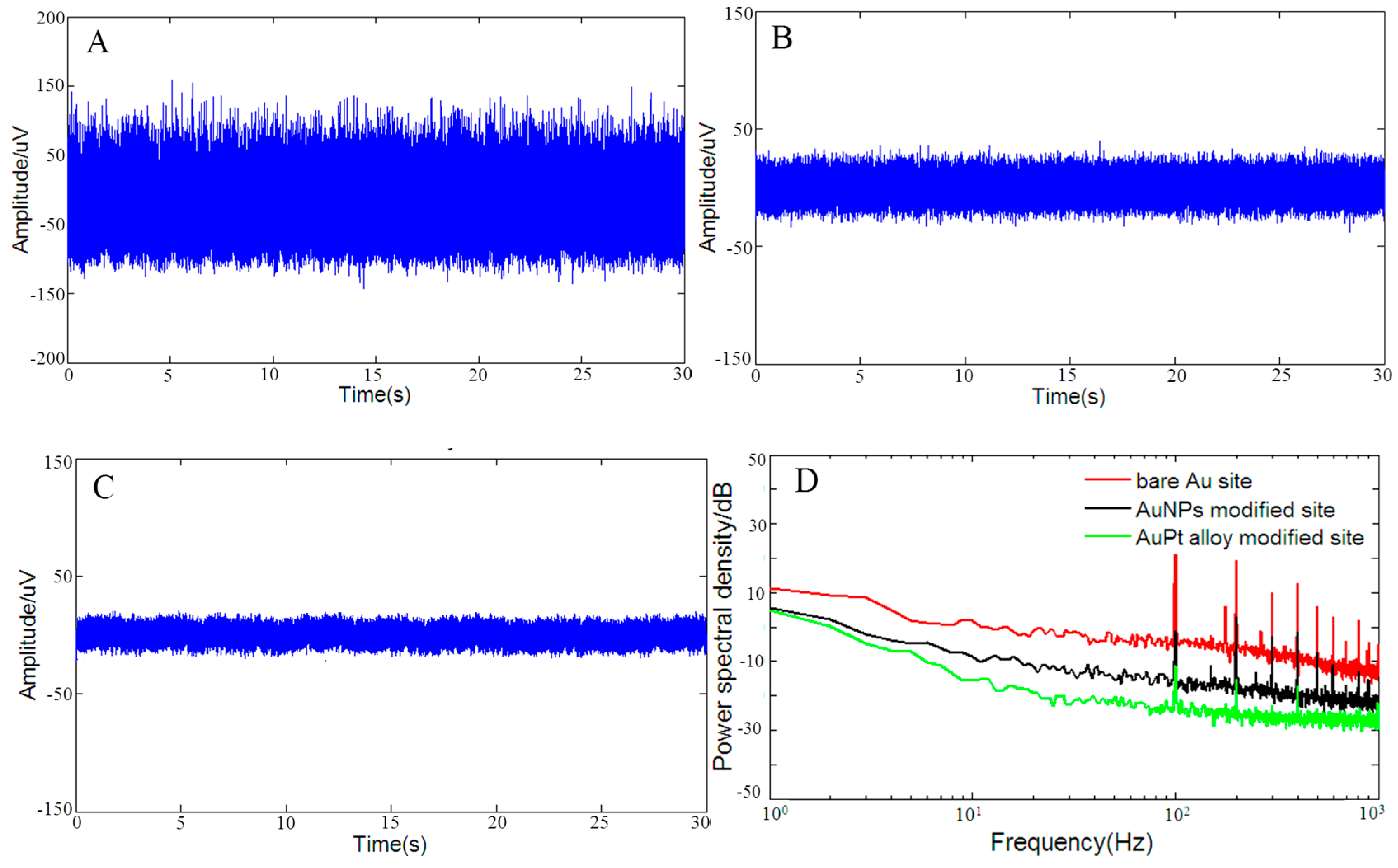
3.3. Background Noise Analysis

In vitro background noises of microelectrode sites included the electronic noise due to the amplifier, the thermal noise and a number of noise sources associated with the double layer interface between solution and microelectrode surface [77]. Thermal noise was generated by the thermal agitation of electrons inside an electrical conductor at equilibrium, and it was considered as one of the main noise sources for microelectrode site recordings [36]. Thermal noise could be computed using the following equation [77]:
V rms = k · T · Z real · f
where V rms is the thermal noise in the form of root mean square,   k is the Boltzmann constant, T is the absolute temperature, Z real is the average of the measured real part of the component of the complex impedance and f is the bandwidth over which the noise is measured. Therefore, noise is proportional to the square root of the impedance of the electrode and decreasing the impedance of the microelectrode sites should lower the thermal noise.
Figure 6 shows the in vitro background noises recorded in 0.1 M PBS of bare Au microelectrode site (Figure 6A), AuNPs (Figure 6B) and rough-surfaced AuPt alloy nanoparticles (Figure 6C) modified micorelectrode sites. Here, noise level was computed in the form of root mean square V rms , which was defined as V rms = y k 2 K , where y k (k = 1 − K, K = 60,000, i.e., two seconds data points) was the noise amplitude at sampling point k. Therefore, the measured V rms in the the frequency band of 1–7500 Hz was 34.1   μ V rms , 11.4 μ V rms and 7.5 μ V rms for bare Au microelectrode site, AuNPs and rough-surfaced AuPt alloy nanoparticles modified micorelectrode sites, respectively, which indicated that noise of rough-surfaced AuPt alloy nanoparticles modified micorelectrode site was lowered to only 21.9% of that of bare Au microelectrode site. As shown in frequency domain (Figure 6D), it was obvious that rough-surfaced AuPt alloy nanoparticles modified micorelectrode site possessed the lowest average noise power in the frequency band of 1–1000 Hz. Based on Equation (8), the calculated noise level from 1 to 7500 Hz was 19.8   μ V rms , 6.1 μ V rms   and 4.7 μ V rms for bare Au microelectrode site, AuNPs and rough-surfaced AuPt alloy nanoparticles modified micorelectrode sites, respectively, which showed that the measured noise were reasonable compared to the calculated noises and thermal noise decreased with the increase of microelectrode surface area.
Márton et al. [78] pointed out that the in vitro and in vivo electrochemical impedance were different, and the reason is that impedance depends not only on electrode, but on solution properties as well [79,80]. As for 0.1 M PBS solution, the resistivity is 72 Ω·cm, but the average resistivity of gray mattey is 4.11 Ω·m (411 Ω·cm) according to a review study [81]. Although the data of in vivo electrochemical impedance are not measured, we can compare in vitro solution resistance Rs and in vivo solution resistance Rs according to Equation (6). The computed in vitro and in vivo Rs of AuPt alloy modified recording microelectrodes is 20.5 KΩ and 117 KΩ, respectively. Even though we did not obtain the data of in vivo electrochemical impedance, it can be inferred that the in vivo impedance of AuPt alloy modified microelectrodes is bigger than our measured in vitro impedance, which will result in a certain increase of in vivo thermal noise. However, as for in vivo extracellular recording, the recorded neural signals are affected by biological and non-biological noise sources [77]. The non-biological noise sources include the electronic noise of amplifier, the thermal noise and some noise sources associated with double layer interface between solution and microelectrode surface. The biological noise sources include: (a) the additional thermal noise component due to the presence of brain tissue, which increases the electrode impedance real part; and (b) small neural signals, emitted by distant neurons/neuronal processes too far to be detected as single units and therefore considered as noise for most neural signal analyses. In summary, the background noise components of recorded in vivo neural signals are complex. Here, we do not want to focus on analysis of in vivo background noise components, alternatively, it is helpful to use e.g., signal-to-noise ratio (SNR) to evaluate in vivo extracellular recording performance of AuPt alloy modified recording microelectrodes. Therefore, in the next section, the in vivo spike signal recordings were carried out.

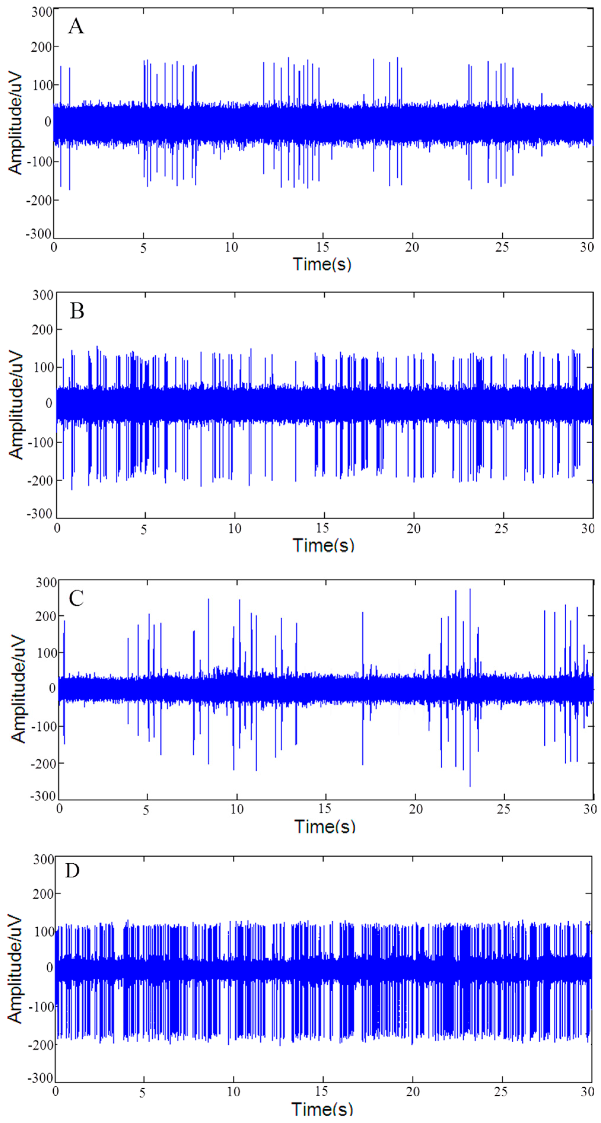
3.4. Improvement of In Vivo Extracellular Recording

On the one hand, it was necessary to confirm that the rough-surfaced AuPt alloy nanoparticles increased the surface area of microelectrode sites without compromising single-unit selectivity. On the other hand, it might be interesting to explore whether rough-surfaced AuPt alloy nanoparticles modified microelectrode sites improved performance of in vivo spike signal recordings. Therefore, in vivo spike signals recording was performed in SD rats. It was obvious that bare Au sites were not suitable for in vivo spike signal recording due to its high impedance (4.9 MΩ), therefore, we only carried out spike signals recordings at AuNPs and rough-surfaced AuPt alloy nanoparticles modified microelectrode sites. Five AuNPs and five rough-surfaced AuPt alloy nanoparticles modified microelectrode sites were used to perform ten times in vivo spike signal recordings, respectively.
Figure 7 shows typical segments of spontaneous spike signals and sorted spikes recorded at AuNPs (Figure 7A,B) and rough-surfaced AuPt alloy nanoparticles (Figure 7C,D) modified microelectrode site, respectively. As shown in Figure 7, two kinds of firing patterns of lateral globus pallidus (GPe) neurons [82], i.e., high frequency firing with pause (Figure 7B,D) and low frequency firing with pause (Figure 7A,C) were detected at both modified Au sites. In addition, the average spike amplitude and average SNR of both modified microelectrode sites were calculated and shown in Table 2. As shown in Table 2, the average spike amplitude of AuPt alloy nanoparticles modified sites was similar with that of AuNPs modified sites, but the average SNR was obviously higher than that of AuNPs modified sites, which was mainly due to the reduction of in vivo recording background noise at AuPt alloy nanoparticles modified sites. The reduction of in vivo recording background noise at AuPt alloy nanoparticles modified sites might be due to reduction of impedance (Figure 3) and resulting decrease of thermal noise (Figure 6). The impedance of electrodes at 1 kHz was thought to affect the SNR of spike recordings because spike waveforms were usually around this frequency. The above results indicated that the rough-surfaced AuPt alloy nanoparticles not only increased the surface area of microelectrode sites without compromising single-unit selectivity, but also improved SNR of in vivo spike signals.
Comparison of microelectrode properties with other modified microelectrodes reported in the literature is summarized and shown in Table 3. As shown in Table 3, SNR at rough-surfaced AuPt alloy nanoparticles modified sites is comparable to those of surfactant-templated ordered PEDOT [45] and PEDOT-PSS composite/Poly(p-xylylene) [34] modified sites, but is bigger than those of PEDOT [38] and PEDOT/pTS composite [42] modified sites. In summary, rough-surfaced AuPt alloy nanoparticles modified microelectrode sites exhibited relatively high average spike SNR. The impedance at 1 kHz is smaller than those of PEDOT [38] and GaP nanowires [83] modified sites, but is bigger than those of other microelectrodes. However, impedance is closely related to the size of microelectrode site. Because the sizes of microelectrode sites reported in the literatures are different, so it is not convenient to compare their impedance values.
As for Reference [61], the authors also used AuPt alloy nanoparticles to modify microelectrode sites, but the preparation method is different from ours. The authors in Reference [61] electrochemically deposited AuPt bimetallic nanoparticles on gold multi-electrode arrays to improve its in vitro neuronal recording performance. However, we modified the Michigan type silicon electrodes via electro-co-deposition of Au-Pt-Cu alloy nanoparticles followed by chemical dealloying Cu, and applied it for in vivo neuronal recordings. It is well known that the surface morphology of nanoparticles plays a key role in their properties, and nanoparticles with different surface morphologies may possess different electrochemical characteristics. As for AuPt nanoparticles modified sites [61], its impedance at 1 kHz is 6.67% of that of bare sites, i.e., the impedance of the bare sites decreased from 6 × 10⁵ Ω (at 1 kHz) to 4.0 × 10⁴ Ω (at 1 kHz) upon electro-deposition of AuPt nanoparticles. However, for our prepared rough-surfaced AuPt alloy nanoparticles modified sites, its impedance at 1 kHz is 0.23 MΩ, which is only 4.7% of that of bare microelectrode sites (4.9 MΩ). Therefore, although absolute impedance value of rough-surfaced AuPt alloy nanoparticles modified sites is bigger than that of AuPt nanoparticles modified sites, we believe that rough-surfaced AuPt alloy nanoparticles possessed faster electron transfer rate than AuPt nanoparticles modified sites.

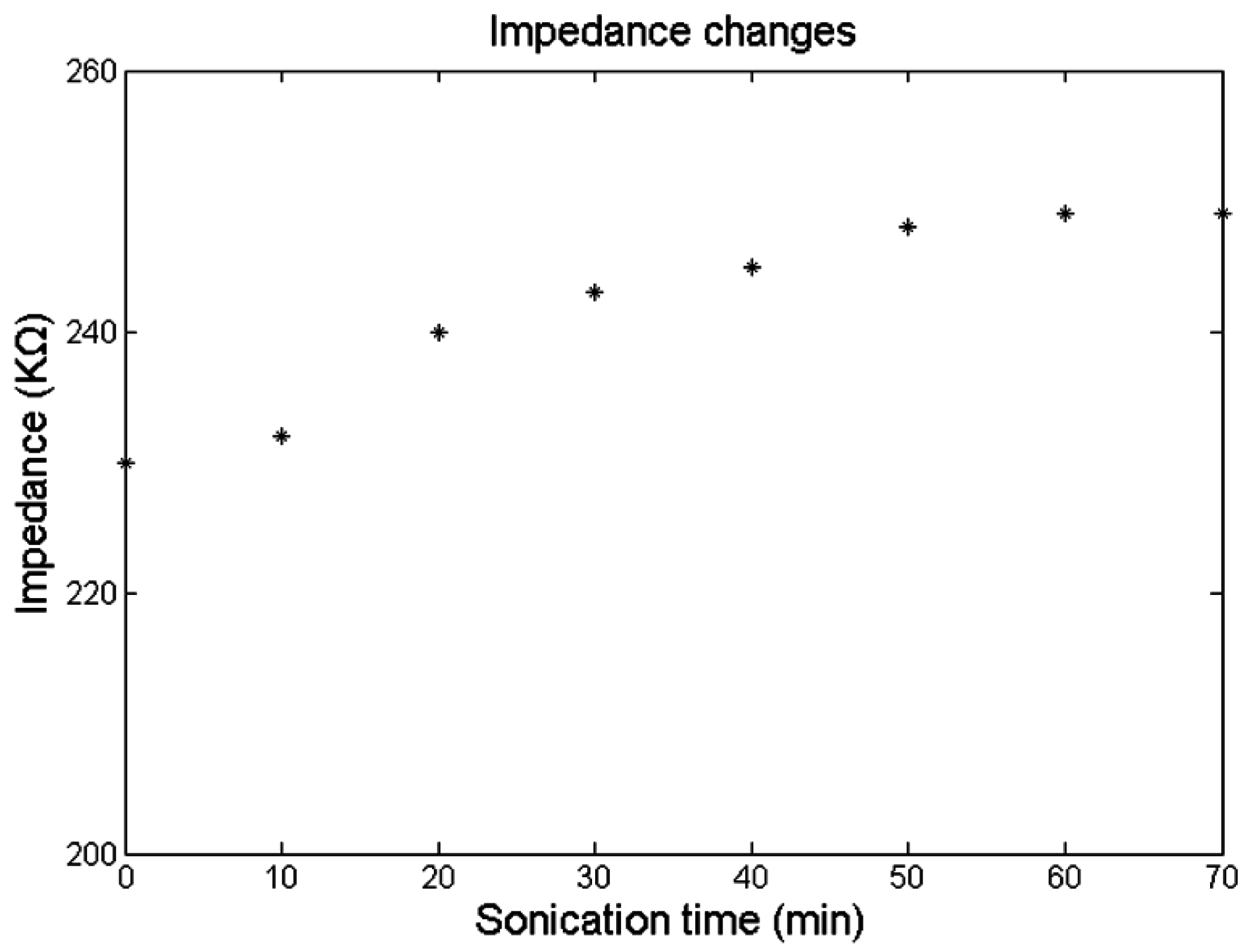
3.5. Durability Test

To confirm the mechanical durability of the prepared rough-surfaced AuPt alloy nanoparticles, the as-prepared rough-surfaced AuPt alloy nanoparticles modified microelectrode arrays were sonicated in PBS seven times (ten min each time) and after each sonication microelectrode impedance was tested. Figure 8 showed the impedance changes (at 1 kHz) during ultrasonic treatment. The initial average impedance (at 1 kHz) of rough-surfaced AuPt alloy nanoparticles modified microelectrode arrays was 230 KΩ (0.23 MΩ) and after seven times of ultrasonic treatment the average impedance (at 1 kHz) increased to 249 KΩ, which showed an increase of only 8.3% of initial impedance. These results confirmed the mechanical durability of rough-surfaced AuPt alloy nanoparticles modified microelectrode arrays.

4. Conclusions

In this paper, rough-surfaced AuPt alloy nanoparticles with nanoporosity were deposited on gold microelectrode sites through electro-co-deposition of Au-Pt-Cu alloy nanoparticles, followed by chemical dealloying Cu. Both in vitro and in vivo methods including SEM, EIS, CV and in vivo neural recording were used to evaluate the performance of the modified microelectrode sites. In conclusion, rough-surfaced AuPt alloy nanoparticles could greatly increase the effective surface area and reduce the impedance of microelectrodes, which leaded to reduction of thermal noise and improvement of in vivo spike recordings. The origin of impedance reduction was studied by using a simple equivalent circuit and the results showed that the significant reduction of impedance was mainly due to the combination of an increment of double-layer capacitance and a decrement in charge-transfer resistance. In short, this paper proposed a convenient way for reducing impedance of microelectrode sites and improving the quality of in vivo spike recordings.

Acknowledgments

This work was financially supported by the National Natural Science Foundation of China (Grant No. 61271088 and 61431012).

Author Contributions

Jue Wang guided the experiments. Ruxue Gong and Liang Zheng performed the in vivo neural recording experiments. Zongya Zhao carried out the majority of the experiments, including the fabrication and electrochemical measurements of the obtained microelectrode array, and wrote the paper.

Conflicts of Interest

The authors declare no conflict of interest.

References

  1. Alegre, M.; Lopez-Azcarate, J.; Tainta, M.; Rodriguez-Oroz, M.C.; Valencia, M.; Gonzalez, R.; Guridi, J.; Iriarte, J.; Obeso, J.A.; Artieda, J. Coupling between beta and high-frequency activity in the human subthalamic nucleus may be a pathophysiological mechanism in parkinson’s disease. J. Neurosci. 2010, 30, 6667–6677. [Google Scholar]
  2. Dupre, K.B.; Cruz, A.V.; Mccoy, A.J.; Delaville, C.; Gerber, C.M.; Eyring, K.W.; Walters, J.R. Effects of l-dopa priming on cortical high beta and high gamma oscillatory activity in a rodent model of parkinson’s disease. Neurobiol. Dis. 2015, 86, 1–15. [Google Scholar] [CrossRef] [PubMed]
  3. Geng, X.; Xie, J.; Wang, X.; Wang, X.; Xiao, Z.; Hou, Y.; Lei, C.; Min, L.; Qu, Q.; He, T. Altered neuronal activity in the pedunculopontine nucleus: An electrophysiological study in a rat model of parkinson’s disease. Behav. Brain Res. 2016, 305, 57–64. [Google Scholar] [CrossRef] [PubMed]
  4. Lalo, E.; Thobois, S.; Sharott, A.; Polo, G.; Mertens, P.; Pogosyan, A.; Brown, P. Patterns of bidirectional communication between cortex and basal ganglia during movement in patients with parkinson disease. J. Neurosci. 2008, 28, 3008–3016. [Google Scholar] [CrossRef] [PubMed]
  5. Wang, M.; Li, M.; Geng, X.; Song, Z.; Albers, H.E.; Yang, M.; Zhang, X.; Xie, J.; Qu, Q.; He, T. Altered neuronal activity in the primary motor cortex and globus pallidus after dopamine depletion in rats. J. Neurol. Sci. 2015, 348, 231–240. [Google Scholar] [CrossRef] [PubMed]
  6. Liu, T.; Bai, W.; Ju, W.; Xin, T. An aberrant link between gamma oscillation and functional connectivity in aβ 1–42 -mediated memory deficits in rats. Behav. Brain Res. 2016, 297, 51–58. [Google Scholar] [CrossRef] [PubMed]
  7. Cheung, K.C. Implantable microscale neural interfaces. Biomed. Microdevices 2007, 9, 923–938. [Google Scholar] [CrossRef] [PubMed]
  8. Herwik, S.; Kisban, S.; Aarts, A.A.A.; Seidl, K.; Girardeau, G.; Benchenane, K.; Zugaro, M.B.; Wiener, S.I.; Paul, O.; Neves, H.P. Fabrication technology for silicon-based microprobe arrays used in acute and sub-chronic neural recording. J. Micromech. Microeng. 2009, 19, 74008–74011. [Google Scholar] [CrossRef]
  9. Norlin, P.; Kindlundh, M.; Mouroux, A.; Yoshida, K.; Hofmann, U.G. A 32-site neural recording probe fabricated by DRIE of SOI substrates. J. Micromech. Microeng. 2002, 12, 414–419. [Google Scholar] [CrossRef]
  10. Wise, K.D.; Angell, J.B.; Starr, A. An integrated-circuit approach to extracellular microelectrodes. IEEE Trans. Biomed. Eng. 1970, 17, 238–247. [Google Scholar] [CrossRef] [PubMed]
  11. Wise, K.D.; Sodagar, A.M.; Yao, Y.; Gulari, M.N.; Perlin, G.E.; Najafi, K. Microelectrodes, microelectronics, and implantable neural microsystems. Proc. IEEE 2008, 96, 1184–1202. [Google Scholar] [CrossRef]
  12. Fekete, Z. Recent advances in silicon-based neural microelectrodes and microsystems: A review. Sens. Actuaturs B Chem. 2015, 215, 300–315. [Google Scholar] [CrossRef]
  13. Aarts, A.; Pereira Neves, H.; Puers, R.; Van Hoof, C. An interconnect for out-of-plane assembled biomedical probe arrays. J. Micromech. Microeng. 2008, 18, 777–786. [Google Scholar] [CrossRef]
  14. Chang, C.W.; Chiou, J.C. Development of a three dimensional neural sensing device by a stacking method. Sensors 2009, 10, 4238–4252. [Google Scholar] [CrossRef] [PubMed]
  15. Wang, M.F.; Maleki, T.; Ziaie, B. A self-assembled 3d microelectrode array. J. Micromech. Microeng. 2010, 20, 035013. [Google Scholar] [CrossRef]
  16. Du, J.; Roukes, M.L.; Masmanidis, S.C. Dual-side and three-dimensional microelectrode arrays fabricated from ultra-thin silicon substrates. J. Micromech. Microeng. 2009, 19, 1403–1407. [Google Scholar] [CrossRef]
  17. Lopez, C.M.; Andrei, A.; Mitra, S.; Welkenhuysen, M.; Eberle, W.; Bartic, C.; Puers, R.; Yazicioglu, R.F.; Gielen, G.G.E. An implantable 455-active-electrode 52-channel cmos neural probe. IEEE J. Solid State Circuits 2013, 49, 248–261. [Google Scholar] [CrossRef]
  18. Torfs, T.; Aarts, A.; Erismis, M.A.; Aslam, J. Two-dimensional multi-channel neural probes with electronic depth control. IEEE Trans. Biomed. Circuits Syst. 2011, 5, 403–412. [Google Scholar] [CrossRef] [PubMed]
  19. Song, Y.K.; Patterson, W.R.; Bull, C.W.; Beals, J. Development of a chipscale integrated microelectrode/microelectronic device for brain implantable neuroengineering applications. IEEE Trans. Neural Syst. Rehab. Eng. 2005, 13, 220–226. [Google Scholar] [CrossRef] [PubMed]
  20. Seidl, K.; Spieth, S.; Herwik, S.; Steigert, J.; Zengerle, R.; Paul, O.; Ruther, P. In-plane silicon probes for simultaneous neural recording and drug delivery. J. Micromech. Microeng. 2010, 20, 105006–105011. [Google Scholar] [CrossRef]
  21. Spieth, S.; Schumacher, A.; Holtzman, T.; Rich, P.D.; Theobald, D.E.; Dalley, J.W.; Nouna, R.; Messner, S.; Zengerle, R. An intra-cerebral drug delivery system for freely moving animals. Biomed. Microdev. 2012, 14, 799–809. [Google Scholar] [CrossRef] [PubMed]
  22. Pongrácz, A.; Fekete, Z.; Márton, G.; Bérces, Z.; Ulbert, I.; Fürjes, P. Deep-brain silicon multielectrodes for simultaneous in vivo neural recording and drug delivery. Sens. Actuators B Chem. 2013, 189, 97–105. [Google Scholar] [CrossRef]
  23. Wu, F.; Stark, E.; Im, M.; Cho, I.J.; Yoon, E.S.; Buzsáki, G.; Wise, K.D.; Yoon, E. An implantable neural probe with monolithically integrated dielectric waveguide and recording electrodes for optogenetics applications. J. Neural Eng. 2013, 10, 056012. [Google Scholar] [CrossRef] [PubMed]
  24. Royer, S.; Zemelman, B.V.; Barbic, M.; Losonczy, A.; Buzsáki, G.; Magee, J.C. Multi-array silicon probes with integrated optical fibers: Light-assisted perturbation and recording of local neural circuits in the behaving animal. Eur. J. Neurosci. 2010, 31, 2279–2291. [Google Scholar] [CrossRef] [PubMed]
  25. Kiss, M.; Földesy, P.; Fekete, Z. Optrode for multimodal deep-brain infrared stimulation. Procedia Eng. 2014, 87, 1537–1540. [Google Scholar] [CrossRef]
  26. Abaya, T.V.F.; Diwekar, M.; Blair, S.; Tathireddy, P.; Rieth, L.; Clark, G.A.; Solzbacher, F. Characterization of a 3D optrode array for infrared neural stimulation. Biomed. Opt. Exp. 2012, 3, 2200–2219. [Google Scholar] [CrossRef] [PubMed]
  27. Zorzos, A.N.; Boyden, E.S.; Fonstad, C.G. Multiwaveguide implantable probe for light delivery to sets of distributed brain targets. Opt. Lett. 2010, 35, 4133–4135. [Google Scholar] [CrossRef] [PubMed]
  28. Kanno, S.; Lee, S.; Harashima, T.; Kuki, T.; Kino, H.; Mushiake, H.; Yao, H.; Tanaka, T. Multiple optical stimulation to neuron using si opto-neural probe with multiple optical waveguides and metal-cover for optogenetics. In Proceedings of the 35th Annual International Conference of the IEEE EMBS, Osaka, Japan, 3–7 July, 2013; pp. 253–256.
  29. Johnson, M.D.; Franklin, R.K.; Gibson, M.D.; Brown, R.B.; Kipke, D.R. Implantable microelectrode arrays for simultaneous electrophysiological and neurochemical recordings. J. Neurosci. Methods 2008, 174, 62–70. [Google Scholar] [CrossRef] [PubMed]
  30. Frey, O.; Pd, V.D.W.; Spieth, S.; Brett, O.; Seidl, K.; Paul, O.; Ruther, P.; Zengerle, R.; de Rooij, N.F. Biosensor microprobes with integrated microfluidic channels for bi-directional neurochemical interaction. J. Neural Eng. 2011, 8, 066001. [Google Scholar] [CrossRef] [PubMed]
  31. Frey, O.; Holtzman, T.; Mcnamara, R.M.; Theobald, D.E.H.; Wal, P.D.V.D.; Rooij, N.F.D.; Dalley, J.W.; Koudelka-Hep, M. Simultaneous neurochemical stimulation and recording using an assembly of biosensor silicon microprobes and su-8 microinjectors. Sens. Actuaturs B Chem. 2011, 154, 96–105. [Google Scholar] [CrossRef]
  32. Du, J.; Blanche, T.J.; Harrison, R.R.; Lester, H.A.; Masmanidis, S.C. Multiplexed, high density electrophysiology with nanofabricated neural probes. PLoS ONE 2011, 6, e26204. [Google Scholar] [CrossRef] [PubMed]
  33. James, C.D.; Spence, A.J.H.; Dowell-Mesfin, N.M.; Hussain, R.J. Extracellular recordings from patterned neuronal networks using planar microelectrode arrays. IEEE Trans. Biomed. Eng. 2004, 51, 1640–1648. [Google Scholar] [CrossRef] [PubMed]
  34. Paik, S.J.; Park, Y.; Dan’Cho, D. Roughened polysilicon for low impedance microelectrodes in neural probes. J. Micromech. Microeng. 2003, 13, 373–379. [Google Scholar] [CrossRef]
  35. Zhang, S.; Tsang, W.M.; Srinivas, M.; Sun, T. Development of silicon electrode enhanced by carbon nanotube and gold nanoparticle composites on silicon neural probe fabricated with complementary metal-oxide-semiconductor process. Appl. Phys. Lett. 2014, 104, 193105. [Google Scholar] [CrossRef]
  36. Desai, S.A.; Rolston, J.D.; Guo, L.; Potter, S.M. Improving impedance of implantable microwire multi-electrode arrays by ultrasonic electroplating of durable platinum black. Front. Neuroeng. 2010, 3, 5. [Google Scholar] [CrossRef] [PubMed]
  37. Keefer, E.W.; Botterman, B.R.; Romero, M.I.; Rossi, A.F.; Gross, G.W. Carbon nanotube coating improves neuronal recordings. Nat. Nanotechnol. 2008, 3, 434–439. [Google Scholar] [CrossRef] [PubMed]
  38. Castagnola, E.; Ansaldo, A.; Fadiga, L.; Ricci, D. Chemical vapour deposited carbon nanotube coated microelectrodes for intracortical neural recording. Phys. Status Solidi B 2010, 247, 2703–2707. [Google Scholar] [CrossRef]
  39. Cogan, S.F.; Ehrlich, J.; Plante, T.D.; Smirnov, A.; Shire, D.B.; Gingerich, M.; Rizzo, J.F. Sputtered iridium oxide films for neural stimulation electrodes. J. Biomed. Mater. Res. B Appl. Biomater. 2008, 89, 353–361. [Google Scholar] [CrossRef] [PubMed]
  40. Negi, S.; Bhandari, R.; Rieth, L.; Solzbacher, F. In vitro comparison of sputtered iridium oxide and platinum-coated neural implantable microelectrode arrays. Biomed. Mater. 2010, 5, 015007. [Google Scholar] [CrossRef] [PubMed]
  41. Ludwig, K.A.; Langhals, N.B.; Joseph, M.D.; Richardson-Burns, S.M.; Hendricks, J.L.; Kipke, D.R. Poly(3,4-ethylenedioxythiophene) (pedot) polymer coatings facilitate smaller neural recording electrodes. J. Neural Eng. 2011, 8, 200–208. [Google Scholar] [CrossRef] [PubMed]
  42. Harris, A.R.; Morgan, S.J.; Chen, J.; Kapsa, R.M.; Wallace, G.G.; Paolini, A.G. Conducting polymer coated neural recording electrodes. J. Neural. Eng. 2013, 10, 79–88. [Google Scholar] [CrossRef] [PubMed]
  43. Mandal, H.S.; Knaack, G.L.; Charkhkar, H.; Mchail, D.G.; Kastee, J.S.; Dumas, T.C.; Peixoto, N.; Rubinson, J.F.; Pancrazio, J.J. Improving the performance of poly(3,4-ethylenedioxythiophene) for brain–machine interface applications. Acta Biomater. 2014, 10, 2446–2454. [Google Scholar] [CrossRef] [PubMed]
  44. Abidian, M.R.; Corey, J.M.; Kipke, D.R.; Martin, D.C. Conducting-polymer nanotubes improve electrical properties, mechanical adhesion, neural attachment, and neurite outgrowth of neural electrodes. Small 2010, 6, 421–429. [Google Scholar] [CrossRef] [PubMed]
  45. Ludwig, K.A.; Uram, J.D.; Yang, J.; Martin, D.C.; Kipke, D.R. Chronic neural recordings using silicon microelectrode arrays electrochemically deposited with a poly(3,4-ethylenedioxythiophene) (pedot) film. J. Neural Eng. 2006, 3, 59–70. [Google Scholar] [CrossRef] [PubMed]
  46. Kozai, T.D.Y.; Langhals, N.B.; Patel, P.R.; Deng, X.; Zhang, H.; Smith, K.L.; Lahann, J.; Kotov, N.A.; Kipke, D.R. Ultrasmall implantable composite microelectrodes with bioactive surfaces for chronic neural interfaces. Nat. Mater. 2012, 11, 1065–1073. [Google Scholar] [CrossRef] [PubMed]
  47. Zhang, H.; Shih, J.; Zhu, J.; Kotov, N.A. Layered nanocomposites from gold nanoparticles for neural prosthetic devices. Nano Lett. 2012, 12, 3391–3398. [Google Scholar] [CrossRef] [PubMed]
  48. Kim, Y.H.; Kim, G.H.; Baek, N.S.; Han, Y.H.; Kim, A.Y.; Chung, M.A.; Jung, S.D. Fabrication of multi-electrode array platforms for neuronal interfacing with bi-layer lift-off resist sputter deposition. J. Micromech. Microeng. 2013, 23, 449–462. [Google Scholar] [CrossRef]
  49. Deng, M.; Yang, X.; Silke, M.; Qiu, W.; Xu, M.; Borghs, G.; Chen, H. Electrochemical deposition of polypyrrole/graphene oxide composite on microelectrodes towards tuning the electrochemical properties of neural probes. Sens. Actuaturs B Chem. 2011, 158, 176–184. [Google Scholar] [CrossRef]
  50. Zhou, H.; Xuan, C.; Li, R.; Tao, L.; Duan, Y.Y. Poly(3,4-ethylenedioxythiophene)/multiwall carbon nanotube composite coatings for improving the stability of microelectrodes in neural prostheses applications. Acta Biomater. 2013, 9, 6439–6449. [Google Scholar] [CrossRef] [PubMed]
  51. Depan, D.; Misra, R.D.K. The development, characterization, and cellular response of a novel electroactive nanostructured composite for electrical stimulation of neural cells. Biomater. Sci. 2014, 2, 1727–1739. [Google Scholar] [CrossRef]
  52. Samba, R.; Herrmann, T.; Zeck, G. Pedot-cnt coated electrodes stimulate retinal neurons at low voltage amplitudes and low charge densities. J. Neural Eng. 2015, 12, 016014. [Google Scholar] [CrossRef] [PubMed]
  53. Gerwig, R.; Fuchsberger, K.; Schroeppel, B.; Link, G.S.; Heusel, G.; Kraushaar, U.; Schuhmann, W.; Stett, A.; Stelzle, M. Pedot-cnt composite microelectrodes for recording and electrostimulation applications: Fabrication, morphology, and electrical properties. Front. Neuroeng. 2011, 5, 8. [Google Scholar] [CrossRef] [PubMed]
  54. Zhao, Z.; Zhang, M.; Chen, X.; Li, Y.; Wang, J. Electrochemical co-reduction synthesis of aupt bimetallic nanoparticles-graphene nanocomposites for selective detection of dopamine in the presence of ascorbic acid and uric acid. Sensors 2015, 15, 16614–16631. [Google Scholar] [CrossRef] [PubMed]
  55. Mohammad, E.; Salehi, K.F.; Norita, M. Electrooxidation of hydroquinone on simply prepared au-pt bimetallic nanoparticles. Sci. China Chem. 2013, 56, 746–754. [Google Scholar]
  56. Leng, J.; Wang, W.M.; Lu, L.M.; Bai, L.; Qiu, X.L. DNA-templated synthesis of ptau bimetallic nanoparticle/graphene nanocomposites and their application in glucose biosensor. Nanoscale Res. Lett. 2014, 9, 1–8. [Google Scholar] [CrossRef] [PubMed]
  57. Lv, J.J.; Wang, A.J.; Ma, X.; Xiang, R.Y.; Chen, J.R.; Feng, J.J. One-pot synthesis of porous pt-au nanodendrites supported on reduced graphene oxide nanosheets toward catalytic reduction of 4-nitrophenol. J. Mater. Chem. A 2014, 3, 290–296. [Google Scholar] [CrossRef]
  58. Choi, J.H.; Jeong, K.J.; Dong, Y.; Han, J.; Lim, T.H.; Lee, J.S.; Sung, Y.E. Electro-oxidation of methanol and formic acid on ptru and ptau for direct liquid fuel cells. J. Power Sources 2006, 163, 71–75. [Google Scholar] [CrossRef]
  59. Balkis, A.; O’Mullane, A.P. Direct electrochemical formation of alloyed aupt nanostructured electrocatalysts for the oxidation of formic acid. Mater. Chem. Phys. 2014, 143, 747–753. [Google Scholar] [CrossRef] [Green Version]
  60. Liu, A.; Tao, X.; Jian, T.; Wu, H.; Zhao, T.; Tang, W. Sandwich-structured ag/graphene/au hybrid for surface-enhanced Raman scattering. Electrochim. Acta 2014, 119, 43–48. [Google Scholar] [CrossRef]
  61. Yong, H.K.; Kim, A.Y.; Kim, G.H.; Han, Y.H.; Chung, M.A.; Jung, S.D. Electrochemical and in vitro neuronal recording characteristics of multi-electrode arrays surface-modified with electro-co-deposited gold-platinum nanoparticles. Biomed. Microdevices 2016, 18, 1–7. [Google Scholar]
  62. Yu, J.; Fujita, T.; Inoue, A.; Sakurai, T.; Chen, M. Electrochemical synthesis of palladium nanostructures with controllable morphology. Nanotechnology 2010, 21, 85601–85607. [Google Scholar] [CrossRef] [PubMed]
  63. Yang, J.; Deng, S.; Lei, J.; Ju, H.; Gunasekaran, S. Electrochemical synthesis of reduced graphene sheet–aupd alloy nanoparticle composites for enzymatic biosensing. Biosens. Bioelectron. 2011, 29, 159–166. [Google Scholar] [CrossRef] [PubMed]
  64. Xu, C.; Wang, R.; Chen, M.; Zhang, Y.; Ding, Y. Dealloying to nanoporous au/pt alloys and their structure sensitive electrocatalytic properties. Phys. Chem. Chem. Phys. 2010, 12, 239–246. [Google Scholar] [CrossRef] [PubMed]
  65. Lee, D.; Jang, H.Y.; Hong, S.; Park, S. Synthesis of hollow and nanoporous gold/platinum alloy nanoparticles and their electrocatalytic activity for formic acid oxidation. J. Colloid. Interface Sci. 2012, 388, 74–79. [Google Scholar] [CrossRef] [PubMed]
  66. Kim, Y.H.; Kim, G.H.; Kim, A.Y.; Han, Y.H.; Chung, M.A.; Jung, S.D. In vitro extracellular recording and stimulation performance of nanoporous gold-modified multi-electrode arrays. J. Neural Eng. 2015, 12, 066029. [Google Scholar] [CrossRef] [PubMed]
  67. Zhao, Z.; Gong, R.; Huang, H.; Wang, J. Design, fabrication, simulation and characterization of a novel dual-sided microelectrode array for deep brain recording and stimulation. Sensors 2016, 16, 880. [Google Scholar] [CrossRef] [PubMed]
  68. Quiroga, R.; Nadasdy, Z.; Ben-Shaul, Y. Unsupervised spike detection and sorting with wavelets and superparamagnetic clustering. Neural Comput. 2004, 16, 1661–1687. [Google Scholar] [CrossRef] [PubMed]
  69. Rutishauser, U.; Schuman, E.M.; Mamelak, A.N. Online detection and sorting of extracellularly recorded action potentials in human medial temporal lobe recordings, in vivo. J. Neurosci. Methods 2006, 154, 204–224. [Google Scholar] [CrossRef] [PubMed]
  70. Wei, X.F.; Grill, W.M. Impedance characteristics of deep brain stimulation electrodes in vitro and in vivo. J. Neural Eng. 2009, 6, 1771–1779. [Google Scholar] [CrossRef] [PubMed]
  71. Chung, T.; Wang, J.Q.; Wang, J.; Cao, B.; Li, Y.; Pang, S.W. Electrode modifications to lower electrode impedance and improve neural signal recording sensitivity. J. Neural Eng. 2015, 12, 056018. [Google Scholar] [CrossRef] [PubMed]
  72. Franks, W.; Schenker, I.; Schmutz, P.; Hierlemann, A. Impedance characterization and modeling of electrodes for biomedical applications. IEEE Trans. Biomed. Eng. 2005, 52, 1295–1302. [Google Scholar] [CrossRef] [PubMed]
  73. Shahrokhian, S.; Rastgar, S. Construction of an electrochemical sensor based on the electrodeposition of au-pt nanoparticles mixtures on multi-walled carbon nanotubes film for voltammetric determination of cefotaxime. Analyst 2012, 137, 2706–2715. [Google Scholar] [CrossRef] [PubMed]
  74. Fang, B.; Wang, G.; Zhang, W.; Li, M.; Kan, X. Fabrication of Fe3O4 nanoparticles modified electrode and its application for voltammetric sensing of dopamine. Electroanalysis 2005, 17, 744–748. [Google Scholar] [CrossRef]
  75. Li, Y.; Yuan, R.; Chai, Y.; Song, Z. Electrodeposition of gold–platinum alloy nanoparticles on carbon nanotubes as electrochemical sensing interface for sensitive detection of tumor marker. Electrochim. Acta 2011, 56, 6715–6721. [Google Scholar] [CrossRef]
  76. Reddy, S.; Swamy, B.E.K.; Jayadevappa, H. Cuo nanoparticle sensor for the electrochemical determination of dopamine. Electrochim. Acta 2012, 61, 78–86. [Google Scholar] [CrossRef]
  77. Baranauskas, G.; Maggiolini, E.; Castagnola, E.; Ansaldo, A.; Mazzoni, A.; Angotzi, G.N.; Vato, A.; Ricci, D.; Panzeri, S.; Fadiga, L. Carbon nanotube composite coating of neural microelectrodes preferentially improves the multiunit signal-to-noise ratio. J. Neural Eng. 2011, 8, 066013. [Google Scholar] [CrossRef] [PubMed]
  78. Márton, G.; Bakos, I.; Fekete, Z.; Ulbert, I.; Pongrácz, A. Durability of high surface area platinum deposits on microelectrode arrays for acute neural recordings. J. Mater. Sci. Mater. Med. 2013, 25, 931–940. [Google Scholar] [CrossRef] [PubMed]
  79. Nicholson, C.; Phillips, J.M. Ion diffusion modified by tortuosity and volume fraction in the extracellular microenvironment of the rat cerebellum. J. Physiol. 1981, 321, 225–257. [Google Scholar] [CrossRef] [PubMed]
  80. Abidian, M.R.; Martin, D.C. Experimental and theoretical characterization of implantable neural microelectrodes modified with conducting polymer nanotubes. Biomaterials 2008, 29, 1273–1283. [Google Scholar] [CrossRef] [PubMed]
  81. Latikka, J.A.; Hyttinen, J.A.; Kuurne, T.A.; Eskola, H.J. The conductivity of brain tissues: Comparison of results in vivo and in vitro measurements. In Proceedings of the 23rd Annual International Conference of the IEEE Engineering in Medicine and Biology Society, Istanbul, Turkey, 25–28 October 2001; pp. 910–912.
  82. Bugaysen, J.; Bronfeld, M.; Tischler, H.; Bargad, I.; Korngreen, A. Electrophysiological characteristics of globus pallidus neurons. PLoS ONE 2010, 5, e12001. [Google Scholar] [CrossRef] [PubMed]
  83. Suyatin, D.B.; Wallman, L.; Thelin, J.; Prinz, C.N.; Jörntell, H.; Samuelson, L.; Montelius, L.; Schouenborg, J. Nanowire-based electrode for acute in vivo neural recordings in the brain. PLoS ONE 2013, 8, e56673. [Google Scholar] [CrossRef] [PubMed]
  84. Angelov, S.D.; Koenen, S.; Jakobi, J.; Heissler, H.E.; Alam, M.; Schwabe, K.; Barcikowski, S.; Krauss, J.K. Electrophoretic deposition of ligand-free platinum nanoparticles on neural electrodes affects their impedance in vitro and in vivo with no negative effect on reactive gliosis. J. Nanobiotechnol. 2016, 14, 1–11. [Google Scholar] [CrossRef] [PubMed]
Figure 1. Schematic diagram of the designed microelectrode array.
Sensors 16 01851 g001
Figure 2. (A) Scanning electron microscopy (SEM) image of bare Au electrode site surface; (B) SEM image of Au nanoparticles (AuNPs); (C) SEM image of rough-surfaced AuPt alloy nanoparticles with nanoporosity; and (D) X-ray diffraction (XRD) patterns of the resulting rough-surfaced AuPt alloy nanoparticles.
Sensors 16 01851 g002
Figure 3. Results from electrochemical impedance spectroscopy (EIS) for: (A) the plot of interfacial impedances; and (B) the plot of phase angle for bare Au microelectrode site, AuNPs and rough-surfaced AuPt alloy nanoparticles modified gold micorelectrode sites. Inset of (B) shows Randles equivalent circuit.
Sensors 16 01851 g003
Figure 4. Cyclic voltammograms of: (a) bare Au microelectrode site; (b) AuNPs; and (c) rough-surfaced AuPt alloy nanoparticles modified gold micorelectrode sites in 0.5 M H2SO4 at scan rate of 50 mV/s.
Sensors 16 01851 g004
Figure 5. Cyclic voltammograms of: AuNPs (A); and rough-surfaced AuPt alloy nanoparticles (B) modified micorelectrode sites in 0.1 M KCl solution containing 2 mM [Fe(CN)6]3−/4−. Scan rate: 50, 100, 150 and 200 mV/s. (C) Plots of linear relationship between anodic peak currents ( I pa ) and square root of the scan rates. (D) Cyclic voltammograms of bare Au microelectrode site, AuNPs and rough-surfaced AuPt alloy nanoparticles modified micorelectrode sites in 2 mM [Fe(CN)6]3−/4− at scan rate of 200 mV/s.
Sensors 16 01851 g005
Figure 6. In vitro background noise varying from 1 to 7500 Hz of: bare Au microelectrode site (A); AuNPs (B); and rough-surfaced AuPt alloy nanoparticles (C) modified micorelectrode sites. (D) Noise power spectral density (PSD) from 1 to 1000 Hz. The 50 Hz power-line interference was filtered from the noise signals.
Sensors 16 01851 g006
Figure 7. In vivo spontaneous spike signals and sorted spikes of AuNPs (A,B); and rough-surfaced AuPt alloy nanoparticles (C,D) modified micorelectrode sites.
Sensors 16 01851 g007
Figure 8. Impedance changes (at 1 kHz) of rough-surfaced AuPt alloy nanoparticles modified microelectrode arrays during ultrasonic treatment.
Sensors 16 01851 g008
Table 1. Element values of Randles equivalent circuit at 1 KHz for three kinds of microelectrode sites.
Microelectrode SiteRs (KΩ)Rct (MΩ)Cdl (μF)
bare Au microelectrode site12.1610.12
AuNPs modified site17.34.60.78
AuPt alloy modified site20.50.454.02
Table 2. Comparison of microelectrode properties between AuNPs and rough-surfaced AuPt alloy nanoparticles modified sites.
AuNPs Modified SiteAuPt Alloy Modified Site
Average impedance at 1 kHz (MΩ)0.90.23
Average spike amplitude ( μ V ) 281.2273.7
Average SNR3.44.8
Note: AuNPs stands for Au nanoparticles; SNR stands for signal-to-noise ratio.
Table 3. Comparison of microelectrode properties with other modified microelectrodes reported in the literatures.
Microelectrode Modified MaterialsDeposition TechniquesSpike SNRImpedance at 1 kHz (KΩ)References
Platinum blackUltrasonic electroplating-5[36]
CNT/gold compositeElectrochemical deposition-38[37]
PEDOTElectrochemical deposition~1.6370[38]
PEDOT/pTS compositeElectrochemical deposition4.135[42]
Surfactant-templated ordered PEDOTElectrochemical deposition5.1130[45]
PEDOT-PSS composite/Poly(p-xylylene)CVD/electrochemical deposition4.7~60[34]
PEDOT-CNT compositeElectro-polymerization-15[40]
GaP nanowiresMOVPE-1200[83]
Platinum blackElectrochemical deposition-38[78]
Platinum nanoparticlesElectrophoretic deposition-~40[84]
AuPt nanoparticlesElectro-co-deposition- 40[61]
Rough-surfaced AuPt alloy nanoparticlesElectro-co-deposition/chemical dealloying4.8230This work
Note: CNT stands for carbon nanotube; PEDOT stands for Poly(3,4-ethylenedioxythiophene); pTS stands for para-toluene sulfonate; PSS stands for poly(styrenesulphonate); CVD stands for chemical vapor deposition; CNT stands for carbon nanotube; GaP stands for gallium phosphide; MOVPE stands for metalorganic vapor phase epitaxy.

