
Design and Construction of a Bilateral Haptic System for the Remote Assessment of the Stiffness and Range of Motion of the Hand

 ,
,  and
and 
Abstract
:1. Introduction
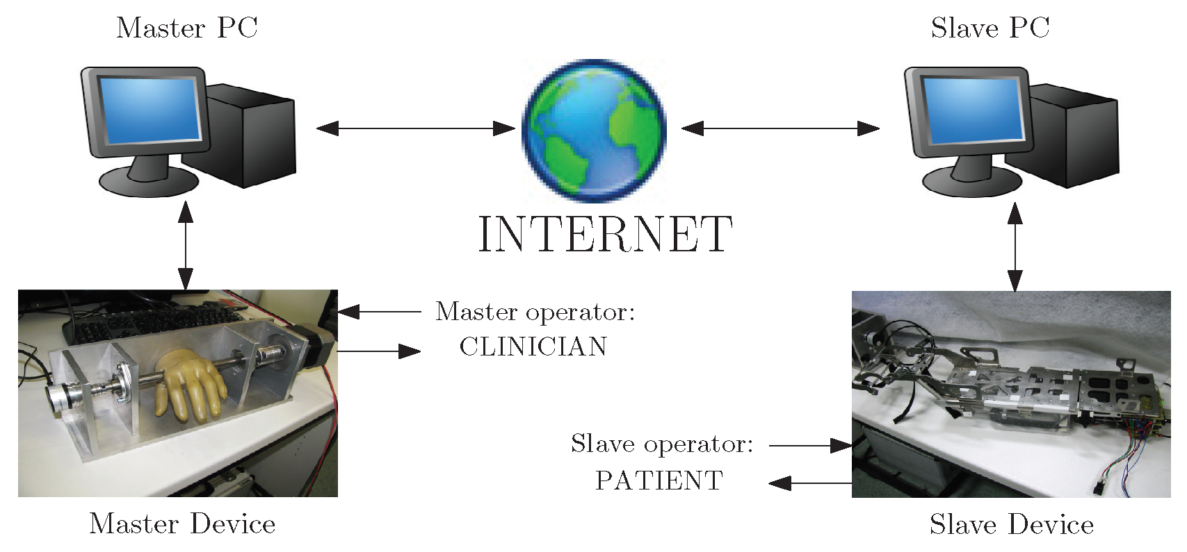
2. Specifications and System Description
2.1. Specifications
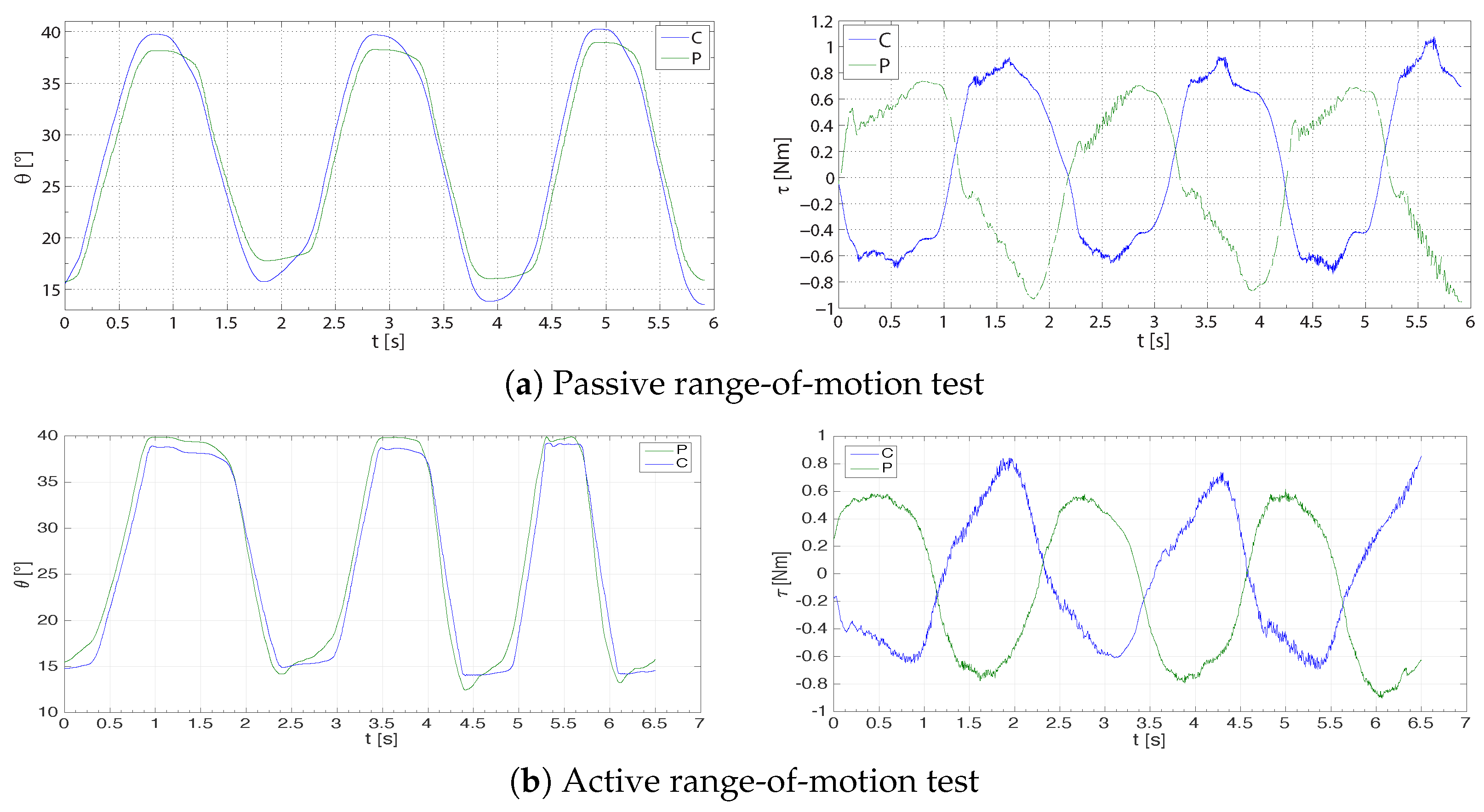
- Passive range of motion (ROM) test: at the beginning of the evaluating session, the clinician slowly moves the fingers on the patient’s hand (to minimize the potential-reflected response) to find the range of motion.
- Active ROM test: the patient is asked to move the fingers on the hand up to their moving limit.
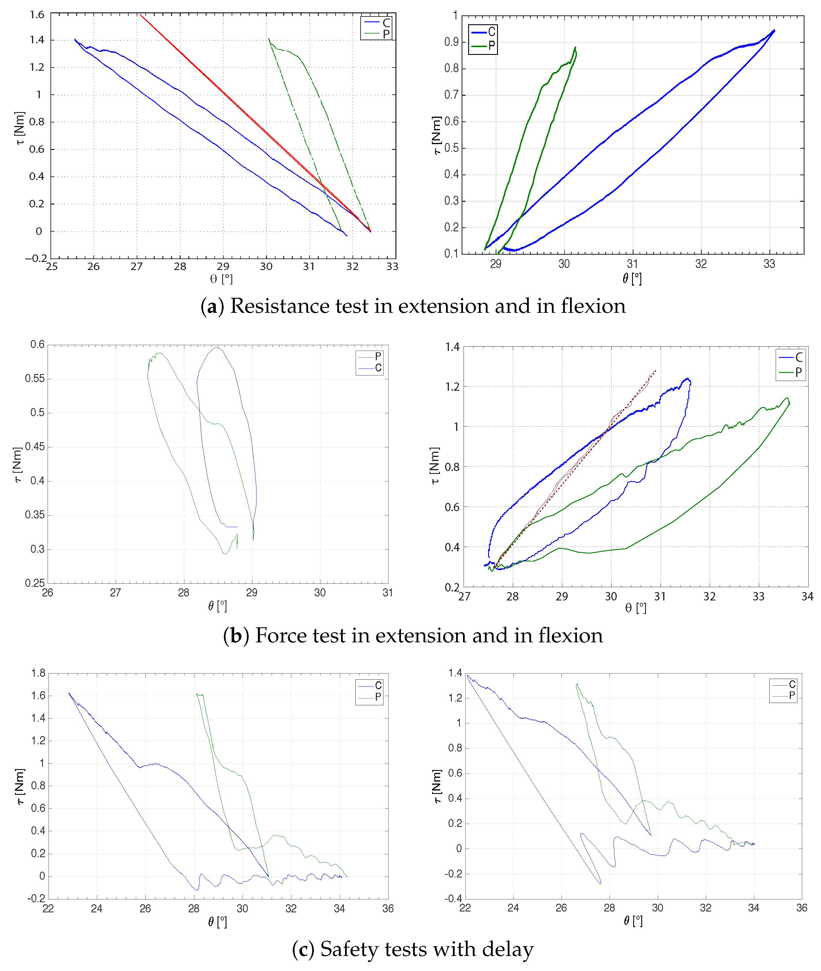
- Muscular resistance test: the patient is asked to keep the fingers on the hand fixed, while the clinician tries to either flex or extend them.
- Muscular force test: the patient is asked to either flex or extend the fingers on the hand, while the clinician tries to keep them blocked.
- Spasticity test with catch angle evaluation: the clinician holds the patient’s hand and moves their fingers at different velocities in order to feel the velocity-dependence of the resistance torque and the ‘catch’, defined as the angle at which the resistance to a movement abruptly grows.
- Patient’s hand position sent back to the master (ROM test);
- Fair reproduction of force (muscular/resistance test);
- Maximum transparency at each side;
- Stability in the presence of, at least, small network delays (standard ADSLin a limited range);
- Maximum versatility of the slave device, in order to guarantee an effective two-fold use of the active hand orthosis (remote assessment and rehabilitation).
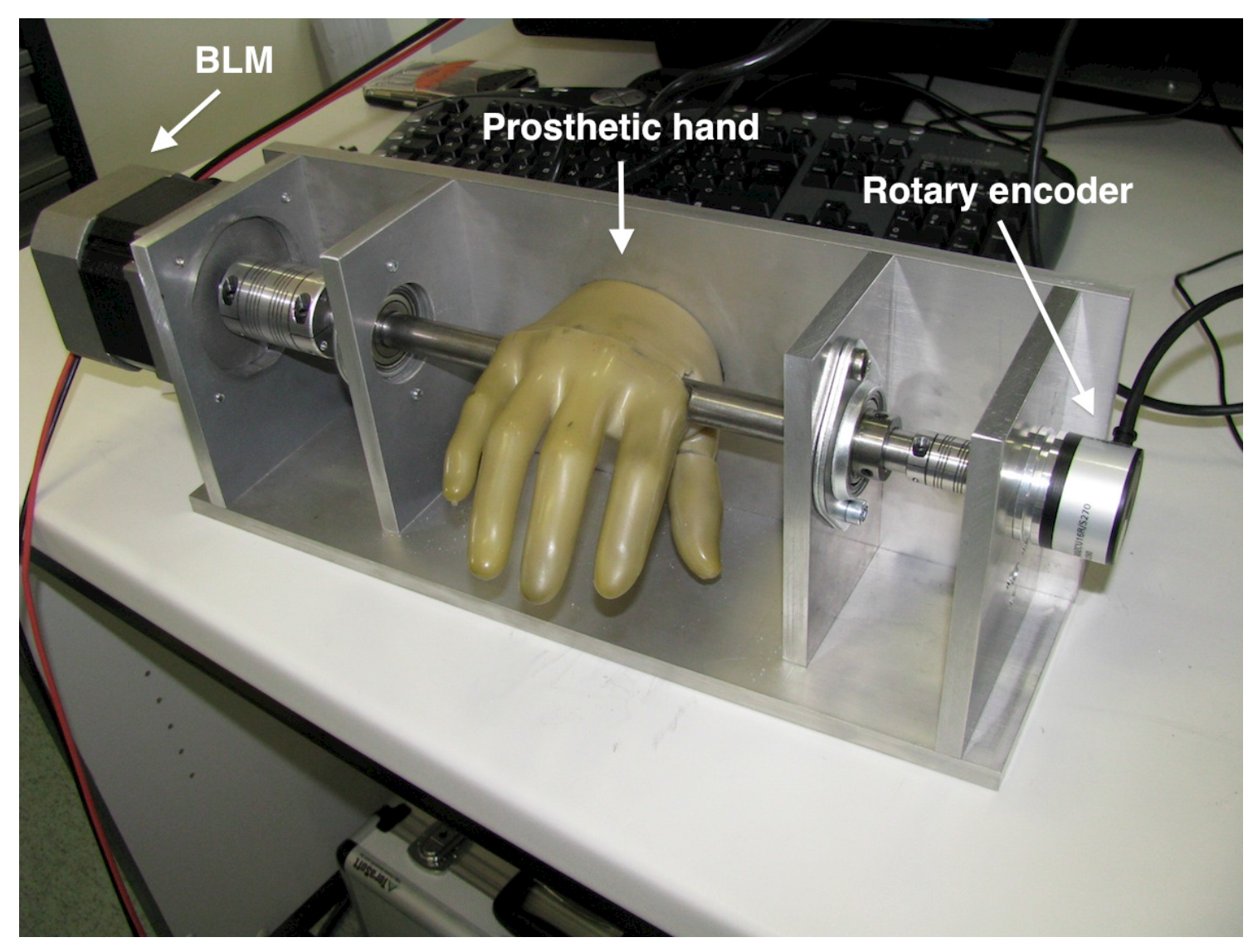
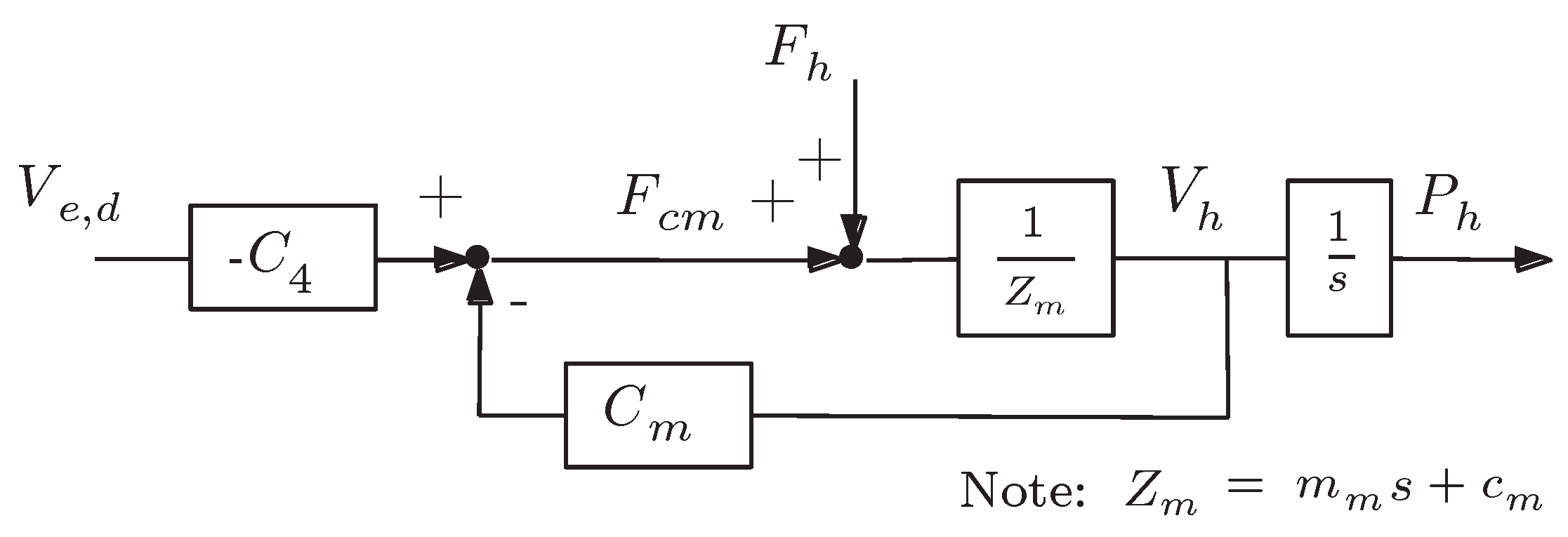
2.2. Master Device
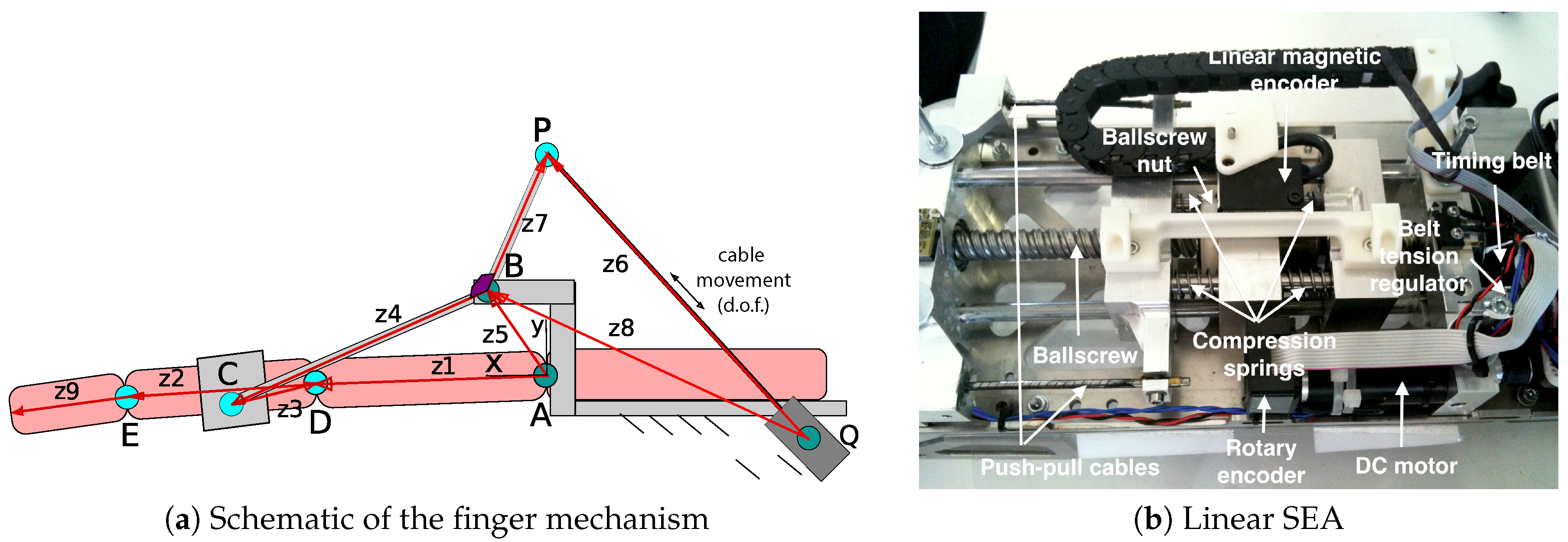
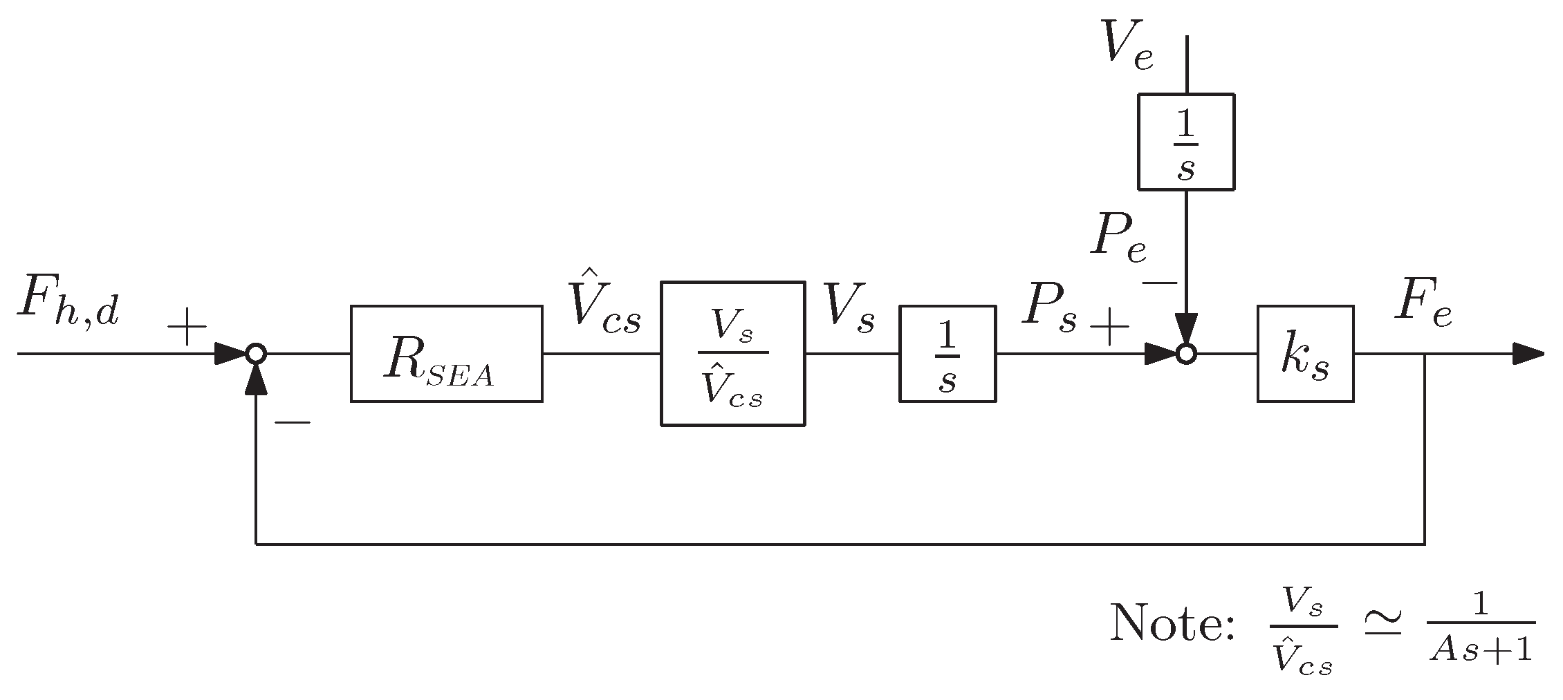
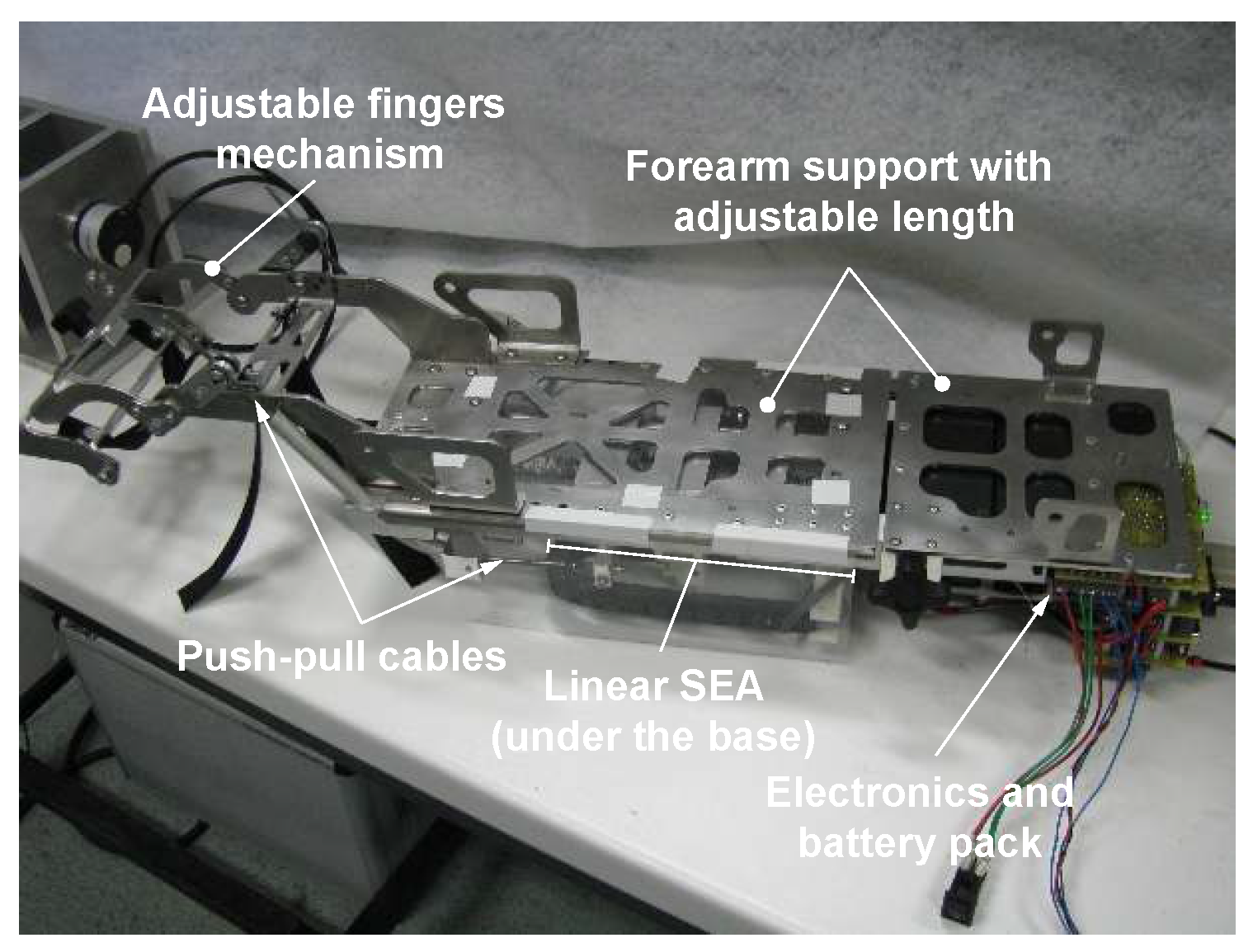
2.3. Slave Device with VS-SEA
2.4. Communication Line and Safety
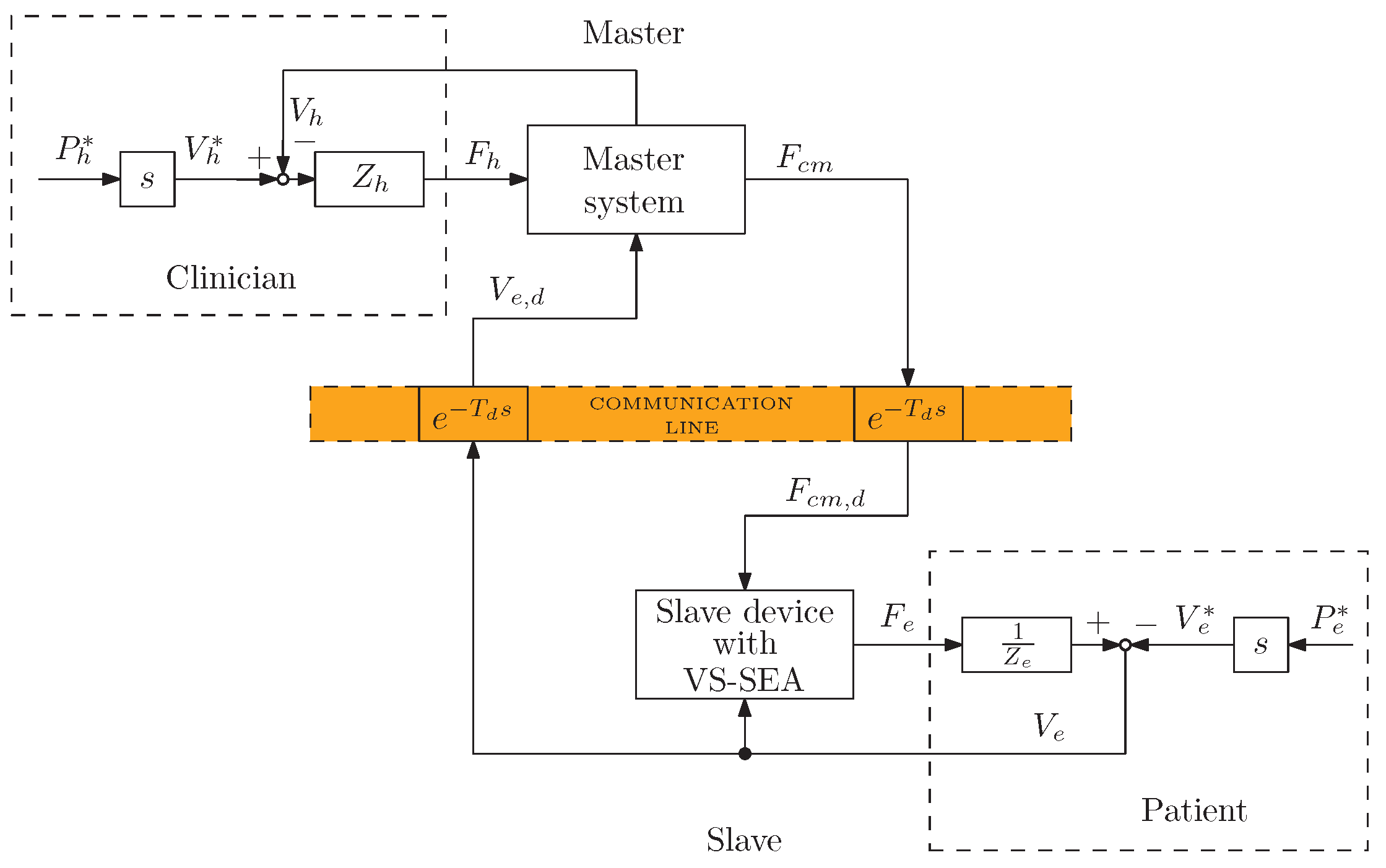
3. Control-System Design
3.1. Definition of the Control Architecture
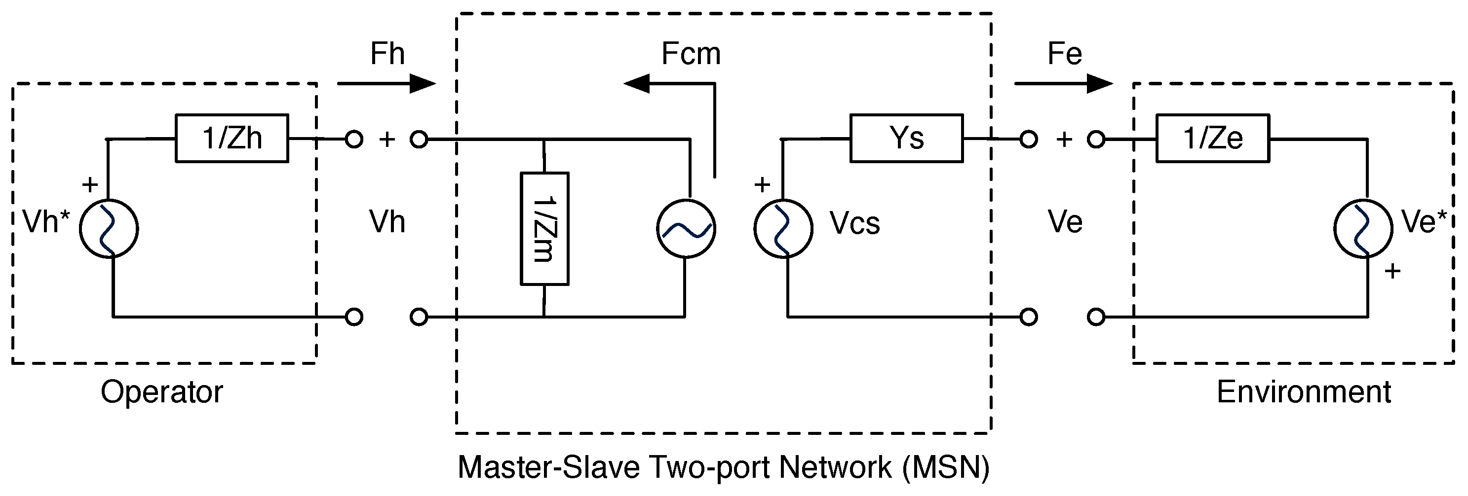
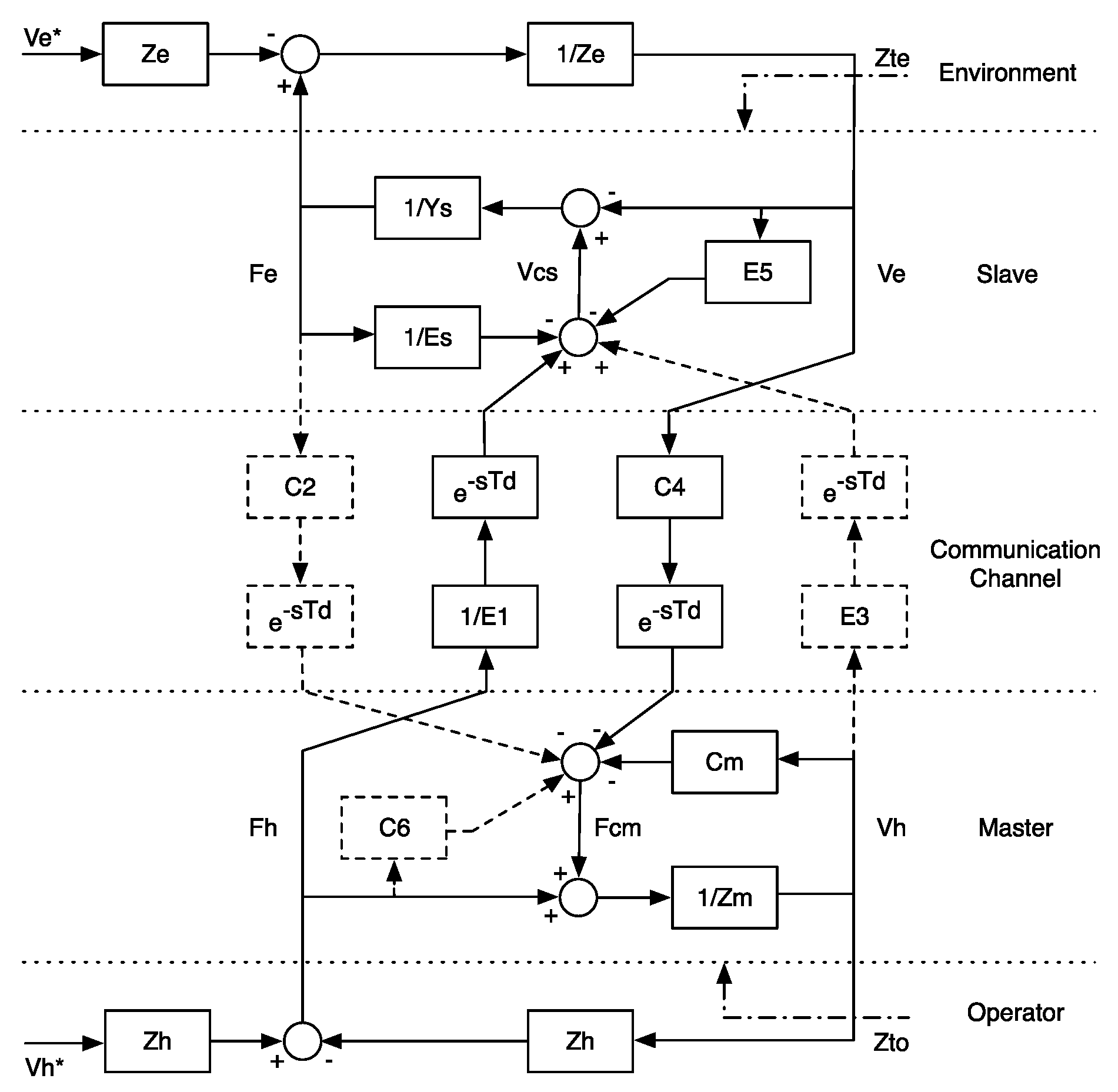
3.2. Control Design: Four-Channel and Two-Port Network Models
3.3. Definition of the Control Law
4. System Analysis
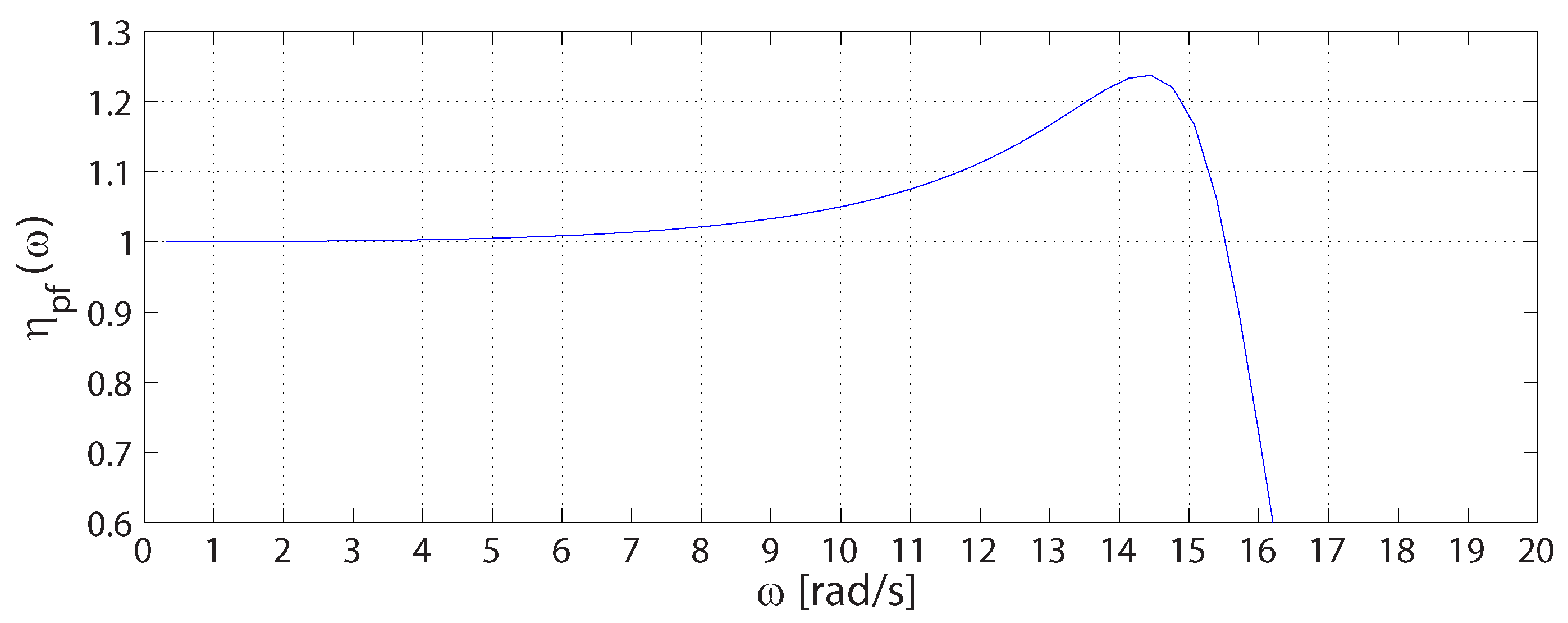
4.1. Transparency
4.2. Performance
4.3. Stability
- and have no poles in the open right half-plane (RHP)
- any pole of and on the imaginary axis are simple and have real positive residuals
- and
5. Preliminary Experimental Tests
5.1. Protocol
5.2. Results
5.2.1. Active and Passive Range-Of-Motion Tests
5.2.2. Muscular and Resistance Tests
5.2.3. Safety Tests and Maximum Perceived Stiffness
6. Conclusions
Author Contributions
Conflicts of Interest
References
- Writing Group Members; Roger, V.L.; Go, A.S.; Lloyd-Jones, D.M.; Benjamin, E.J.; Berry, J.D.; Borden, W.B.; Bravata, D.M.; Dai, S.; Ford, E.S.; et al. Heart disease and stroke statistics—2012 update: A report from the American Heart Association Statistics Committee and Stroke Statistics Subcommittee. Circulation 2012, 125, e2–e220. [Google Scholar] [PubMed]
- Masiero, S.; Celia, A.; Rosati, G.; Armani, M. Robotic-assisted rehabilitation of the upper limb after acute stroke. Arch. Phys. Med. Rehabil. 2007, 88, 142–149. [Google Scholar] [CrossRef] [PubMed]
- Oujamaa, L.; Relave, I.; Froger, J.; Mottet, D.; Pelissier, J.Y. Rehabilitation of arm function after stroke. Literature review. Ann. Phys. Rehabil. Med. 2009, 52, 269–293. [Google Scholar] [CrossRef] [PubMed]
- Timmermans, A.A.; Seelen, H.A.M.; Willmann, R.D.; Kingma, H. Technology-assisted training of arm-hand skills in stroke: Concepts on reacquisition of motor control and therapist guidelines for rehabilitation technology design. J. Neuroeng. Rehabil. 2009, 6, 1. [Google Scholar] [CrossRef] [PubMed]
- Rosati, G. The place of robotics in post-stroke rehabilitation. Expert Rev. Med. Devices 2010, 7, 753–758. [Google Scholar] [CrossRef] [PubMed]
- Harwin, S.; Patton, J.L.; Edgerton, V.R. Challenges and opportunities for robot-mediated neurorehabiltation. Proc. IEEE 2006, 94, 1717–1726. [Google Scholar] [CrossRef]
- Alamri, A.; Iglesias, R.; Eid, M.; Saddik, A.E.; Shirmohammadi, S.; Lemaire, E. Haptic exercises for measuring improvement of post-stroke rehabilitation patients. In Proceedings of the IEEE International Workshop on Medical Measurement and Applications, Warsaw, Poland, 4–5 May 2007; pp. 1–6.
- Rosati, G.; Oscari, F.; Pacchierotti, C.; Prattichizzo, D. Effects of kinesthetic and cutaneous stimulation during the learning of a viscous force field. IEEE Trans. Haptics 2014, 7, 251–263. [Google Scholar] [CrossRef] [PubMed]
- Rosati, G.; Oscari, F.; Reinkensmeyer, D.; Secoli, R.; Avanzini, S.; Spagnol, S.; Masiero, S. Improving robotics for neurorehabilitation: Enhancing engagement, performance, and learning with auditory feedback. In Proceedings of the 2011 IEEE International Conference on Rehabilitation Robotics (ICORR), Zurich, Switzerland, 29 June–1 July 2011.
- Rosati, G.; Oscari, F.; Spagnol, S.; Avanzini, F.; Masiero, S. Effect of task-related continuous auditory feedback during learning of tracking motion exercises. J. Neuroeng. Rehabil. 2012, 9, 79. [Google Scholar] [CrossRef] [PubMed]
- Oscari, F.; Secoli, R.; Avanzini, F.; Rosati, G.; Reinkensmeyer, D.J. Substituting auditory for visual feedback to adapt to altered dynamic and kinematic environments during reaching. Exp. Brain Res. 2012, 221, 33–41. [Google Scholar] [CrossRef] [PubMed]
- Outpatient Service Trialists. Therapy-based rehabilitation services for stroke patients at home. Cochrane Database Syst. Rev. 2003, 1, CD002925. [Google Scholar]
- Ghasemi, F. Developing a telerehabilitation system for Hand. Int. J. Inf. Educ. Technol. 2012, 2, 1–9. [Google Scholar]
- Durfee, W.; Carey, J.; Nuckley, D.; Deng, J. Design and implementation of a home stroke telerehabilitation system. In Proceedings of the 2009 Annual International Conference of the IEEE Engineering in Medicine and Biology Society, Minneapolis, MN, USA, 3–6 September 2009; pp. 2422–2425.
- Deakin, A.; Hill, H.; Pomeroy, V.M. Rough guide to the fugl-meyer assessment. Physiotherapy 2003, 89, 751–763. [Google Scholar] [CrossRef]
- Palmer, M.L.; Epler, M.E. Fundamentals of Musculoskeletal Assessment Techniques; Lippincott Williams and Wilkins: Philadelphia, PA, USA, 1998. [Google Scholar]
- Park, S.; Wu, Y.N.; Ren, Y.; Zhang, L.Q. A tele-assessment system for evaluating elbow spasticity in patients with neurological impairments. In Proceedings of the 2007 IEEE 10th International Conference on Rehabilitation Robotics, Noordwijk, The Netherlands, 13–15 June 2007; pp. 917–922.
- Park, H.S.; Ren, Y.; Zhang, L.Q. A portable telerehabilitation system for remote evaluations of impaired elbows in neurological disorders. IEEE Trans. Neural Syst. Rehabil. Eng. 2008, 16, 245–254. [Google Scholar] [CrossRef] [PubMed]
- Lanini, J.; Tsuji, T.; Wolf, P.; Riener, R.; Novak, D. Teleoperation of two six-degree-of-freedom arm rehabilitation exoskeletons. In Proceedings of the 2015 IEEE International Conference on Rehabilitation Robotics (ICORR), Singapore, 11–14 August 2015; pp. 514–519.
- Zhang, S.; Guo, S.; Gao, B.; Hirata, H.; Ishihara, H. Design of a novel telerehabilitation system with a force-sensing mechanism. Sensors 2015, 15, 11511–11527. [Google Scholar] [CrossRef] [PubMed]
- Chiri, A.; Cortese, M.; de Almeida Ribeiro, P.; Cempini, M.; Vitiello, N.; Soekadar, S.; Carrozza, M. A telerehabilitation system for hand functional training. In Converging Clinical and Engineering Research on Neurorehabilitationn; Springer: Berlin, Germany, 2013. [Google Scholar]
- Cortese, M.; Cempini, M.; de Almeida Ribeiro, P.; Soekadar, S.; Carrozza, M.; Vitiello, N. A mechatronic system for robot-mediated hand telerehabilitation. IEEE/ASME Trans. Mechatron. 2015, 20, 1753–1764. [Google Scholar] [CrossRef]
- Airò Farulla, G.; Pianu, D.; Cempini, M.; Cortese, M.; Russo, L.O.; Indaco, M.; Nerino, R.; Chimienti, A.; Oddo, C.M.; Vitiello, N. Vision-based pose estimation for robot-mediated hand telerehabilitation. Sensors 2016, 16, 208. [Google Scholar] [CrossRef] [PubMed]
- Duncan, P.W.; Zorowitz, R.; Bates, B.; Choi, J.Y.; Glasberg, J.J.; Graham, G.D.; Katz, R.C.; Lamberty, K.; Reker, D. Management of adult stroke rehabilitation care: A clinical practice guideline. Stroke 2005, 36, e100–e143. [Google Scholar] [CrossRef] [PubMed]
- Loureiro, R.C.V.; Harwin, W.S. Reach & grasp therapy design and control of a 9-DOF robotic. In Proceedings of the 2007 IEEE 10th International Conference on Rehabilitation Robotics, Noordwijk, The Netherlands, 12–15 June 2007.
- Takahashi, C.D.; Der-Yeghiaian, L.; Le, V.; Motiwala, R.R.; Cramer, S.C. Robot-based hand motor therapy after stroke. Brain 2008, 131, 425–437. [Google Scholar] [CrossRef] [PubMed]
- Ren, Y.; Park, H.S.; Zhang, L.Q. Developing a whole-arm exoskeleton robot with hand opening and closing mechanism for upper limb stroke rehabilitation. In Proceedings of the 2009 IEEE 11th International Conference on Rehabilitation Robotics, Kyoto, Japan, 23–26 June 2009.
- Rosati, G.; Cenci, S.; Boschetti, G.; Zanotto, D.; Masiero, S. Design of a single-dof active hand orthosis for neurorehabilitation. In Proceedings of the IEEE 11th International Conference on Rehabilitation Robotics, Kyoto, Japan, 23–26 June 2009; pp. 161–166.
- Robinson, W. Design and Analysis of Series Elasticity in Closed-Loop Actuator Force Control. Ph.D. Thesis, Department of Mechanical Engineering, Massachusetts Institute of Technology, Cambridge, MA, USA, 2000. [Google Scholar]
- Robinson, W.; Pratt, J.E.; Paluska, D.J.; Pratt, G.A. Series elastic actuator development for a biomimetic walking robot. In Proceedings of the IEEE/ASME International Conference on Advanced Intelligent Mechatronics, Atlanta, GA, USA, 19–23 September 1999; pp. 19–22.
- Krebs, H.I.; Hogan, N.; Aisen, M.L.; Volpe, B.T. Robot-aided neurorehabilitation. IEEE Trans. Rehabil. Eng. 1998, 6, 7587. [Google Scholar] [CrossRef]
- Pratt, G.A.; Willisson, P.; Bolton, C.; Hofman, A. Late motor processing in low-impedance robots: Impedance control of series elastic actuators. In Proceedings of American Control Conference, Boston, MA, USA, 30 June–2 July 2004.
- Wyeth, G. Demonstrating the safety and performance of a velocity sourced series elastic actuator. In Proceedings of the IEEE International Conference on Robotics and Automation, Pasadena, CA, USA, 19–23 May 2008; pp. 3642–3647.
- Oboe, R. Force-reflecting teleoperation over the internet: The JBIT project. Proc. IEEE 2003, 91, 449–462. [Google Scholar] [CrossRef]
- Oboe, R.; Daud, O.A.; Masiero, S.; Oscari, F.; Rosati, G. Development of a haptic teleoperation system for remote motor and functional evaluation of hand in patients with neurological impairments. In Proceedings of the 11th IEEE International Workshop on Advanced Motion Control, Niigata, Japan, 21–24 March 2010; pp. 518–523.
- Salcudean, S.E.; Vlaar, T.D. On the emulation of stiff walls and static friction with a magnetically levitated input/output device. J. Dyn. Syst. 1997, 119, 127–132. [Google Scholar] [CrossRef]
- Rossi, A.; Gallina, P.; Rosati, G.; Zanotto, V. Rate-to-force control in admittance mode bilateral teleoperation. In Proceeding of the 2004 the Eleventh World Congress in Mechanism and Machine Science, Tianjin, China, 1–4 April 2004; pp. 1373–1379.
- Raju, J.; Verghese, G.C.; Sheridan, T.B. Design Issues in 2-port network models of bilateral remote manipulation. In Proceedings of the IEEE International Conference on Robotics and Automation, Scottsdale, AZ, USA, 14–19 May 1989; pp. 1316–1321.
- Hannaford, B. A design framework for teleoperators with kinestethic feedback. IEEE Trans. Robot. Autom. 1989, 5, 426–434. [Google Scholar] [CrossRef]
- Lawrence, D.A. Stability and transparency in bilateral teleoperation. IEEE Trans. Robot. Autom. 1993, 9, 624–637. [Google Scholar] [CrossRef]
- Hashtrudi-Zaad, K.; Salcudean, S.E. Analisys of control architectures for teleoperation systems with impedance/admittance master and slave manipulators. Int. J. Robot. Res. 2001, 20, 419–445. [Google Scholar] [CrossRef]
- Wieneke, G.H.; van der Gon, J.J.D. Variations in the output impedance of the human motor system. Biol. Cybern. 1974, 15, 159–178. [Google Scholar] [CrossRef]
- Kazerooni, H.; Tsay, T.I.; Hollerbach, K. A controller design framework for telerobotic systems. IEEE Trans. Control Syst. Technol. 1993, 1, 50–62. [Google Scholar] [CrossRef]
- Parker, R.; Salcudean, S.E.; Lawrence, P.D. Application of force feedback to heavy duty hydraulic machines. In Proceedings of the IEEE International Conference on Robotics ans Automation, Tokyo, Japan, 2–6 May 1993; pp. 375–381.
- Adams, R.J.; Hannaford, B. Stable haptic interaction with virtual environments. IEEE Trans. Robot. Autom. 1999, 15, 465–474. [Google Scholar] [CrossRef]
- Williams, L.R.; Henry, J.M.; Murphy, M.A. Naturally-transitioning rate to force control in free and constrained motion. J. Dyn. Syst. Meas. Control 1999, 121, 425–432. [Google Scholar] [CrossRef]
- Haykin, S. Active Network Theory; Addison-Wesley Educational Publishers Inc.: Boston, MA, USA, 1970. [Google Scholar]
- Kapandji, I.A. The Physiology of the Joints: The Upper Limb: 1; Churchill Livingstone: London, UK, 2007. [Google Scholar]
- Astins, A.D. Finger Force Capability: Measurement and Prediction Using Anthropometric and Myoelectric Measures. Master’s Thesis, Virginia Polytechnic Institute and State University, Blacksburg, VA, USA, 1999. [Google Scholar]
- Boissy, P.; Bourbonnais, D.; Carlotti, M.M.; Gravel, D.; Arsenault, B.A. Maximal grip force in chronic stroke subjects and its relationship to global upper extremity function. Clin. Rehabil. 1999, 13, 354–362. [Google Scholar] [CrossRef] [PubMed]


| Master Parameters | Slave Parameters | ||||
|---|---|---|---|---|---|
| Par. | Units | Values | Par. | Units | Value |
| Nm/rad | Nm/rad | ||||
| Nm/(rad/s) | A | s | |||
| kgm | τ | s | |||
| Nm/(rad/s) | G | (rad/s)/Nm | |||
| Subj. | Passive ROM Test | Active ROM Test | ||||||||||
|---|---|---|---|---|---|---|---|---|---|---|---|---|
| Clinician ROM [] | Subject ROM [] | Clinician ROM [] | Subject ROM [] | |||||||||
| S1 | ||||||||||||
| S2 | ||||||||||||
| S3 | ||||||||||||
| Subj. | Resistance Test | Muscular Test | ||||||||||||||
|---|---|---|---|---|---|---|---|---|---|---|---|---|---|---|---|---|
| Extension Stiffness [Nm/rad] | Flexion Stiffness [Nm/rad] | Extension Stiffness [Nm/rad] | Flexion Stiffness [Nm/rad] | |||||||||||||
| Clinician | Subject | Clinician | Subject | Clinician | Subject | Clinician | Subject | |||||||||
| S1 | ||||||||||||||||
| S2 | ||||||||||||||||
| S3 | ||||||||||||||||
© 2016 by the authors; licensee MDPI, Basel, Switzerland. This article is an open access article distributed under the terms and conditions of the Creative Commons Attribution (CC-BY) license (http://creativecommons.org/licenses/by/4.0/).
Share and Cite
Oscari, F.; Oboe, R.; Daud Albasini, O.A.; Masiero, S.; Rosati, G. Design and Construction of a Bilateral Haptic System for the Remote Assessment of the Stiffness and Range of Motion of the Hand. Sensors 2016, 16, 1633. https://doi.org/10.3390/s16101633
Oscari F, Oboe R, Daud Albasini OA, Masiero S, Rosati G. Design and Construction of a Bilateral Haptic System for the Remote Assessment of the Stiffness and Range of Motion of the Hand. Sensors. 2016; 16(10):1633. https://doi.org/10.3390/s16101633
Chicago/Turabian StyleOscari, Fabio, Roberto Oboe, Omar Andres Daud Albasini, Stefano Masiero, and Giulio Rosati. 2016. "Design and Construction of a Bilateral Haptic System for the Remote Assessment of the Stiffness and Range of Motion of the Hand" Sensors 16, no. 10: 1633. https://doi.org/10.3390/s16101633
APA StyleOscari, F., Oboe, R., Daud Albasini, O. A., Masiero, S., & Rosati, G. (2016). Design and Construction of a Bilateral Haptic System for the Remote Assessment of the Stiffness and Range of Motion of the Hand. Sensors, 16(10), 1633. https://doi.org/10.3390/s16101633