
Afocal Optical Flow Sensor for Reducing Vertical Height Sensitivity in Indoor Robot Localization and Navigation


Abstract
:
1. Introduction
2. Methods
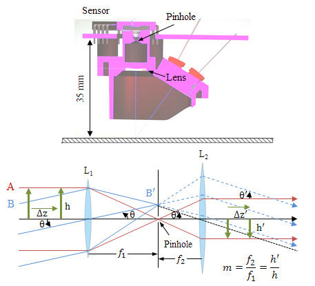
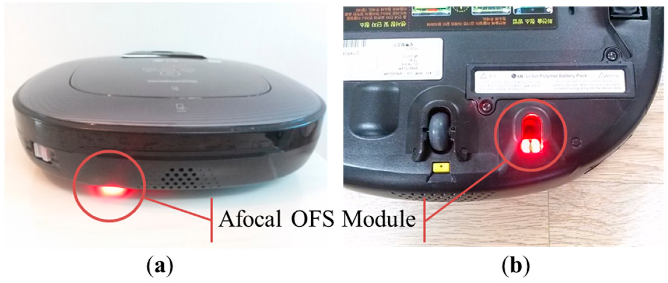
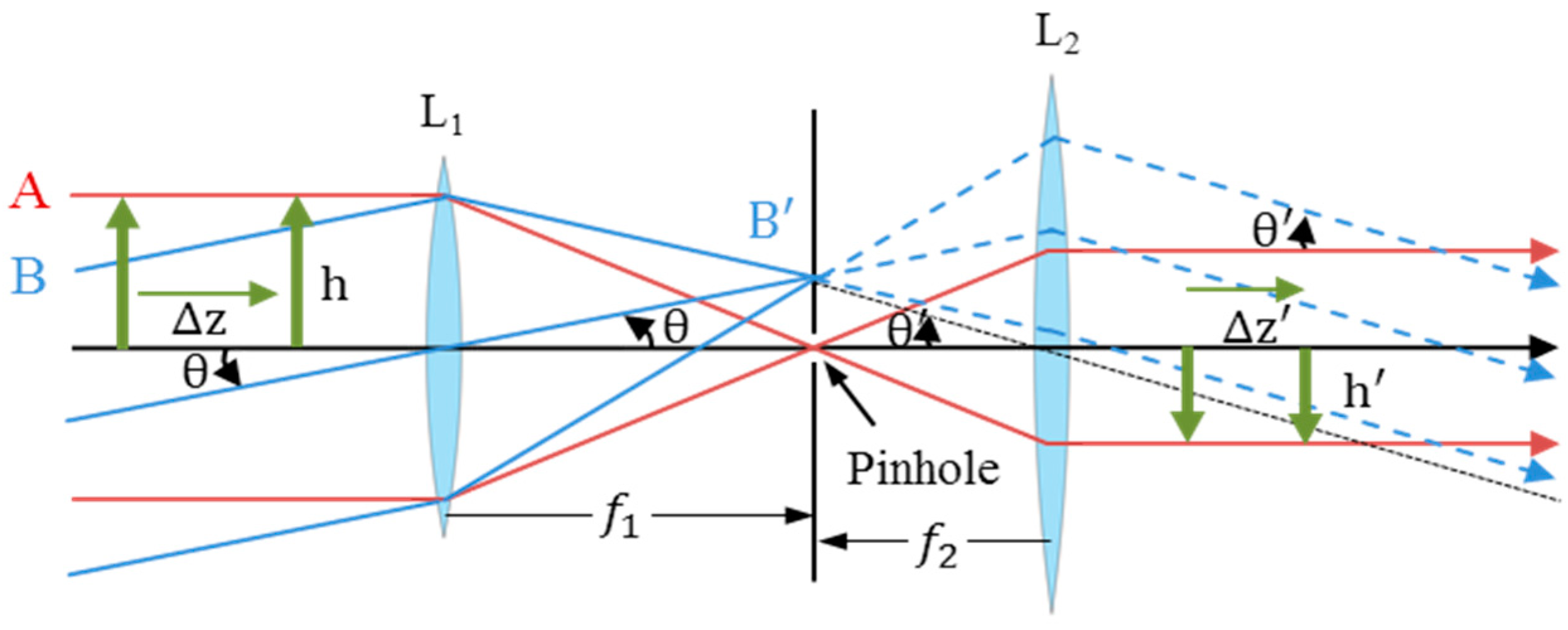
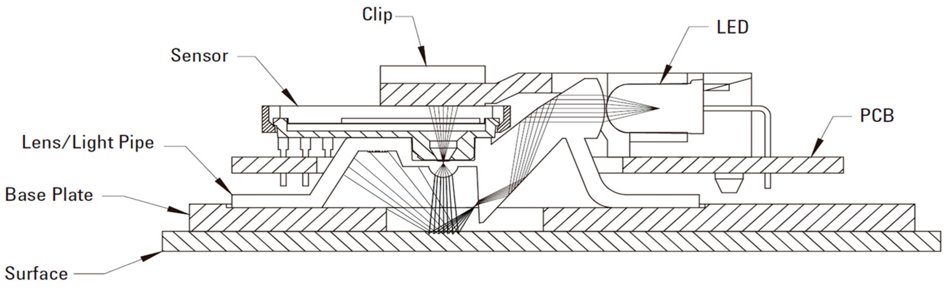
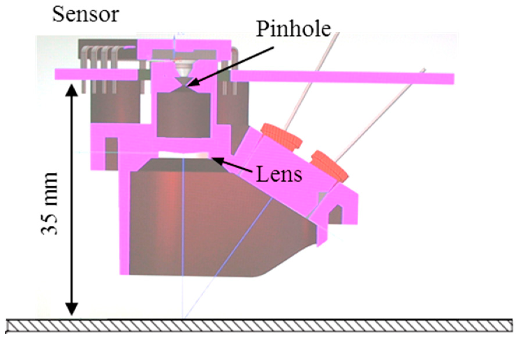
2.1. Afocal Optical Flow Sensor System


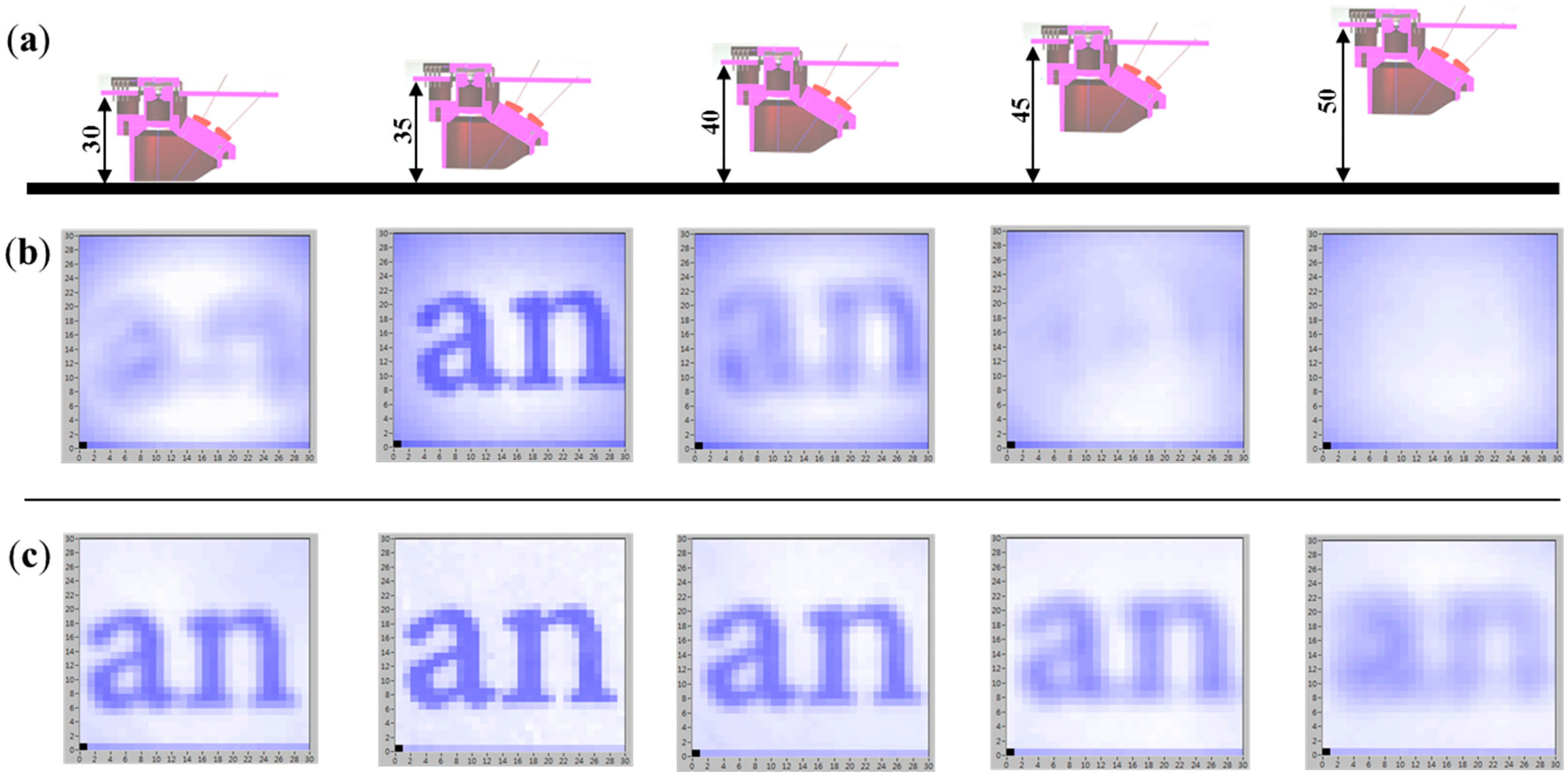
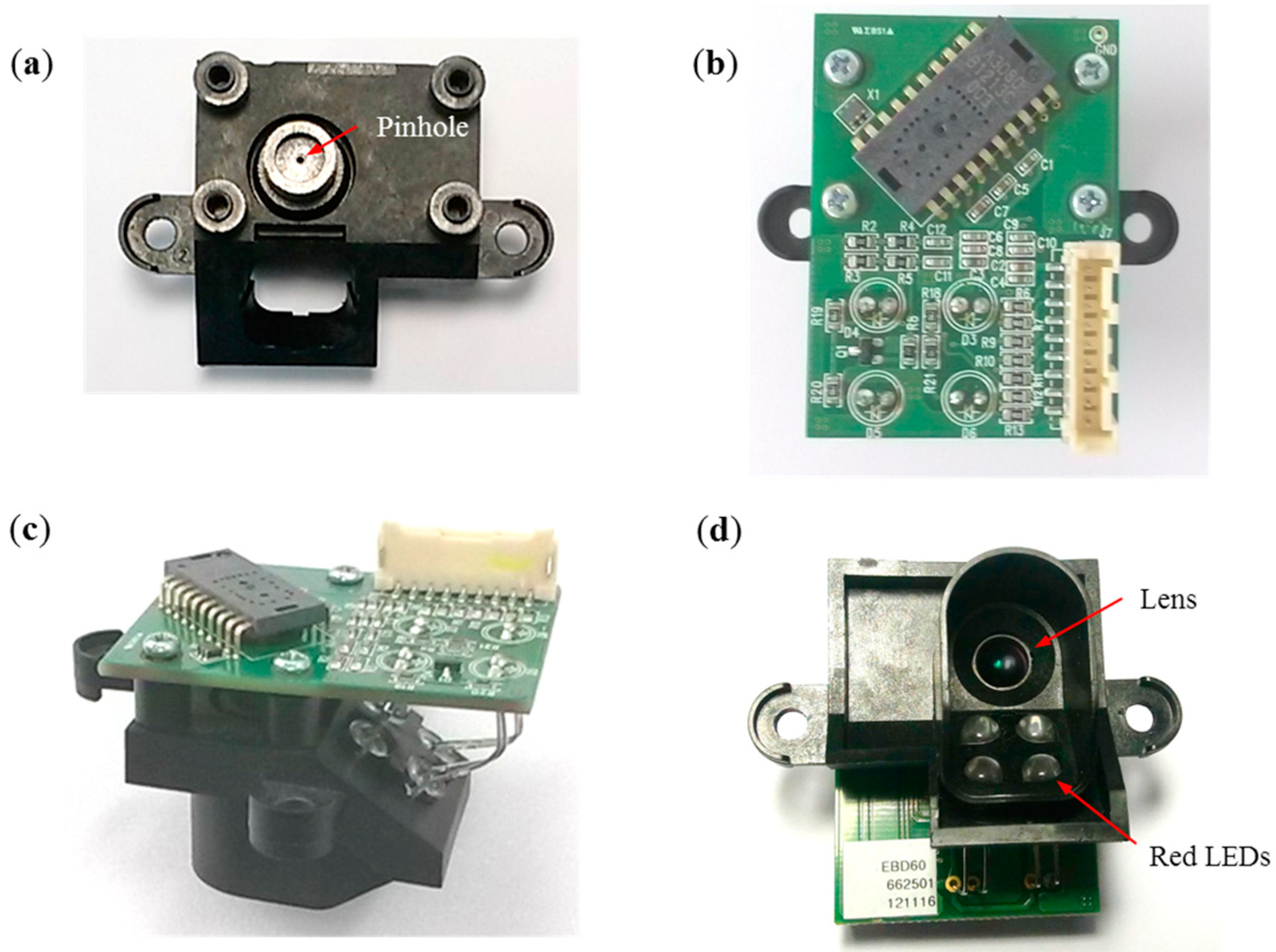
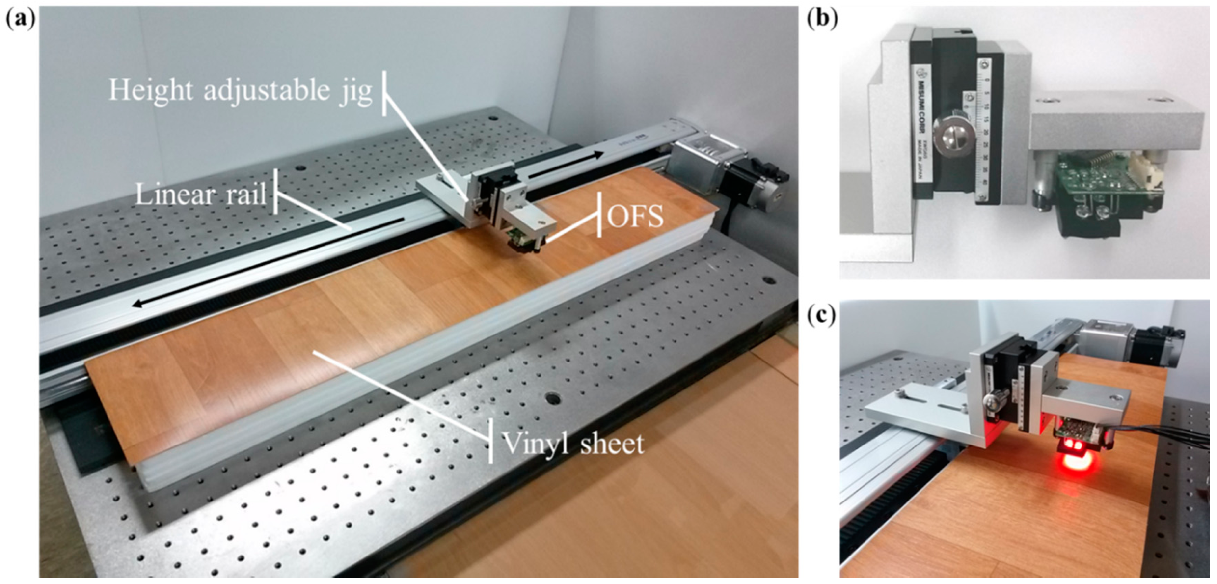
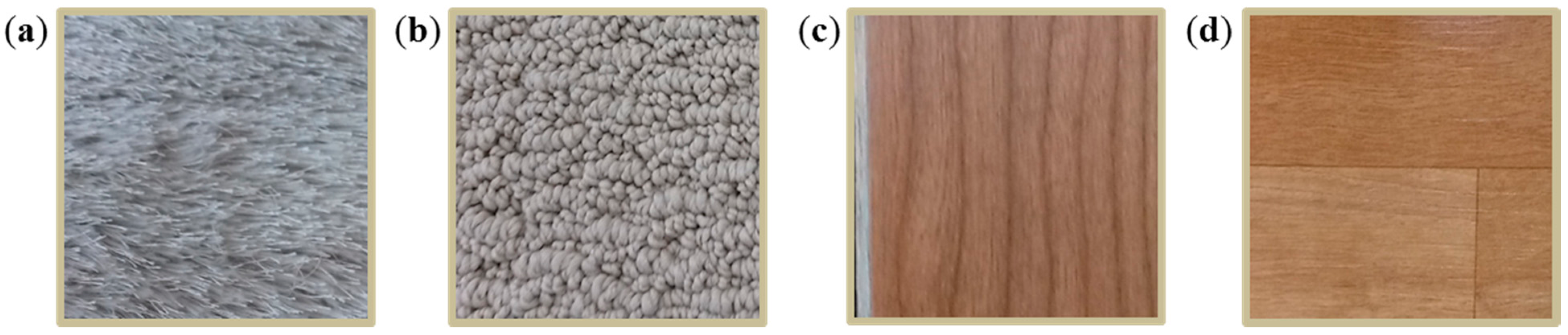
2.2. Experimental Setup


3. Results and Discussion


| Floor Material | Height (mm) | Conventional Fixed-Focal-Length OFS Module | Proposed Afocal OFS Module | ||||
|---|---|---|---|---|---|---|---|
| Mean (mm) | Standard Deviation | Error (%) | Mean (mm) | Standard Deviation | Error (%) | ||
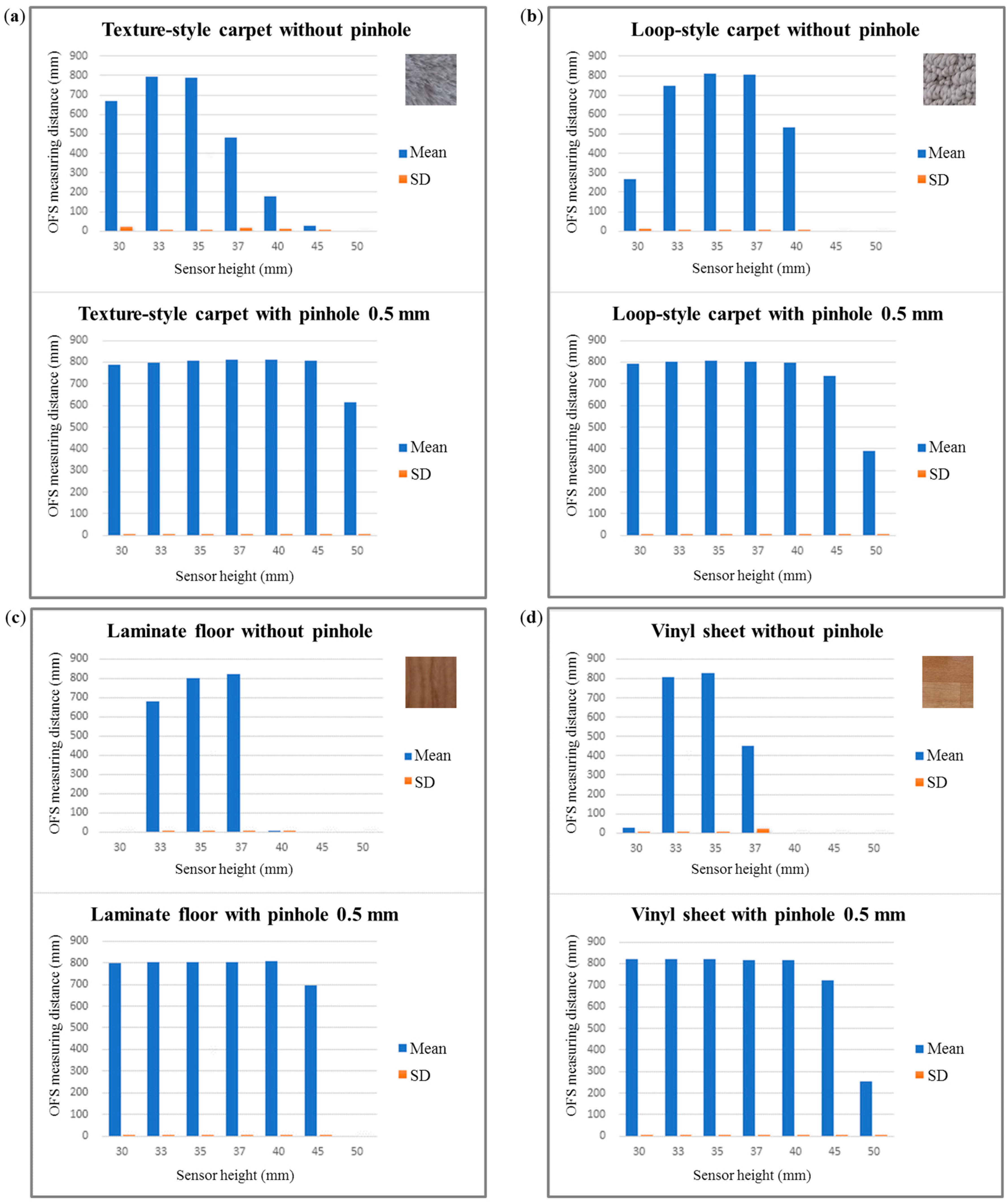
| Laminate Floor | 30 | 0 | 0 | 100.0 | 799 | 0.9 | 0.1 |
| 33 | 678 | 2.9 | 15.3 | 802 | 0.9 | 0.2 | |
| 35 | 802 | 0.4 | 0.3 | 804 | 0.8 | 0.5 | |
| 37 | 823 | 0.7 | 2.9 | 805 | 0.7 | 0.6 | |
| 40 | 8 | 1.4 | 99.0 | 806 | 0.5 | 0.8 | |
| 45 | 0 | 0 | 100.0 | 694 | 2.9 | 13.3 | |
| 50 | 0 | 0 | 100.0 | 0 | 0.0 | 100.0 | |
| Vinyl Sheet | 30 | 29 | 2.4 | 96.4 | 820 | 0.4 | 2.5 |
| 33 | 809 | 2.2 | 1.1 | 820 | 0.5 | 2.5 | |
| 35 | 827 | 0.6 | 3.4 | 820 | 0.6 | 2.5 | |
| 37 | 452 | 22.1 | 43.5 | 819 | 0.7 | 2.3 | |
| 40 | 0 | 0 | 100.0 | 817 | 0.7 | 2.1 | |
| 45 | 0 | 0 | 100.0 | 722 | 2.4 | 9.8 | |
| 50 | 0 | 0 | 100.0 | 253 | 2.4 | 68.4 | |
| Texture-Style Carpet | 30 | 671 | 20.6 | 16.1 | 789 | 2.6 | 1.4 |
| 33 | 796 | 6.5 | 0.5 | 799 | 1.6 | 0.2 | |
| 35 | 790 | 6.8 | 1.3 | 808 | 0.6 | 1.0 | |
| 37 | 482 | 18.3 | 39.8 | 810 | 0.6 | 1.3 | |
| 40 | 179 | 9.1 | 77.6 | 812 | 0.5 | 1.5 | |
| 45 | 28 | 4.7 | 96.5 | 807 | 1.5 | 0.9 | |
| 50 | 0 | 0 | 100.0 | 614 | 4.4 | 23.3 | |
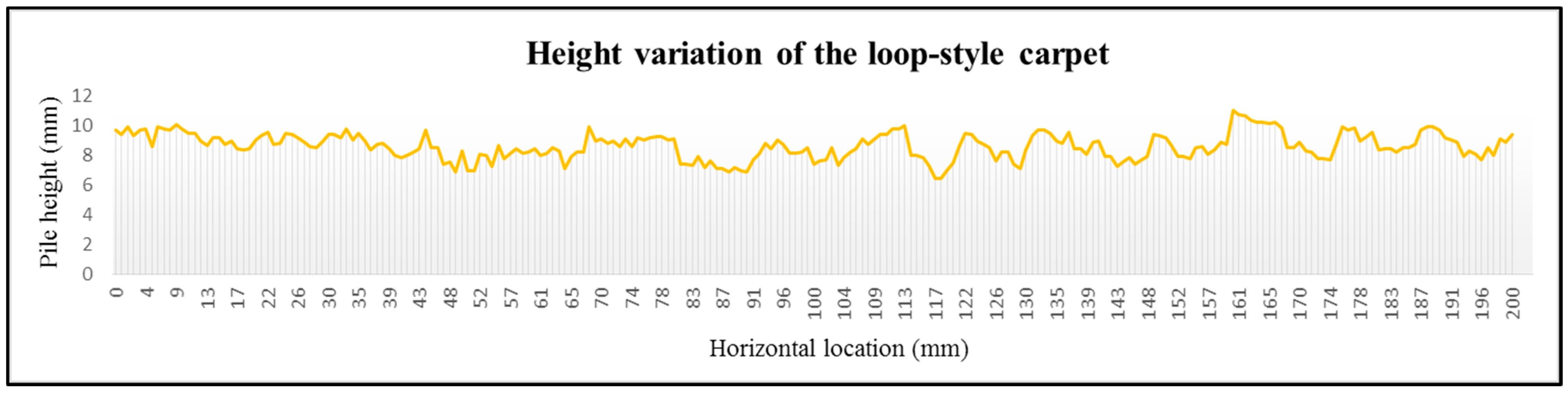
| Loop-Style Carpet | 30 | 267 | 9.5 | 66.6 | 794 | 0.5 | 0.8 |
| 33 | 749 | 2.3 | 6.4 | 802 | 0.4 | 0.2 | |
| 35 | 810 | 0.3 | 1.3 | 809 | 0.3 | 1.1 | |
| 37 | 803 | 1.6 | 0.4 | 804 | 0.5 | 0.4 | |
| 40 | 532 | 3.4 | 33.5 | 798 | 0.6 | 0.3 | |
| 45 | 0 | 0 | 100.0 | 737 | 1.8 | 7.9 | |
| 50 | 0 | 0 | 100.0 | 390 | 5.9 | 51.3 | |
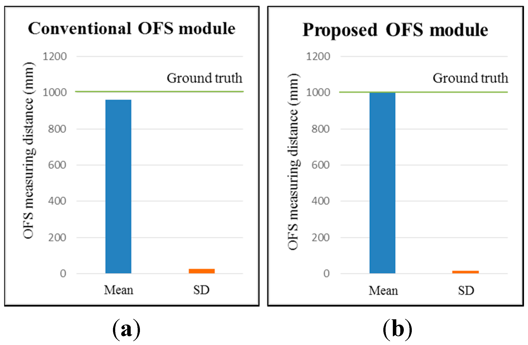
| Conventional Fixed-Focal-Length OFS Module | Proposed Afocal OFS Module | ||||
|---|---|---|---|---|---|
| Mean (mm) | Standard Deviation | Error (%) | Mean (mm) | Standard Deviation | Error (%) |
| 959.1 | 25.7 | 4.09 | 1000.2 | 17.6 | 0.02 |
4. Conclusions
Acknowledgments
Author Contributions
Conflicts of Interest
References
- Ishigami, G.; Nagatani, K.; Yoshida, K. Path planning for planetary exploration rovers and its evaluation based on wheel slip dynamics. In Proceedings of the 2007 IEEE International Conference on Robotics and Automation, Roma, Italy, 10–14 April 2007; pp. 2361–2366.
- Borenstein, J.; Everett, H.R.; Feng, L.; Wehe, D. Mobile robot positioning-sensors and techniques. J. Robot. Sys. 1997, 14, 231–249. [Google Scholar] [CrossRef]
- Munguia, R.; Castillo-Toledo, B.; Grau, A. A robust approach for a filter-based monocular simultaneous localization and mapping (SLAM) system. Sensors 2013, 13, 8501–8522. [Google Scholar] [CrossRef] [PubMed]
- Li, I.H.; Chen, M.C.; Wang, W.Y.; Su, S.F.; Lai, T.W. Mobile robot self-localization system using single webcam distance measurement technology in indoor environments. Sensors 2014, 14, 2089–2109. [Google Scholar] [CrossRef] [PubMed]
- Lee, D.; Myung, H. Solution to the SLAM problem in low dynamic environments using a pose graph and an RGB-D sensor. Sensors 2014, 14, 12467–12496. [Google Scholar] [CrossRef] [PubMed]
- Guerra, E.; Munguia, R.; Grau, A. Monocular SLAM for autonomous robots with enhanced features initialization. Sensors 2014, 14, 6317–6337. [Google Scholar] [CrossRef] [PubMed]
- McCarthy, C.; Bames, N. Performance of optical flow techniques for indoor navigation with a mobile robot. In Proceedings of the 2004 IEEE International Conference on Robotics and Automation, New Orleans, LA, USA, 26 April–1 May 2004; pp. 5093–5098.
- Campbell, J.; Sukthankar, R.; Nourbakhsh, I. Techniques for evaluating optical flow for visual odometry in extreme terrain. In Proceedings of the 2004 IEEE/RSJ International Conference on Intelligent Robots and Systems, Sendai, Japan, 28 September–2 October 2004; pp. 3704–3711.
- Nagatani, K.; Tachibana, S.; Sofne, M.; Tanaka, Y. Improvement of odometry for omnidirectional vehicle using optical flow information. In Proceedings of the 2000 IEEE/RSJ International Conference on the Intelligent Robots and Systems, Takamatsu, Japan, 30 October–5 November 2000; pp. 468–473.
- Jackson, J.D.; Callahan, D.W.; Marstrander, J. A rationale for the use of optical mice chips for economic and accurate vehicle tracking. In Proceedings of the 2007 IEEE International Conference on Automation Science and Engineering, Scottsdale, AZ, USA, 22–25 September 2007; pp. 939–944.
- Ng, T. The optical mouse as a two-dimensional displacement sensor. Sens. Actuators A Phys. 2003, 107, 21–25. [Google Scholar] [CrossRef]
- Lee, S.; Song, J. Mobile robot localization using optical flow sensors. Int. J. Control Autom. Syst. 2004, 2, 485–493. [Google Scholar]
- Palacin, J.; Valganon, I.; Pernia, R. The optical mouse for indoor mobile robot odometry measurement. Sens. Actuators A Phys. 2006, 126, 141–147. [Google Scholar] [CrossRef]
- Bonarini, A.; Matteucci, M.; Restelli, M. A kinematic-independent dead-reckoning sensor for indoor mobile robotics. In Proceedings of the 2004 IEEE/RSJ International Conference on Intelligent Robots and Systems, Sendai, Japan, 28 September–2 October 2004; pp. 3750–3755.
- Bonarini, A.; Matteucci, M.; Restelli, M. Automatic error detection and reduction for an odometric sensor based on two optical mice. In Proceedings of the 2005 IEEE International Conference on Robotics and Automation, Barcelona, Spain, 18–22 April 2005; pp. 1675–1680.
- Sekimori, D.; Miyazaki, F. Self-localization for indoor mobile robots based on optical mouse sensor values and simple global camera information. In Proceedings of the 2005 IEEE International Conference on Robotics and Biomimetics, Hong Kong SAR and Macau SAR, 29 June–3 July 2005; pp. 605–610.
- Minoni, U.; Signorini, A. Low-cost optical motion sensors: An experimental characterization. Sens. Actuators A Phys. 2006, 128, 402–408. [Google Scholar] [CrossRef]
- Bradshaw, J.; Lollini, C.; Bishop, B. On the development of an enhanced optical mouse sensor for odometry and mobile robotics education. In Proceedings of the Thirty-Ninth Southeastern Symposium on System Theory, Macon, GA, USA, 4–6 March 2007; pp. 6–10.
- Kim, S.; Lee, S. Robust velocity estimation of an omnidirectional mobile robot using a polygonal array of optical mice. Int. J. Control Autom. Syst. 2008, 6, 713–721. [Google Scholar]
- Avago. ADNS-3080 and ADNS-3088 High Performance Optical Sensor. Available online: http://www.alldatasheet.com (accessed on 5 February 2015).
- Cooney, J.; Xu, W.; Bright, G. Visual dead-reckoning for motion control of a Mecanum-wheeled mobile robot. Mechatronics 2004, 14, 623–637. [Google Scholar] [CrossRef]
- Tunwattana, N.; Roskilly, A.; Norman, R. Investigations into the effects of illumination and acceleration on optical mouse sensors as contact-free 2D measurement devices. Sens. Actuators A Phys. 2009, 149, 87–92. [Google Scholar] [CrossRef]
- Ross, R.; Devlin, J. Analysis of real-time velocity compensation for outdoor optical mouse sensor odometry. In Proceedings of the 2010 11th International Conference on Control Automation Robotics & Vision, Singapore, 7–10 December 2010; pp. 839–843.
- Ross, R.; Devlin, J.; Wang, S. Toward Refocused Optical Mouse Sensors for Outdoor Optical Flow Odometry. IEEE Sens. J. 2012, 12, 1925–1932. [Google Scholar] [CrossRef]
- Dahmen, H.; Mallot, H.A. Odometry for Ground Moving Agents by Optic Flow Recorded with Optical Mouse Chips. Sensors 2014, 14, 21045–21064. [Google Scholar] [CrossRef] [PubMed]
- Font, D.; Tresanchez, M.; Palleja, T.; Teixido, M.; Palacin, J. Characterization of a Low-Cost Optical Flow Sensor When Using an External Laser as a Direct Illumination Source. Sensors 2011, 11, 11856–11870. [Google Scholar] [CrossRef] [PubMed]
- Dille, M.; Grocholsky, B.; Singh, S. Outdoor downward-facing optical flow odometry with commodity sensors. In Field and Service Robotics; Springer: Berlin, Germany, 2010; pp. 183–193. [Google Scholar]
- Hyun, D.; Yang, H.S.; Park, H.R.; Park, H.-S. Differential optical navigation sensor for mobile robots. Sens. Actuators A Phys. 2009, 156, 296–301. [Google Scholar] [CrossRef]
- John, E.G. Field Guide to Geometrical Optics; SPIE Press: Bellingham, WA, USA, 2004. [Google Scholar]
- Avago. Optical Mice and How They Work. Available online: http://www.digikey.com (accessed on 5 February 2015).
- Siah, T.H.; Kong, H.Y. Optical Navigation Using One-Dimensional Correlation. U.S. Patent 731,501,3, January 2008. [Google Scholar]
- Hu, J.-S.; Chang, Y.-J.; Hsu, Y.-L. Calibration and on-line data selection of multiple optical flow sensors for odometry applications. Sens. Actuators A Phys. 2009, 149, 74–80. [Google Scholar] [CrossRef]
- Mensov, S.N.; Lee, H.Y.; Kim, S.W.; Yi, D.H.; Yoon, J.S.; Yoon, H.W.; Park, D.W.; Cho, M.J. Sensor System and Position Recognition System. Korean Patent Registration No. 101304948, March 2008. [Google Scholar]
- Dream Robot System. DRSB90. Available online: http://www.drs11.co.kr (accessed on 5 February 2015).
- MiSUMi. XWG60. Available online: http://www.misumi-ec.com (accessed on 6 February 2015).
- Microchip. dsPIC33FJ256MC710A. Available online: http://www.microchip.com (accessed on 6 February 2015).
- DIMETIX. DLS-B 30. Available online: http://www.dimetix.com (accessed on 9 April 2015).
© 2015 by the authors; licensee MDPI, Basel, Switzerland. This article is an open access article distributed under the terms and conditions of the Creative Commons Attribution license (http://creativecommons.org/licenses/by/4.0/).
Share and Cite
Yi, D.-H.; Lee, T.-J.; Cho, D.-I. Afocal Optical Flow Sensor for Reducing Vertical Height Sensitivity in Indoor Robot Localization and Navigation. Sensors 2015, 15, 11208-11221. https://doi.org/10.3390/s150511208
Yi D-H, Lee T-J, Cho D-I. Afocal Optical Flow Sensor for Reducing Vertical Height Sensitivity in Indoor Robot Localization and Navigation. Sensors. 2015; 15(5):11208-11221. https://doi.org/10.3390/s150511208
Chicago/Turabian StyleYi, Dong-Hoon, Tae-Jae Lee, and Dong-Il Cho. 2015. "Afocal Optical Flow Sensor for Reducing Vertical Height Sensitivity in Indoor Robot Localization and Navigation" Sensors 15, no. 5: 11208-11221. https://doi.org/10.3390/s150511208
APA StyleYi, D.-H., Lee, T.-J., & Cho, D.-I. (2015). Afocal Optical Flow Sensor for Reducing Vertical Height Sensitivity in Indoor Robot Localization and Navigation. Sensors, 15(5), 11208-11221. https://doi.org/10.3390/s150511208