
Gait Measurement System for the Multi-Target Stepping Task Using a Laser Range Sensor


Abstract
:1. Introduction
2. Gait Measurement System
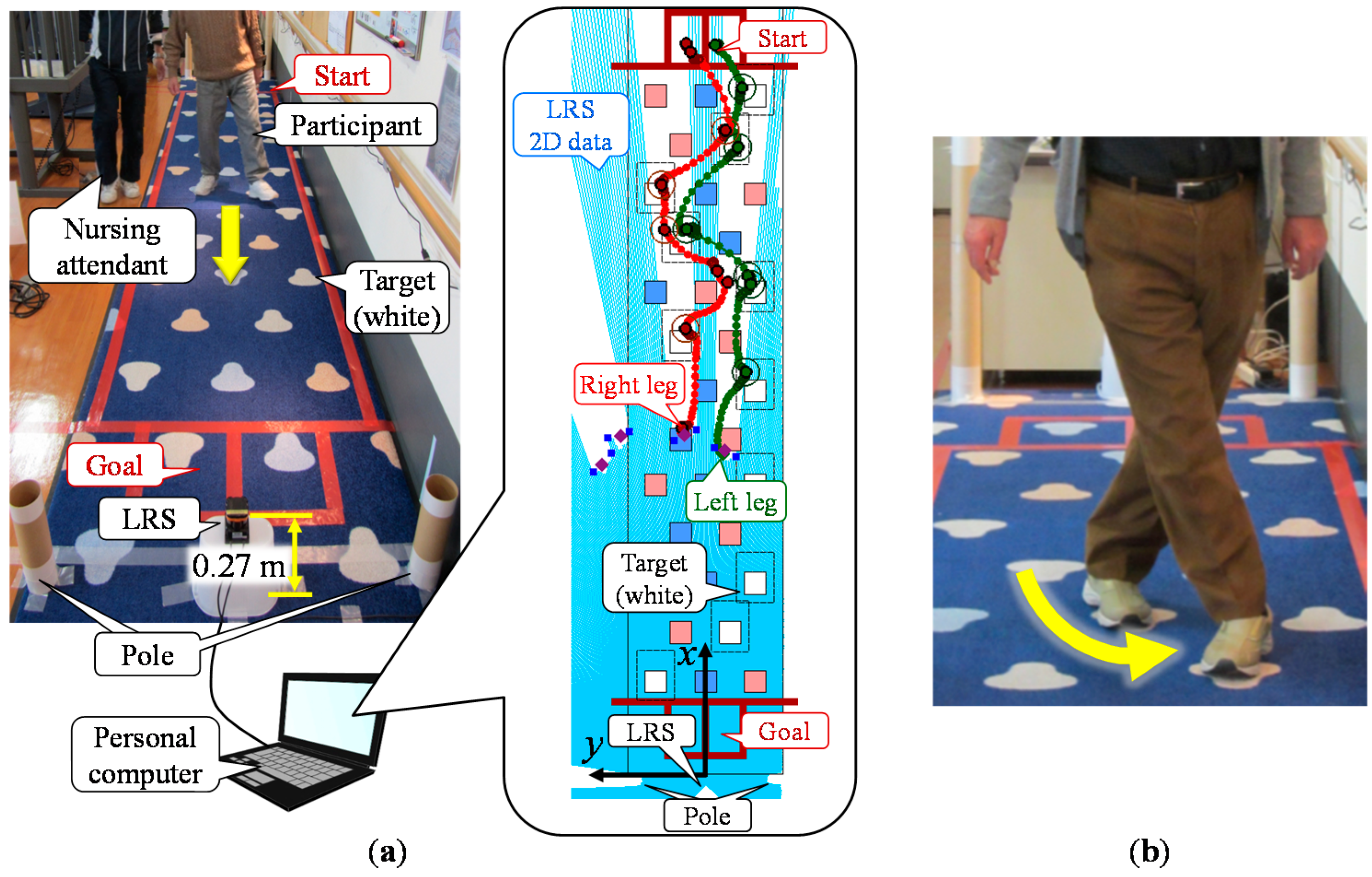
2.1. Configuration
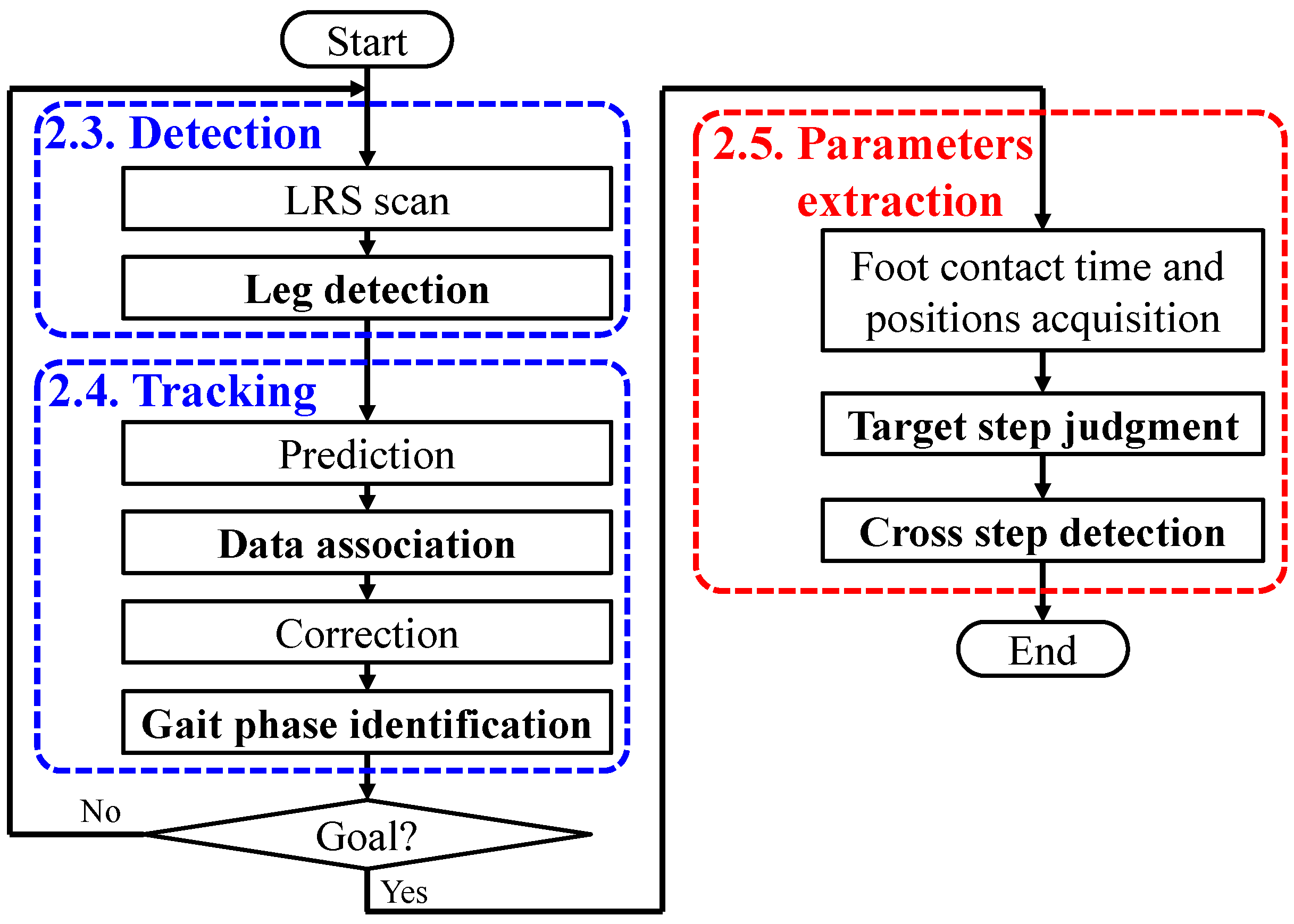
2.2. Algorithm

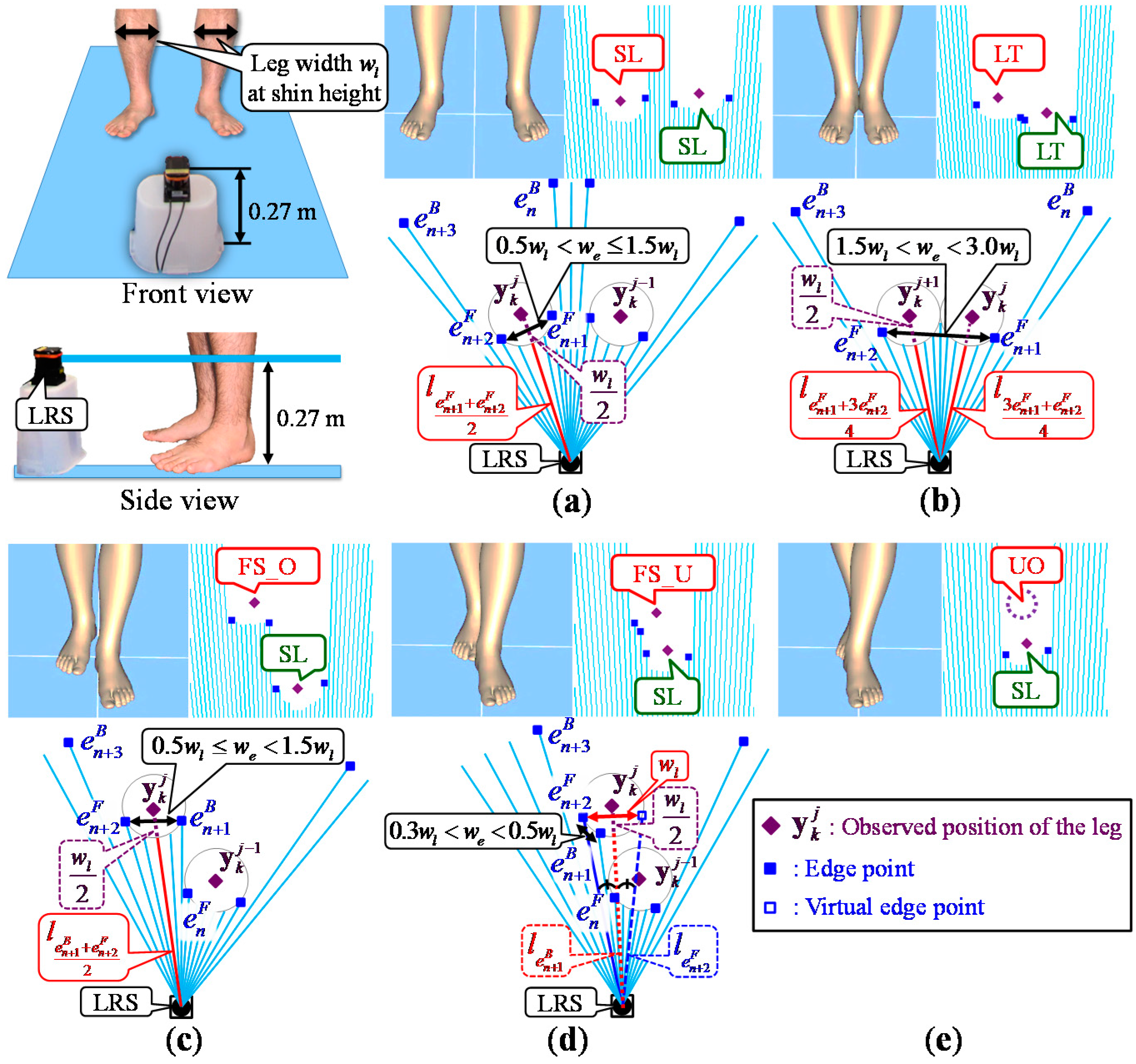
2.3. Leg Detection
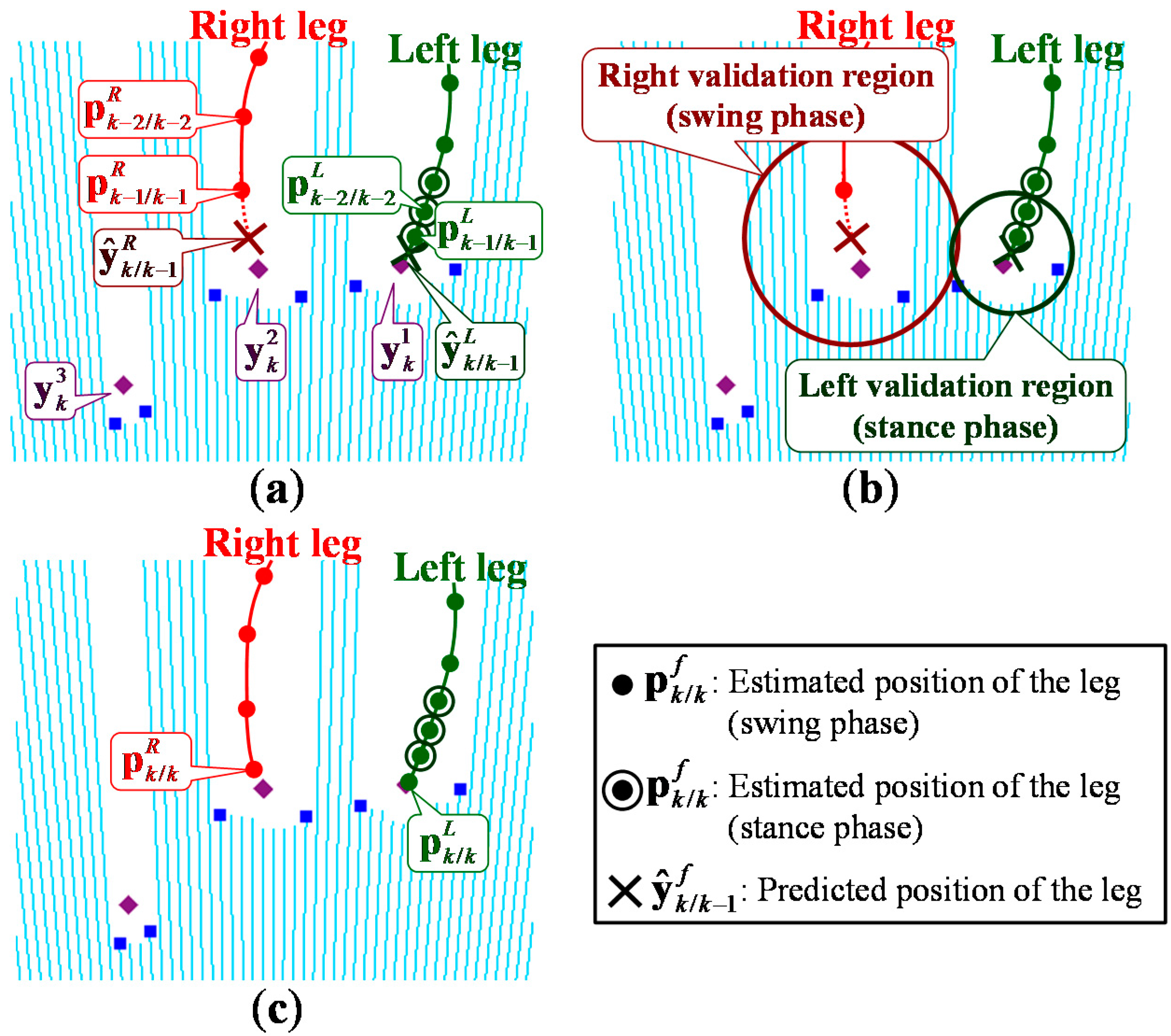
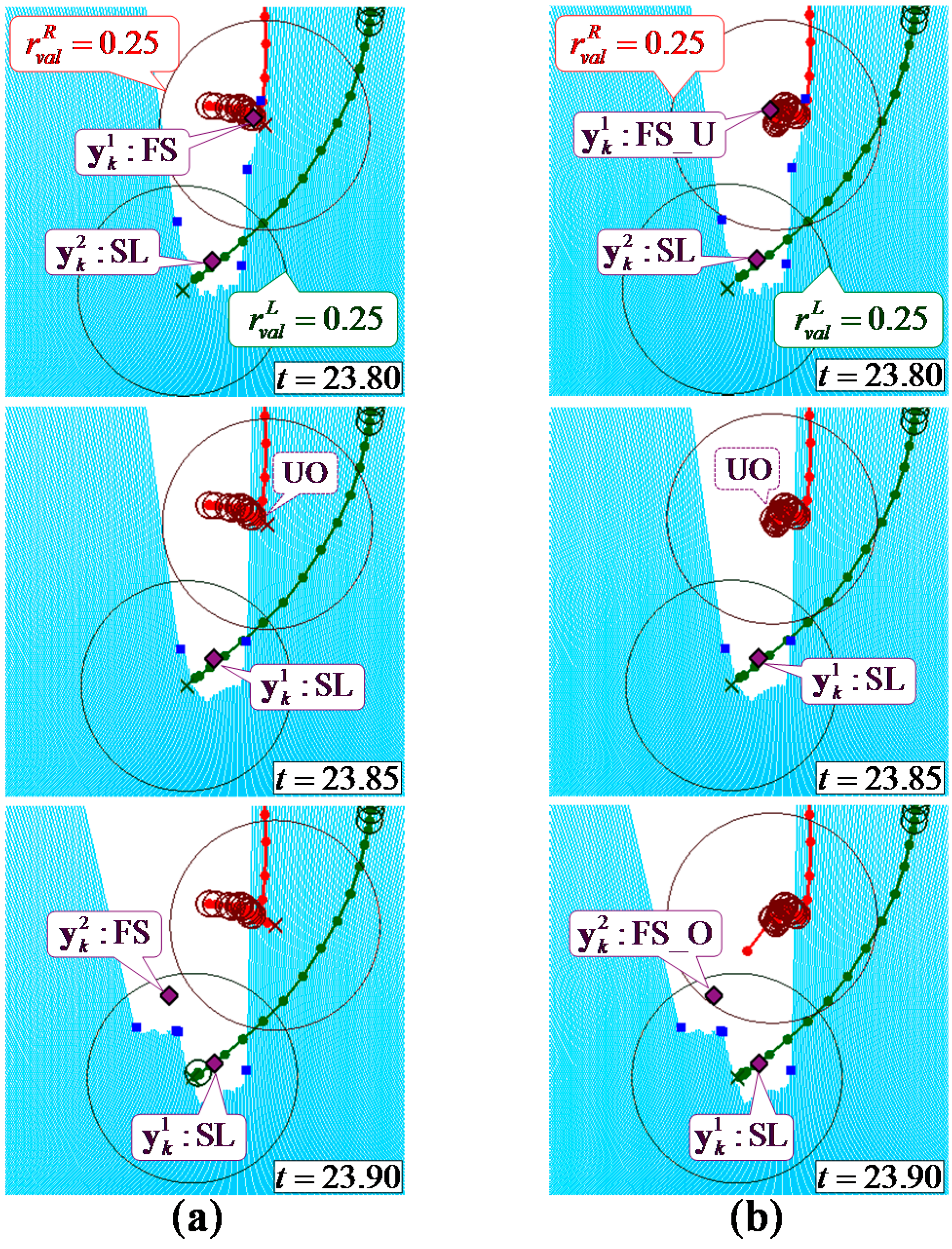
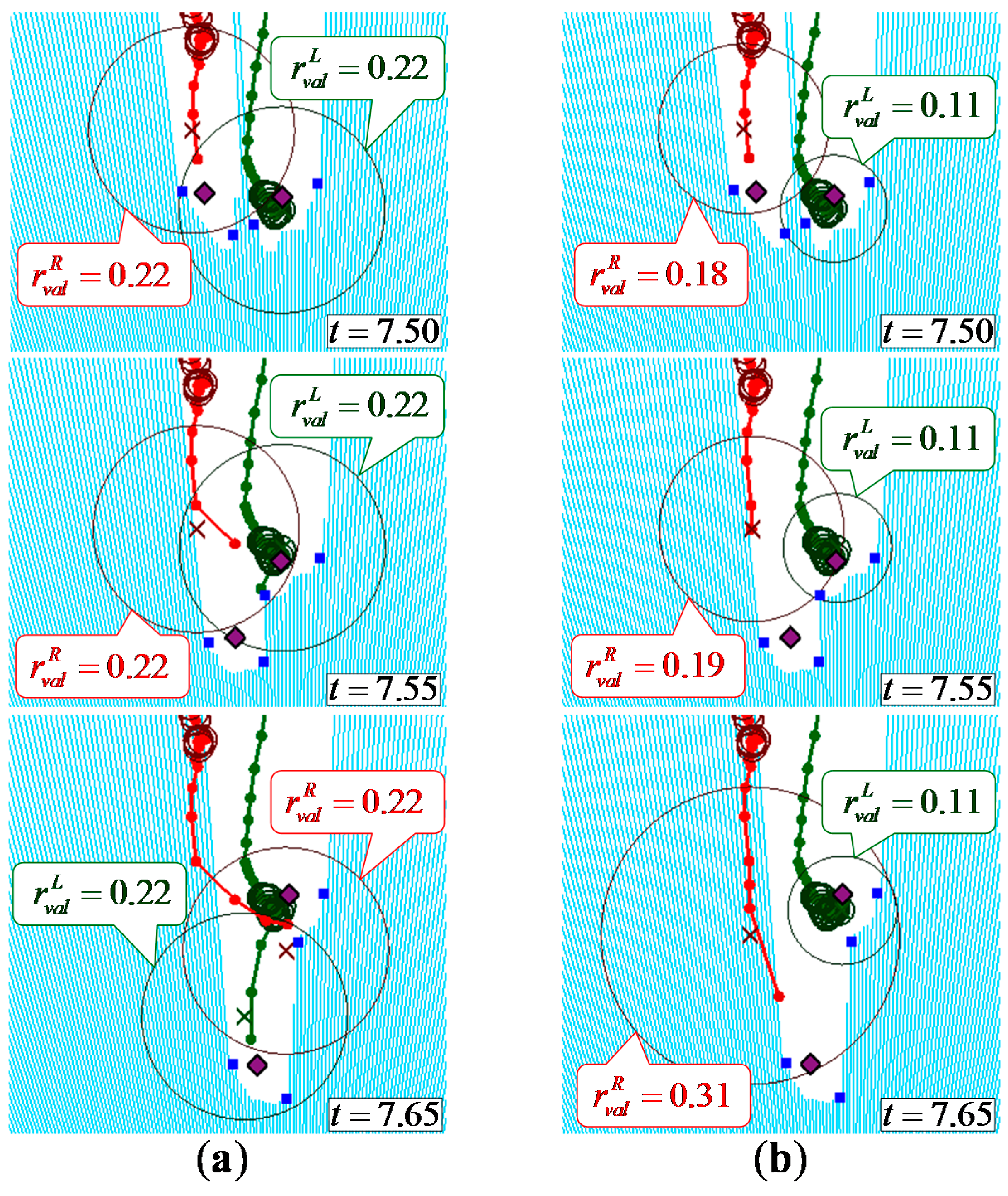
2.4. Leg Tracking
2.4.1. Prediction

2.4.2. Data Association

| Gait phase at k − 1 | Observable | Unobservable |
|---|---|---|
| Stance phase | ||
| Swing phase |
2.4.3. Correction
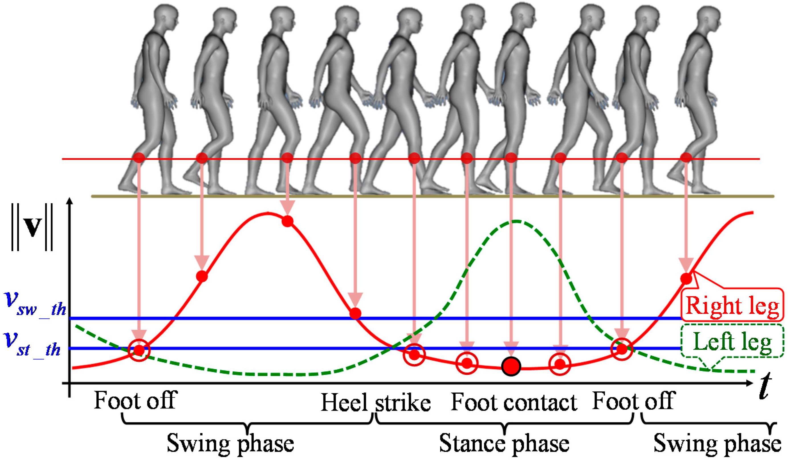
2.4.4. Gait Phase Identification
2.5. Walking Parameters Extraction
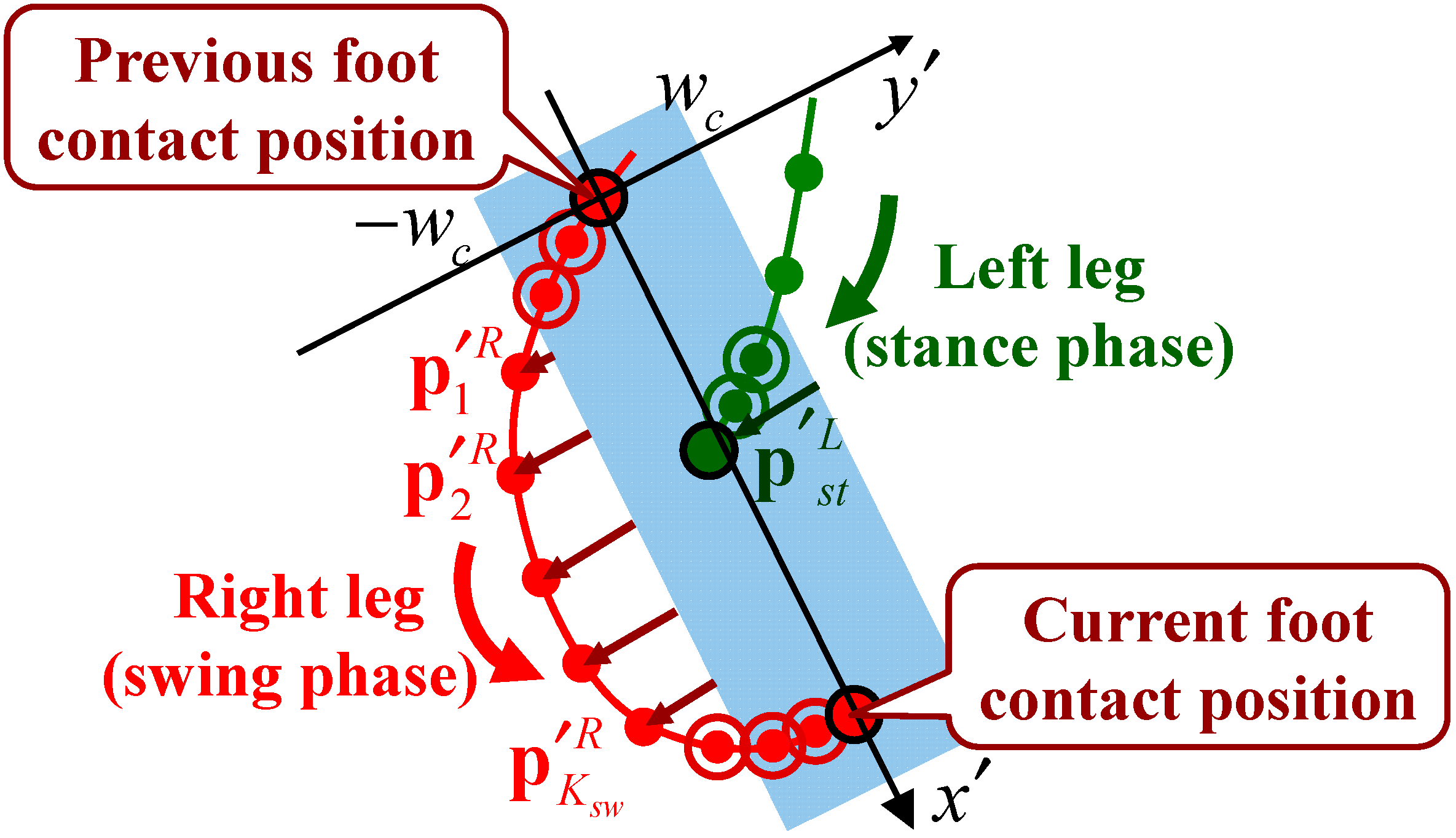
2.5.1. Foot Contact Position Extraction
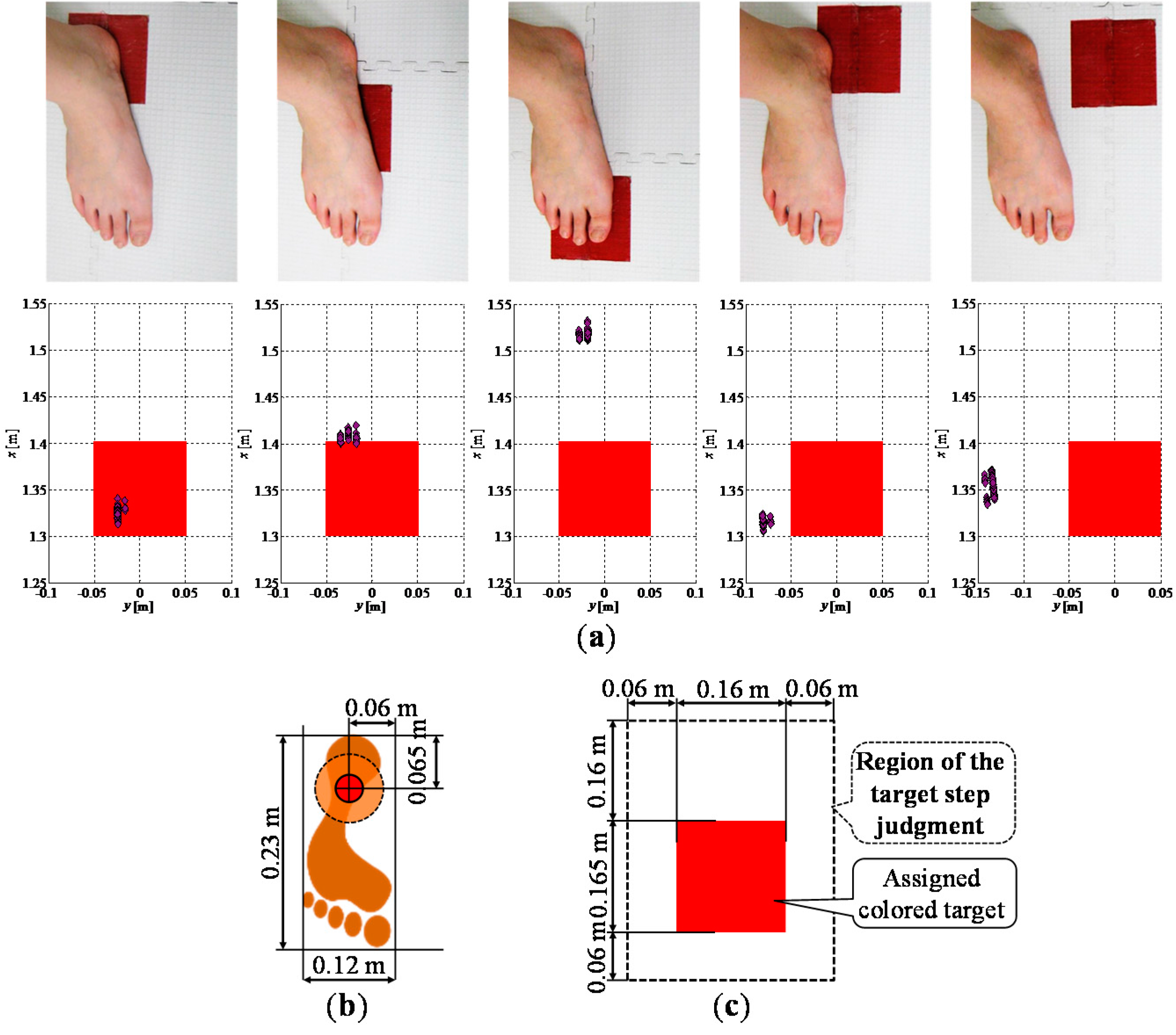
2.5.2. Target Step Judgment

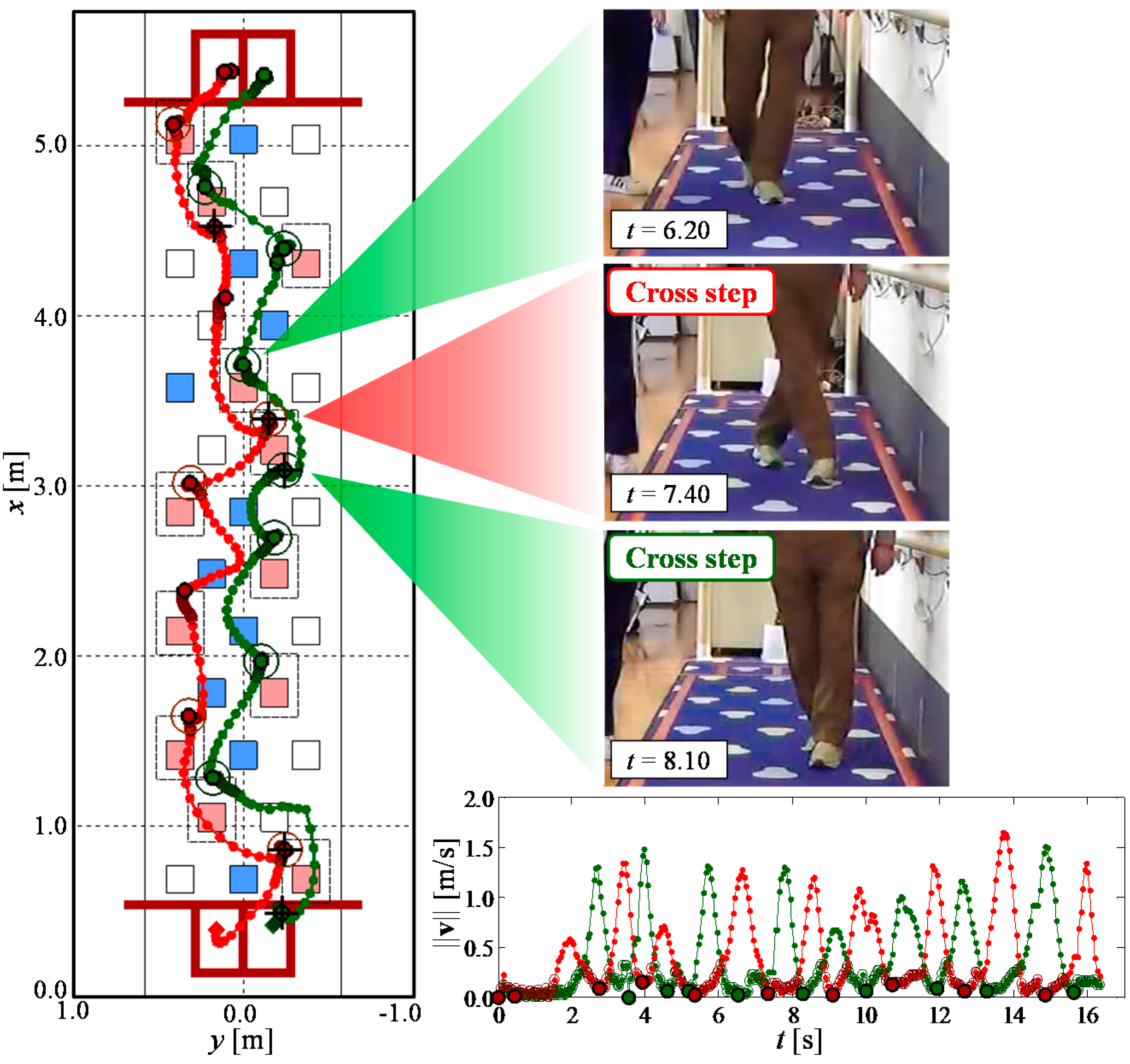
2.5.3. Cross Step Detection

3. Experiments
3.1. Participants and Environment
| Detection Range | 0.1–30 m, max. 60 m |
| 270° | |
| Measurement Accuracy | 0.1–10 m: ±0.03 m |
| 10–30 m: ±0.05 m | |
| Angular Resolution | 0.25°(360°/1440) |
3.2. Verification of Leg Tracking


| Five Observed Leg Patterns | Radius of the Validation Region | Participants not Using a Stick (14 people, 42 Trials) | Participants Using a Stick (2 People, 6 Trials) | Total (16 People, 48 Trials) | |||
|---|---|---|---|---|---|---|---|
| Number of Lost Tracks | Number of False Tracks | Number of Lost Tracks | Number of False Tracks | Success Rate | |||
| Method 1 | No | 6 | 5 | 3 | 0 | 70.8% (34/48) | |
| Method 2 | Yes | 1 | 1 | 0 | 2 | 91.7% (44/48) | |
| Method 3 | Yes | 14 | 0 | 1 | 2 | 64.6% (31/44) | |
| Proposed | Yes | Variable | 0 | 0 | 0 | 2 | 95.8% (46/48) |
3.3. Verification of Walking Parameters Extraction
| Participants not Using a Stick (381 Steps, 16 Cross Steps) | Participants Using a Stick (33 steps, Three Cross Steps) | Total (414 Steps, 19 Cross Steps) | ||||
|---|---|---|---|---|---|---|
| Number of Non-Judgments and Non-Detections | Number of Misjudgments and False Detections | Number of Non-Judgments and Non-Detections | Number of Misjudgments and False Detections | Success Rate of Judgment and Detection | Rate of Misjudgment and False Detection | |
| Target step judgment | 4 | 3 | 0 | 3 | 99.0% (410/414) | 1.4% (6/414) |
| Cross step detection | 2 | 0 | 2 | 0 | 78.9% (15/19) | 0.0% (0/15) |

4. Conclusions
Acknowledgments
Author Contributions
Conflicts of Interest
References
- Deandrea, S.; Bravi, F.; Turati, F.; Lucenteforte, E.; La, V.C.; Negri, E. Risk factors for falls in older people in nursing homes and hospitals. A systematic review and meta-analysis. Arch. Gerontol. Geriatr. 2013, 56, 407–415. [Google Scholar] [CrossRef] [PubMed]
- Deandrea, S.; Lucenteforte, E.; Bravi, F.; Foschi, R.; La, V.C.; Negri, E. Risk factors for falls in community-dwelling older people: A systematic review and meta-analysis. Epidemiology 2010, 21, 658–668. [Google Scholar] [CrossRef] [PubMed]
- Da Costa, B.R.; Rutjes, A.W.; Mendy, A.; Freund-Heritage, R.; Vieira, E.R. Can Falls Risk Prediction Tools Correctly Identify Fall-prone Elderly Rehabilitation Inpatients? A Systematic Review and Meta-Analysis. PLoS ONE 2012, 7. [Google Scholar] [CrossRef] [PubMed]
- Gillespie, L.D.; Robertson, M.C.; Gillespie, W.J.; Sherrington, C.; Gates, S.; Clemson, L.M.; Lamb, S.E. Interventions for preventing falls in older people living in the community. Cochrane Database Syst. Rev. 2012, 9. [Google Scholar] [CrossRef]
- Leveille, S.G.; Jones, R.N.; Kiely, D.K.; Hausdorff, J.M.; Shmerling, R.H.; Guralnik, J.M.; Kiel, D.P.; Lipsitz, L.A.; Bean, J.F. Chronic musculoskeletal pain and the occurrence of falls in an older population. J. Am. Med. Assoc. 2009, 302, 2214–2221. [Google Scholar] [CrossRef]
- World Health Organization. WHO Global Report on Falls Prevention in Older Age; WHO Press: Geneva, Switzerland, 2008. [Google Scholar]
- Hauer, K.; Lamb, S.E.; Jorstad, E.C.; Todd, C.; Becker, C. Systematic review of definitions and methods of measuring falls in randomized controlled fall prevention trials. Age Aging 2006, 35, 1–5. [Google Scholar] [CrossRef]
- Karlsson, M.K.; Magnusson, H.; von Schewelov, T.; Rosengren, B.E. Prevention of falls in the elderly—A review. Osteoporos. Int. 2013, 24, 747–762. [Google Scholar] [CrossRef] [PubMed]
- American Geriatrics Society; British Geriatrics Society; American Academy of Orthopaedic Surgeons Panel on Falls Prevention. Guideline for the prevention of falls in older persons. J. Am. Geriatr. Soc. 2001, 49, 664–672. [Google Scholar]
- Stubbs, B.; Binnekade, T.; Eggermont, L.; Sepehry, A.A.; Patchay, S.; Schofield, P. Pain and the risk for falls in community-dwelling older adults: Systematic review and meta-analysis. Arch. Phys. Med. Rehabil. 2014, 95, 175–187. [Google Scholar] [CrossRef] [PubMed]
- Melzer, I.; Oddsson, L.I. The effect of a cognitive task on voluntary step execution in healthy elderly and young individuals. J. Am. Geriatr. Soc. 2004, 52, 1255–1262. [Google Scholar] [CrossRef] [PubMed]
- Melzer, I.; Shtilman, I.; Rosenblatt, N.; Oddsson, L.I. Reliability of voluntary step execution behavior under single and dual task conditions. J. NeuroEng. Rehabil. 2007, 4. [Google Scholar] [CrossRef]
- Yamada, M.; Aoyama, T.; Arai, H.; Nagai, K.; Tanaka, B.; Uemura, K.; Mori, S.; Ichihashi, N. Dual-task walk is a reliable predictor of falls in robust elderly adults. J. Am. Geriatr. Soc. 2011, 59, 163–164. [Google Scholar] [CrossRef] [PubMed]
- Schoene, D.; Lord, S.R.; Delbaere, K.; Severino, C.; Davies, T.A.; Smith, S.T. A randomized controlled pilot study of home-based step training in older people using videogame technology. PLoS ONE 2013, 8. [Google Scholar] [CrossRef] [PubMed]
- Yamada, M.; Higuchi, T.; Tanaka, B.; Uemura, K.; Nagai, K.; Aoyama, T.; Ichihashi, N. Measurements of Stepping Accuracy in a Multitarget Stepping Task as a Potential Indicator of Fall Risk in Elderly Individuals. J. Gerontol. Ser. A Biol. Sci. Med. Sci. 2011, 66A, 994–1000. [Google Scholar] [CrossRef]
- Yamada, M.; Higuchi, T.; Mori, S.; Uemura, K.; Nagai, K.; Aoyama, T.; Ichihashi, N. Maladaptive turning and gaze behavior induces impaired stepping on multiple footfall targets during gait in older individuals who are at high risk of falling. Arch. Gerontol. Geriatr. 2012, 54, 102–108. [Google Scholar] [CrossRef] [PubMed]
- Kistler Instruments Ltd. Available online: http://www.kistler.com/us/en/index (accessed on 12 February 2014).
- Davis, R.B.; Õunpuu, S.; Tyburski, D.; Gage, J.R. A gait analysis data collection and reduction technique. J. Hum. Mov. Sci. 1991, 10, 575–587. [Google Scholar] [CrossRef]
- Vicon Motion Systems Ltd. Available online: http://vicon.com (accessed on 12 February 2014).
- Nippon Shooter Ltd. Available online: http://www.nippon-shooter.co.jp/prod/lifecare/dayservice/movie03.html (accessed on 12 February 2014). (In Japanese)
- Hokuyo Automatic Co., Ltd. Available online: http://www.hokuyo-aut.jp (accessed on 12 February 2014).
- Microsoft. Kinect for Windows Sensor Components and Specifications, Microsoft Developer Network. Available online: http://msdn.microsoft.com/en-us/library/jj131033.aspx (accessed on 18 April 2015).
- Ozaki, M.; Kakimuma, K.; Hashimoto, M.; Takahashi, K. Laser-Based Pedestrian Tracking in Outdoor Environments by Multiple Mobile Robots. Sensors 2012, 12, 14489–14507. [Google Scholar] [CrossRef]
- Lee, J.H.; Abe, K.; Tsubouchi, T.; Ichinose, R.; Hosoda, Y.; Ohba, K. Collision-Free Navigation Based on People Tracking Algorithm with Biped Walking Model. In Proceedings of the IEEE/RSJ International Conference on Intelligent Robots and Systems, Nice, France, 22–26 September 2008; pp. 2983–2989.
- Schulz, D.; Burgard, W.; Fox, D.; Cremers, A.B. People Tracking with Mobile Robot using Sample-based Joint Probabilistic Data Association Filters. Int. J. Robot. Res. 2003, 22, 99–116. [Google Scholar] [CrossRef]
- Almeida, J.; Almeida, A.; Araujo, R. Tracking Multiple Moving Objects for Mobile Robotics Navigation. In Proceedings of the IEEE International Conference on Emerging Technologies and Factory Automation, Catania, Italy, 19–22 September 2005; pp. 203–210.
- Bellotto, N.; Hu, H. Multisensor-Based Human Detection and Tracking for Mobile Service Robots. IEEE Trans. Syst. Man Cybern. Part B Cybern. 2009, 39, 167–181. [Google Scholar] [CrossRef]
- Sabatini, A.M.; Colla, V. A method for sonar based recognition of walking people. Robot. Auton. Syst. 1998, 25, 117–126. [Google Scholar] [CrossRef]
- Basso, F.; Munaro, M.; Michieletto, S.; Pagello, E.; Menegatti, E. Fast and Robust Multi-people Tracking from RGB-D Data for a Mobile Robot. In Proceedings of the 12th International Conference on Intelligent Autonomous Systems, Jeju Island, Korea, 26–29 June 2012.
- Pallejà, T.; Teixidò, M.; Tresanchez, M.; Palacìn, J. Measuring Gait Using a Ground Laser Range Sensor. Sensors 2009, 9, 9133–9146. [Google Scholar] [CrossRef] [PubMed]
- Teixidò, M.; Pallejà, T.; Tresanchez, M.; Noguès, M.; Palacìn, J. measuring Oscillating Walking Paths with a LIDAR. Sensors 2011, 11, 5071–5086. [Google Scholar] [CrossRef]
- Shotton, J.; Fitzgibbon, A.; Cook, M.; Sharp, T.; Finocchino, M.; Moore, R.; Kipman, A.; Blake, A. Real-time Human Pose Recognition in Parts from Single Depth Images. In Proceedings of the IEEE International Conference on Computer Vision and Pattern Recognition, Colorado Springs, CO, USA, 20–25 June 2011; pp. 1297–1304.
- Ratsamee, P.; Mae, Y.; Ohara, K.; Takubo, T.; Arai, T. People Tracking with Body Pose Estimation for Human Path Prediction. In Proceedings of the IEEE International Conference on Mechatronics and Automation, Chengdu, China, 5–8 August 2012; pp. 1915–1920.
- Auvinet, E.; Multon, F.; Meunier, J. New Lower-Limb Gait Asymmetry Indices Based on a Depth Camera. Sensors 2015, 15, 4605–4623. [Google Scholar] [CrossRef] [PubMed]
- Gritti, A.P.; Tarabini, O.; Guzzi, J.; di Caro, G.A.; Caglioti, V.; Gambardella, L.M.; Giusti, A. Kinect-Based People Detection and Tracking from Small-Footprint Ground Robots. In Proceedings of the IEEE/RSJ International Conference on Intelligent Robots and Systems, Chicago, IL, USA, 14–18 September 2014; pp. 4096–4103.
- Konstantinova, P.; Udvarev, A.; Semerdjiev, T. A Study of a Target Tracking Algorithm Using Global Nearest Neighbor Approach. In Proceedings of the International Conference on Computer Systems and Technologies, Sofia, Bulgaria, 17–18 June 2003.
- Bar-Shalom, Y.; Willett, P.K.; Tian, X. Tracking and Data Fusion: A Handbook of Algorithms; YBS Publishing: Storrs, CT, 2011. [Google Scholar]
- Matsumura, T.; Moriguchi, T.; Yamada, M.; Uemura, K.; Nishiguchi, S.; Aoyama, T.; Takahashi, M. Development of measurement system for task oriented step tracking using laser range finder. J. NeuroEng. Rehabil. 2013, 10. [Google Scholar] [CrossRef]
© 2015 by the authors; licensee MDPI, Basel, Switzerland. This article is an open access article distributed under the terms and conditions of the Creative Commons Attribution license (http://creativecommons.org/licenses/by/4.0/).
Share and Cite
Yorozu, A.; Nishiguchi, S.; Yamada, M.; Aoyama, T.; Moriguchi, T.; Takahashi, M. Gait Measurement System for the Multi-Target Stepping Task Using a Laser Range Sensor. Sensors 2015, 15, 11151-11168. https://doi.org/10.3390/s150511151
Yorozu A, Nishiguchi S, Yamada M, Aoyama T, Moriguchi T, Takahashi M. Gait Measurement System for the Multi-Target Stepping Task Using a Laser Range Sensor. Sensors. 2015; 15(5):11151-11168. https://doi.org/10.3390/s150511151
Chicago/Turabian StyleYorozu, Ayanori, Shu Nishiguchi, Minoru Yamada, Tomoki Aoyama, Toshiki Moriguchi, and Masaki Takahashi. 2015. "Gait Measurement System for the Multi-Target Stepping Task Using a Laser Range Sensor" Sensors 15, no. 5: 11151-11168. https://doi.org/10.3390/s150511151
APA StyleYorozu, A., Nishiguchi, S., Yamada, M., Aoyama, T., Moriguchi, T., & Takahashi, M. (2015). Gait Measurement System for the Multi-Target Stepping Task Using a Laser Range Sensor. Sensors, 15(5), 11151-11168. https://doi.org/10.3390/s150511151