
Robust 3D Position Estimation in Wide and Unconstrained Indoor Environments


Abstract
:1. Introduction
1.1. Contribution
- Providing a detailed overview of the entire system and its capabilities across the use cases.
- Extending and comparing the results from the heterogeneous use cases to embed the presented approach into a larger technological and application context.
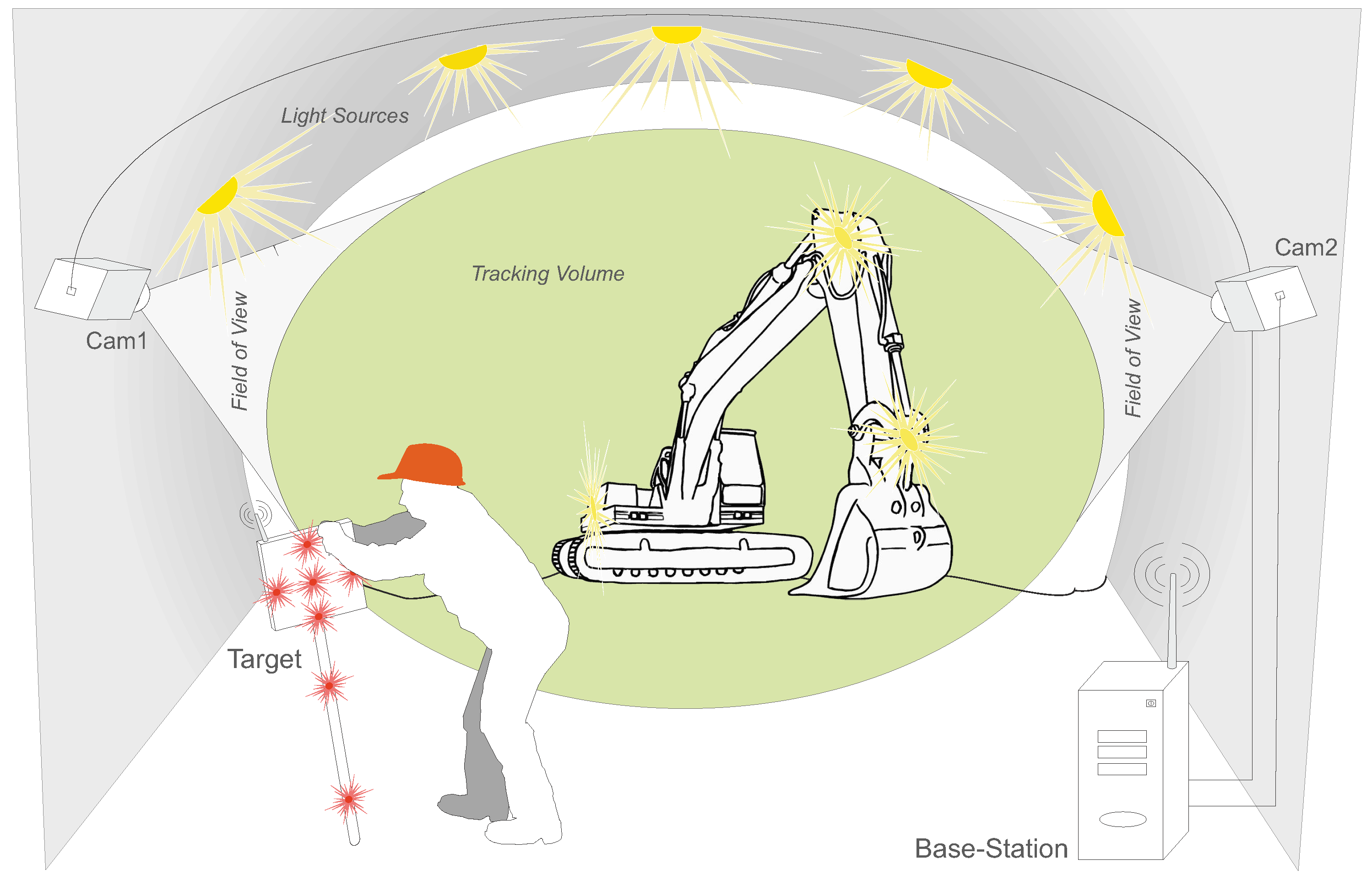
- Wide-Area Tracking in Unconstrained Environments: The system provides model-based infrared optical tracking of multiple rigid-body targets in wide, unconstrained volumes while requiring a minimal hardware setup of two cameras. The system automatically tracks visible target(s), thus temporary occlusions can be recovered and no initial manual sighting is necessary as it is a prerequisite of laser measurement systems. At each stage of the system’s workflow—target training, extrinsic camera calibration and 3D position tracking—no constraining of the tracking volume is necessary. This enables the system to fully function in indoor environments with static and moving light sources, varying ambient up to very poor illumination.
- Robust Camera Calibration: The presented external calibration approach allows for parameter estimation of stereo cameras rigs with wide baselines under varying illumination. Therefore, the tracking target is re-used to artificially generate point features that are crucial in poorly illuminated environments or in scenarios with little geometric structure. Furthermore, the target’s properties support reliable correspondence matching without requiring the epipolar geometry for correspondence analysis.
- Adaptable Design and Ease of Use; Targets are designed to be highly reconfigurable and are equipped with standard infrared light emitting diodes. They can act as a hand-held point measure unit or can be attached to arbitrary objects. The small amount of hardware enables quick system installation, yielding only minimal disturbances of activities within the tracking volume. No further preconditioning of the environment is necessary, increasing the system’s ease of use during setup and maintenance and making it unobtrusive and cost efficient.
- General Purpose Tracking System: The system’s design allow for application to a broad range of scenarios. To demonstrate the system’s capabilities to act a general purpose measurement tool in indoor environments, it was experimentally applied to three different unconstrained wide area scenarios. (1) position tracking for VR/AR tasks; (2) tunneling surveying tasks and (3) autonomous machine guidance for underground construction. The experimental results show relative millimeter point accuracy up to 30 m and centimeter deviation up to 90 m. These results clearly improve state-of-the-art systems and reveal the system’s applicability for a broad range of use cases.

1.2. Related Work
1.2.1. Radio Frequency and Ultra Sound
1.2.2. Optical Tracking
1.2.3. Laser Measurement Systems
2. Methodology
2.1. System Requirements
- Cover Wide Tracking Volume: Target(s) shall be tracked with two cameras up to distances of 100 m. To account for different real-life tracking scenarios, the distance between both cameras (baseline) may vary. Both cameras are connected to one processing unit, thus data exchange interfaces are required that support long distance cable transmission.
- Accurate Camera Calibration: To optimally compensate optical aberrations, the intrinsic and extrinsic calibration must be able to be performed with the complete camera encasement. The extrinsic calibration has to be capable to be performed during on-going activities in the tracking volume and thus must be able to cope with heavy interferences and large distances.
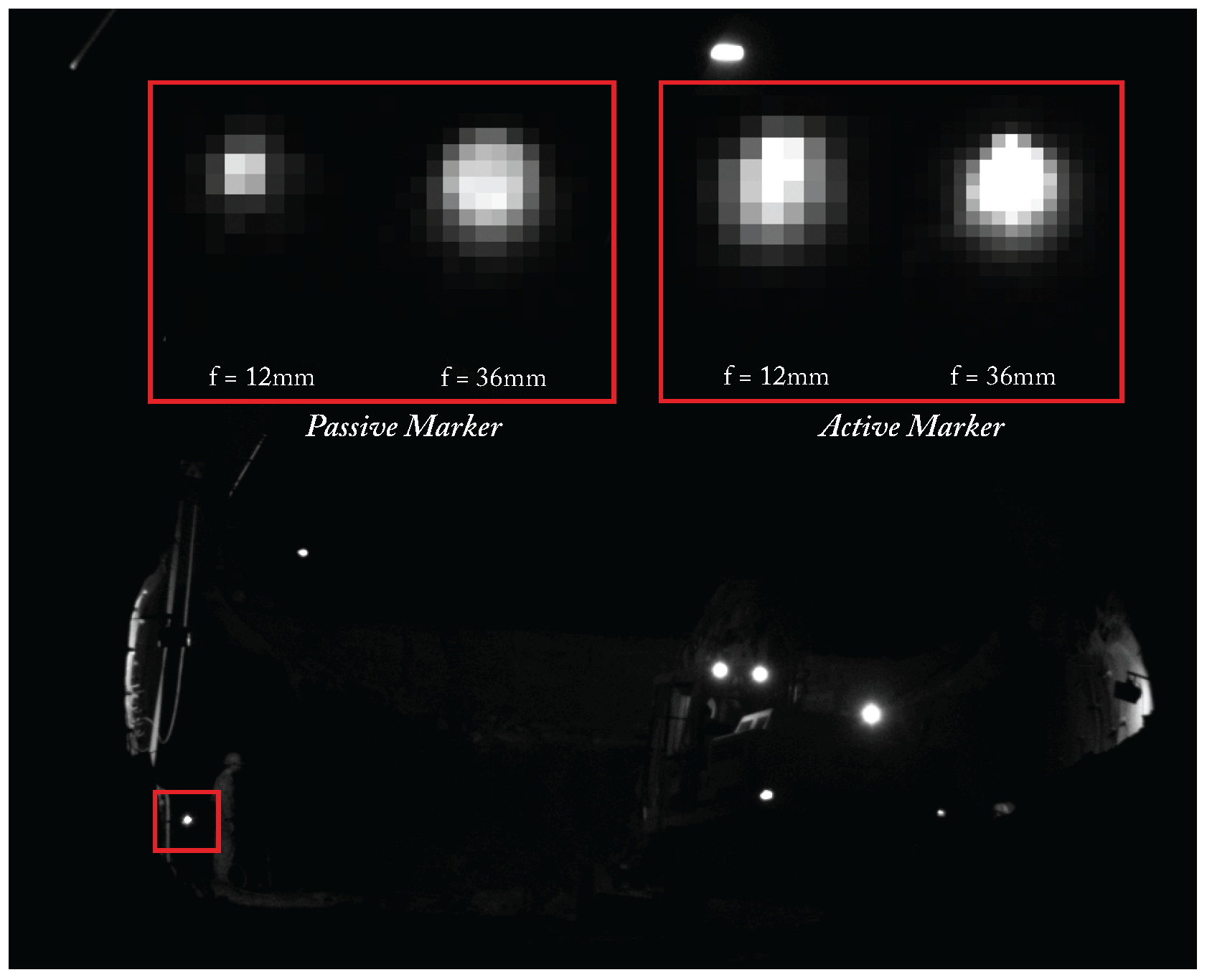
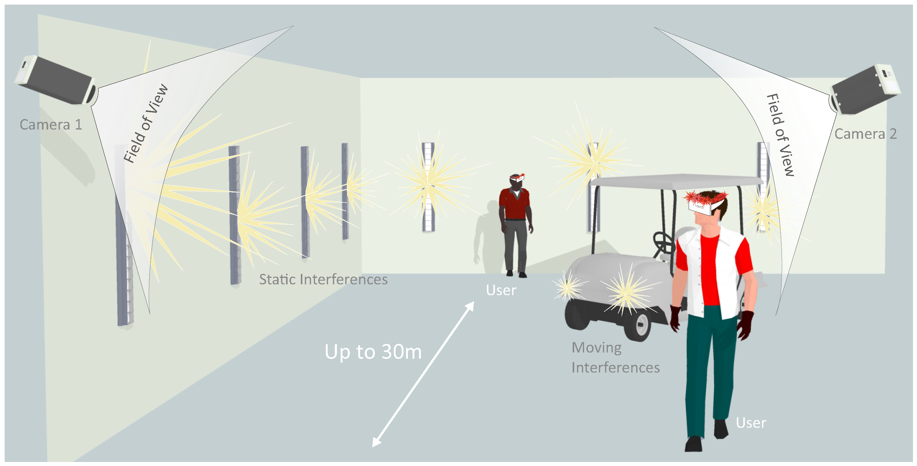
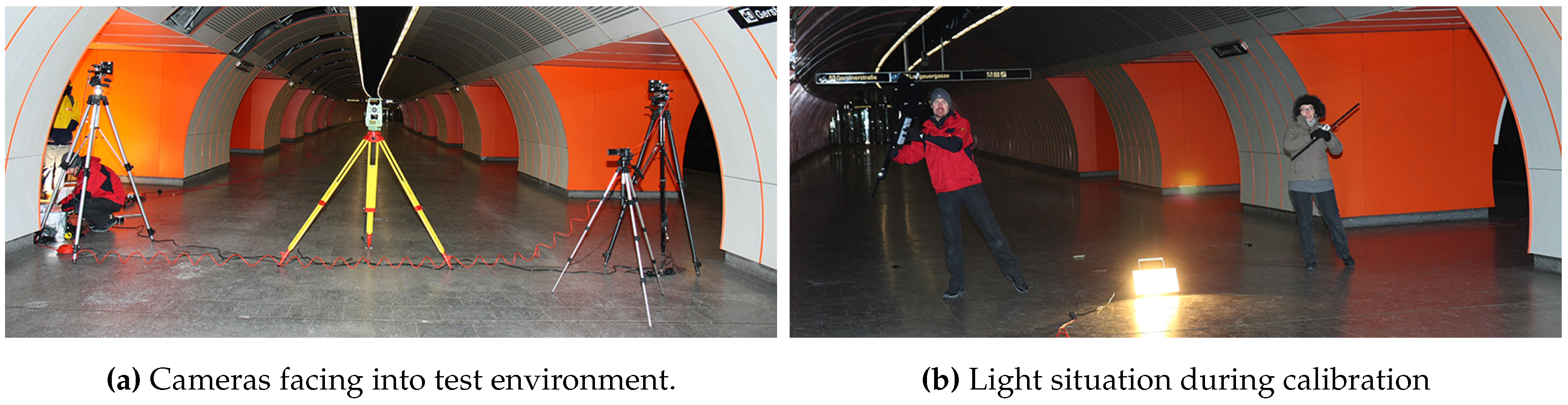
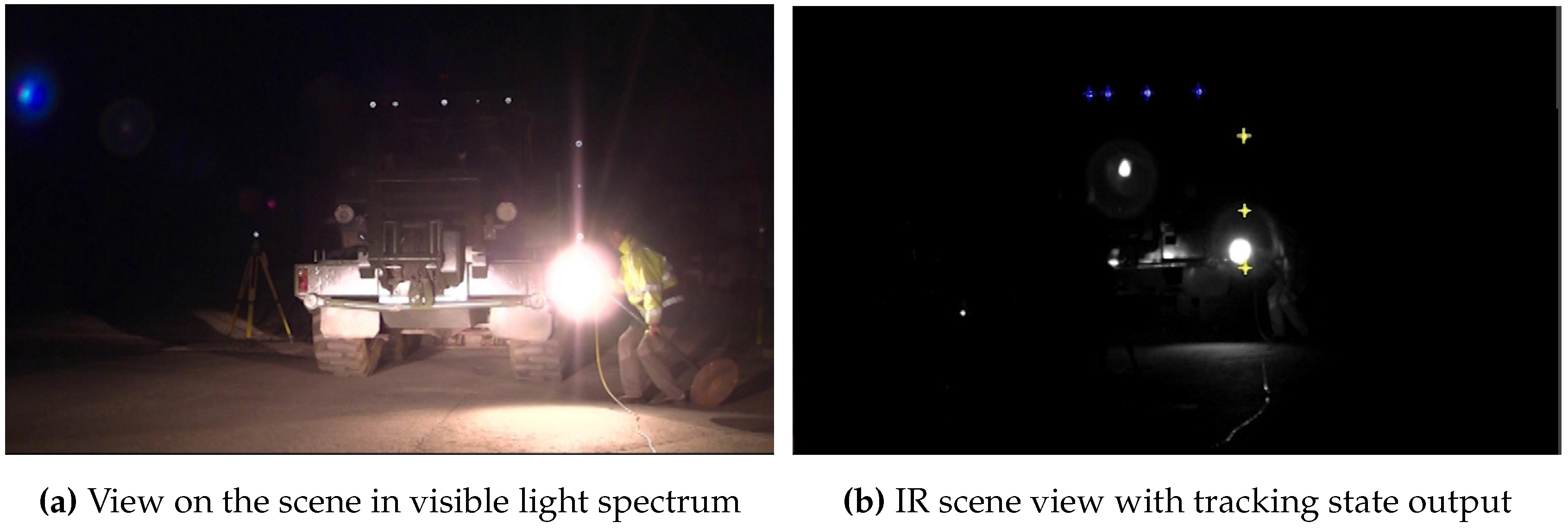
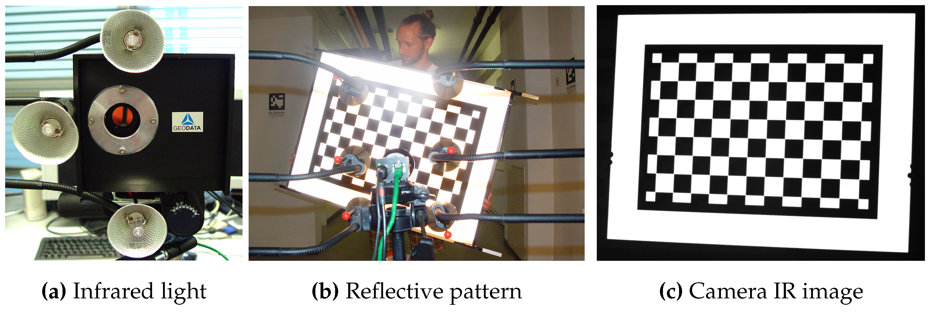
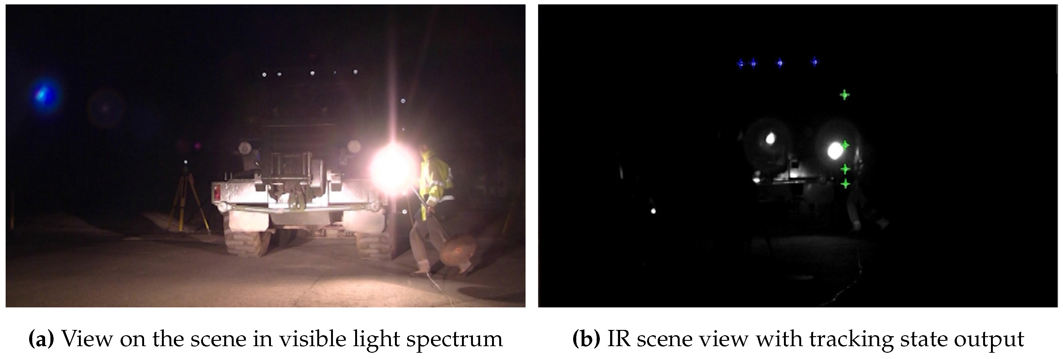
- Unique Target Identification: Interfering light sources must be filtered to allow for a robust target detection during calibration and tracking, as illustrated in Figure 1b.
- Continuous and Accurate 3D Position: The hardware and software algorithms have to ensure precise target detection at large distances and in environments with poor visibility due to particles (dust, dirt) in the air. Continuous 3D position estimation must be provided within the whole tracking volume.
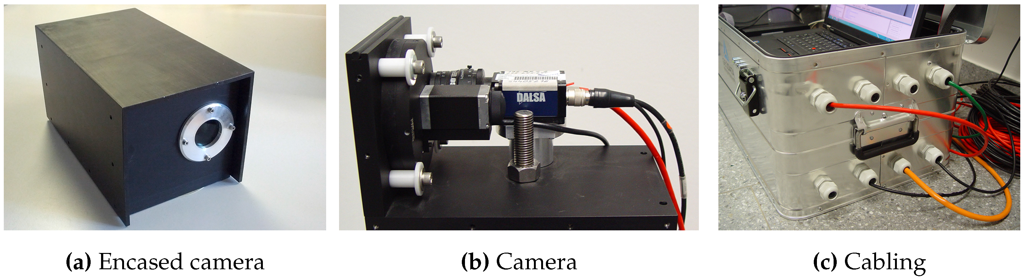
- Robust Hardware Casing: To ensure system reliability in real-life environments, hardware components (cameras, lenses, target, processing unit) have to be encased to be dust- and dampness proof. Nevertheless, the system must be easy and quick to setup and the target should be usable even with thick gloves. Furthermore, side effects on the camera’s field-of-view (FOV) as well as optical aberrations must be considered when encasing the vision parts of the system.
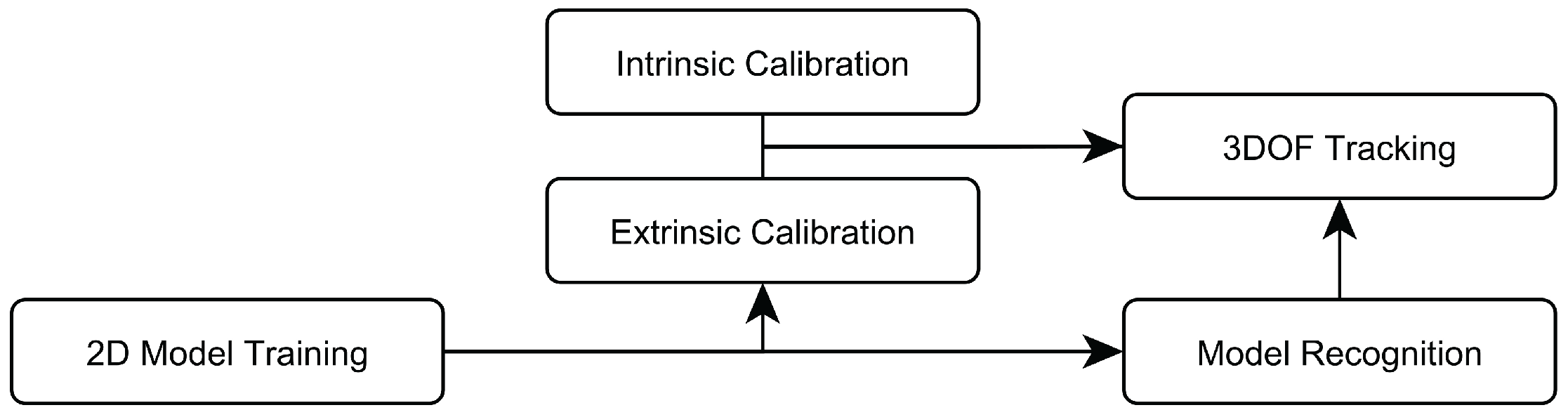
2.2. Algorithmic Overview

2.3. Target Design
- The line target can robustly detected across both camera images with no a priori knowledge of the camera’s epipolar geometry. Thereby, extrinsic camera calibration can be performed even in the presence of interfering lights by using the visual features of the target. Competing approaches [21,22,23] perform Model Fitting in 3D space, making these systems not able to cope with unconstrained conditions during camera calibration.
- We can re-purpose the tracking target as calibration apparatus since Model Fitting is always performed in the 2D image domain. Thereby, the overall amount of necessary hardware for setup and maintenance can be reduced.
- Fixing the IR-LEDs in a 2D manner increases the physical robustness of the target against accidental breaking off when touching the target during usage; this is especially an issue for tracking at larger distances since the target requires enlarged dimensions as well. Accidental breaking off is a common problem with the rather sensitive 3D rigid targets that need frequent replacement or repair by experts.
2.4. Camera Calibration
2.4.1. Background
2.4.2. Intrinsic Calibration

2.4.3. Extrinsic Calibration
2.5. Interference Filtering
2.5.1. Model Training
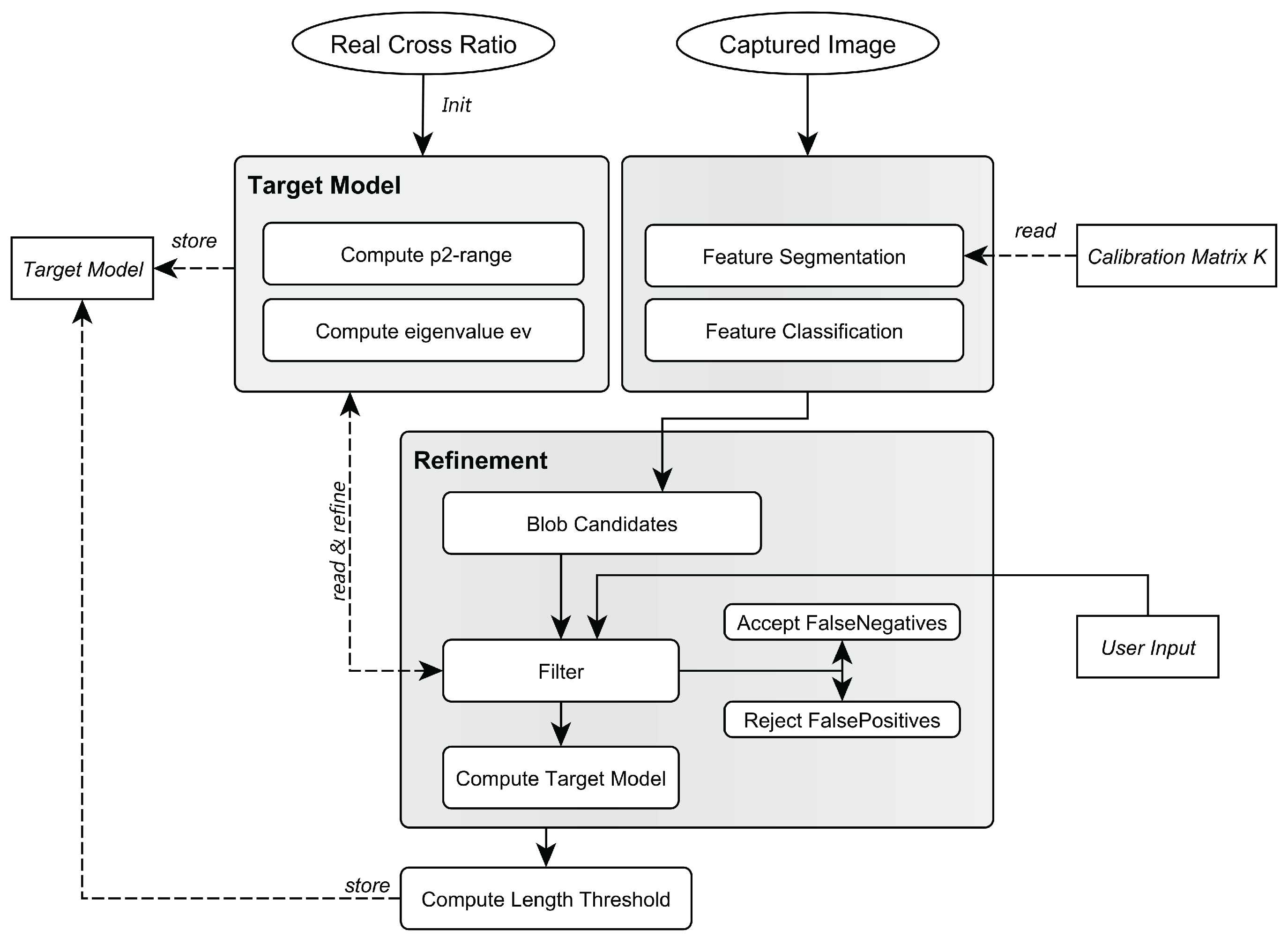
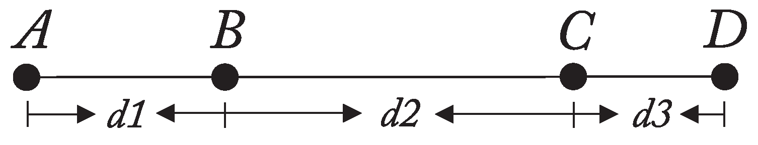
- The distances (see Figure 4) between the target’s LEDs are precisely measured using a total station.
- Based on , the cross ratio λ is computed and used as input argument for the function J to obtain an initial estimate for . The eigenvalue of the moment matrix M as a measure for collinearity is set to an initial value such as .
- The target is captured at all intended tracking distances to obtain a sufficient number of samples (images) for the complete tracking volume.
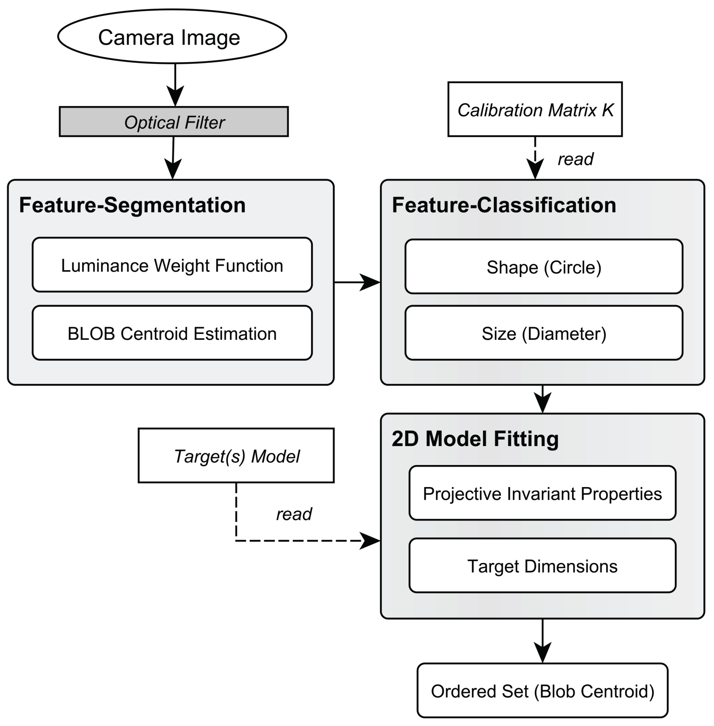
- Each of the captured images is then processed and blob candidates are obtained by performing feature segmentation and classification (see Figure 9). and are applied to the blob candidates and subsequently refined to account for noise of cross ratio and collinearity.
- After the refinement phase, the minimum and maximum length of the target in the 2D images over all images are measured to obtain a threshold .
- Finally, the obtained model is stored, containing as the minimum and maximum values of the pattern’s -invariants, , as the collinearity error model and .
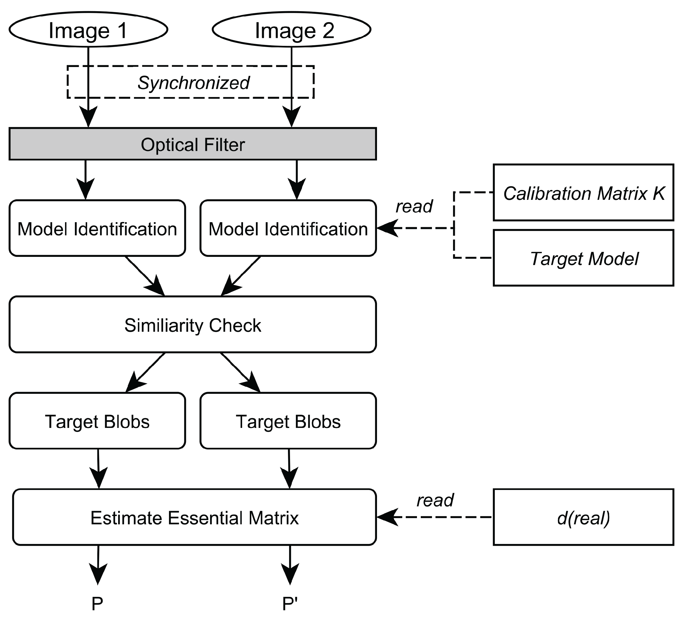
2.5.2. Model Identification

2.6. 3 Degree-Of-Freedom Tracking
2.7. Occlusion Recovery
3. System Development
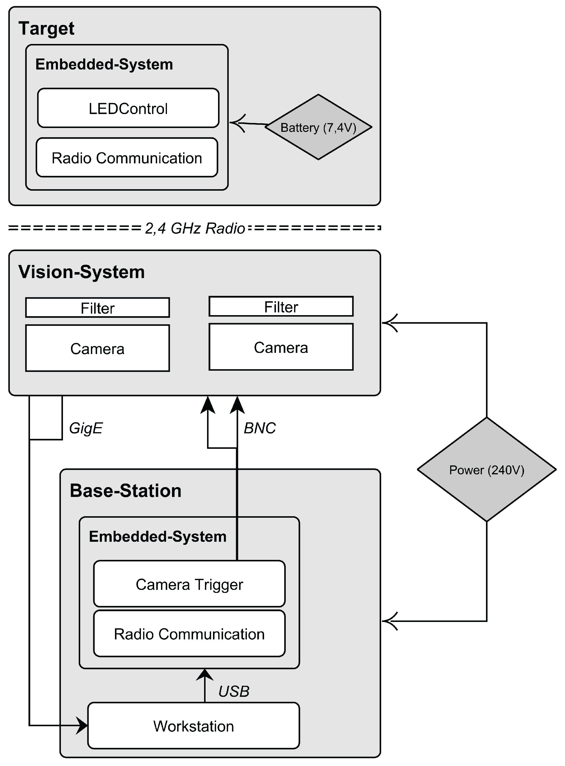
3.1. Hardware

3.1.1. Vision System
3.1.2. Workstation
3.1.3. Target
- Target for Virtual Reality: For the VR/AR setup, we developed a target prototype that offers continuously adjustable positioning of the IR-LEDs by fixing each LED separately with nuts on a rigid bar to allow a rapid arrangement of the IR-LEDs. The target prototype has a total length of 687 mm and is equipped with four IR-LEDs OSRAM 4850 E7800 in a permutation invariant constellation. Each IR-LED emits a peak wavelength of 850 nm with a radiant intensity of 40 mW/sr (mW/sr: milli watts per steradian) and features a viewing half angle of . Thereby, robust feature segmentation up to a distance of 30 m can be performed. With the employed vision hardware setup, a minimum distance of 130 mm between two neighboring LEDs is advisable with a shutter speed of 1000 μs to avoid blob overlaps in the camera image at the maximum tracking distance of 30 m. Tracking in a smaller volume automatically leads to a decreased target size with the above mentioned setup. To further reduce the physical target size for volumes up to 30 m, LEDs with different radiant intensity properties are applicable.For testing, the IR-LED bar was attached to the front of a head mounted display. It has to be noted that a single line target is sufficient to determine the user’s (head) 3D position in scenarios in which the user faces the cameras, i.e., in our test setup or in a semi-immersive VR scenario in which the user is tracked in front of a projector wall. In a fully immersive VR environment—where the user freely moves in space—a single line target in combination with two cameras results in occlusions as soon as the user turns around. This occlusion problem can be compensated by applying a composed setup of multiple unique line targets.
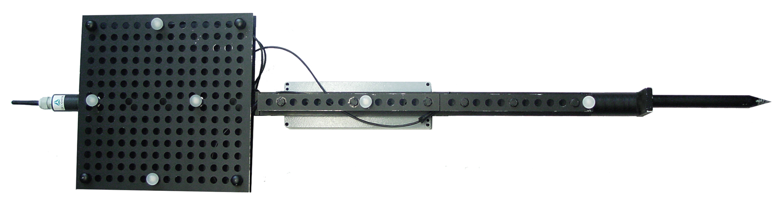
- Target for Tunneling: The target prototype was developed in cooperation with Geodata Ziviltechniker GmbH (Leoben, Austria) and is depicted in Figure 12. The target provides an array of holes at fixed distances, in which the IR-LEDs can be mounted. This allows for the rapid arrangement of multiple IR-LEDs in a permutation invariant geometric constellation. Furthermore, multiple unique constellations can be easily designed to simultaneously track one or more targets in the same tracking volume. The maximal distance between the two outermost IR-LEDs is cm, while the targets total length is cm. The target is equipped with six IR-LEDs OSRAM 4850 E7800 to be able to construct a planar pattern in future as well. However, all experimental results are based on four collinear LEDs. Each IR-LED emits at a peak wavelength of 850 nm with a radiant intensity of 40 mW/sr and features a viewing half angle of . A minimum distance of 175 mm between two neighboring LEDs with a shutter speed of 1000 μs is required to ensure robust feature segmentation up to a distance of 70 m. This distance was empirically determined with the given vision.Figure 12. Developed target prototype.
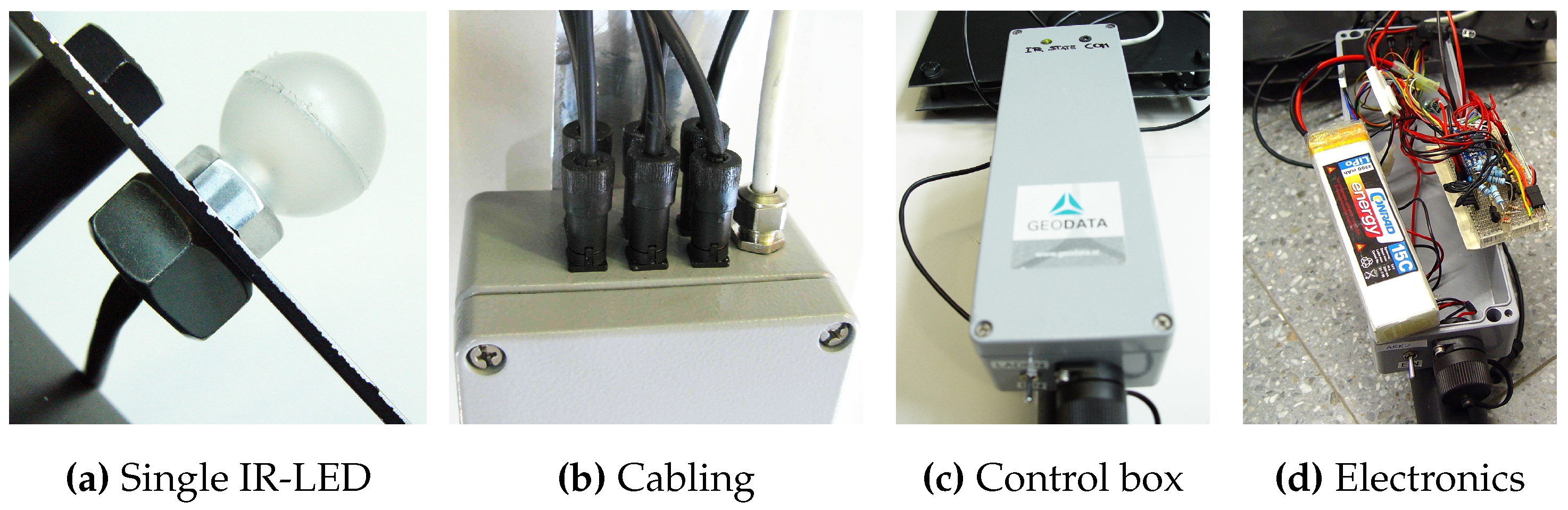
![Sensors 15 29862 g012]() With the developed prototype, the 3D position of a static point can be measured. This is a common tunneling task. Since the target features a 20 cm long tip without any optical markers attached, also points that are not visible to the cameras can be tracked. Thereby, the disadvantage of vision-based tracking systems that require a line-of-sight between cameras and measured point can be compensated to a certain extent. As soon the target is freely moved in space the 3D position of the target’s tip is continuously tracked. In Figure 13, further details of the prototype are shown, including the coating of the IR-LED as well as dampness-proof cabling.Figure 13. Details of the developed target prototype.
With the developed prototype, the 3D position of a static point can be measured. This is a common tunneling task. Since the target features a 20 cm long tip without any optical markers attached, also points that are not visible to the cameras can be tracked. Thereby, the disadvantage of vision-based tracking systems that require a line-of-sight between cameras and measured point can be compensated to a certain extent. As soon the target is freely moved in space the 3D position of the target’s tip is continuously tracked. In Figure 13, further details of the prototype are shown, including the coating of the IR-LED as well as dampness-proof cabling.Figure 13. Details of the developed target prototype.![Sensors 15 29862 g013]()
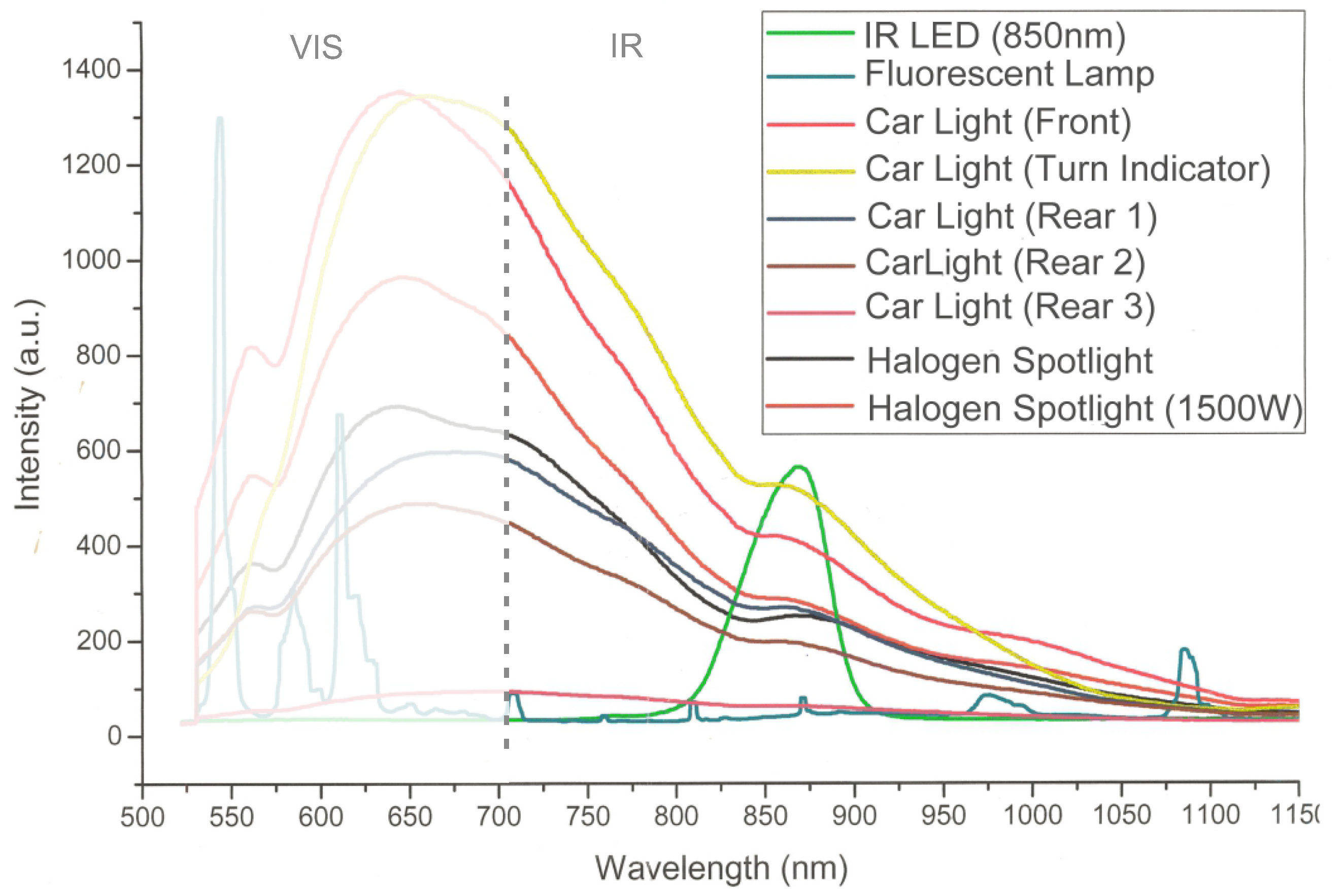
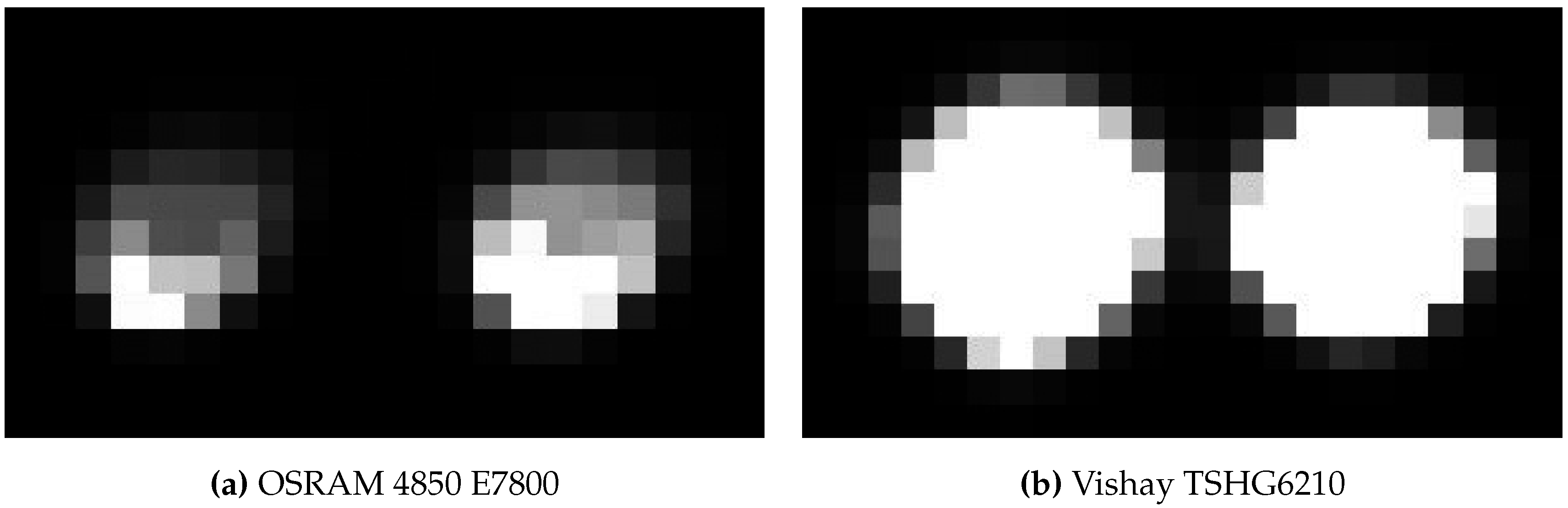
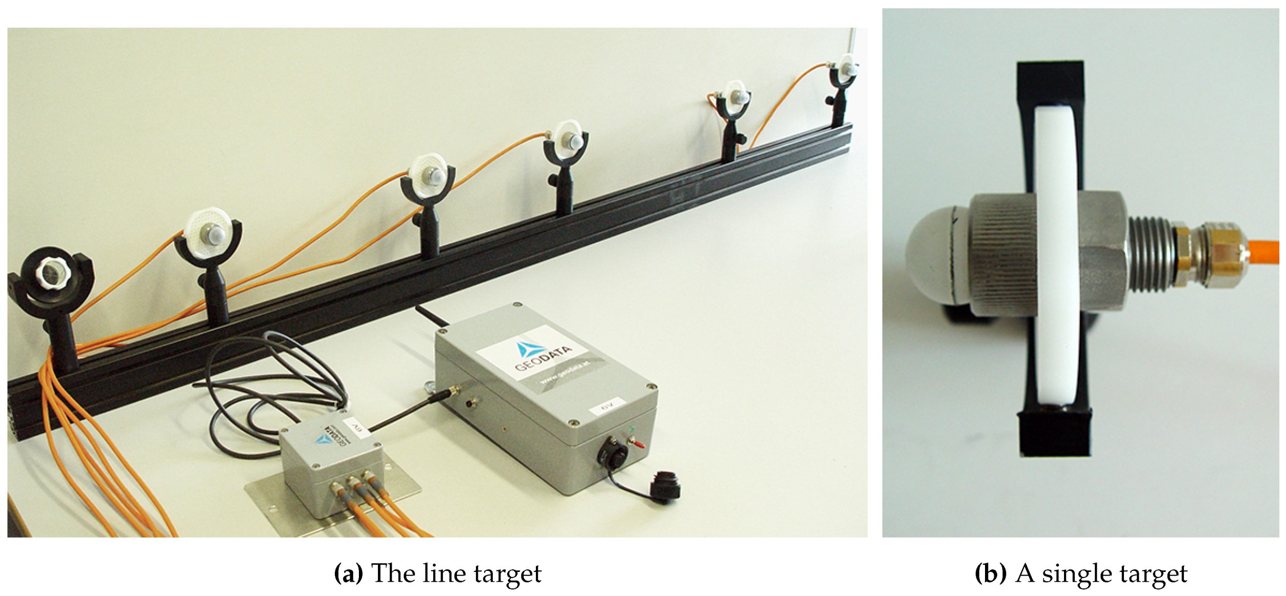
- Target for Machine Guidance: For the third evaluation scenario—machine guidance—two re-configurable targets were developed. In this scenario, a tracking range up to 100 m had to be provided. Therefore, IR-LED tests were performed to account fo the required extended tracking range. To enable reliable tracking throughout the extended tracking range, robust feature segmentation and blob centroid determination must be ensured. Therefore, different LED types from various suppliers have been evaluated at distances from 30–110 m featuring radiant intensities from 40–230 mW/sr. The aim was to find the IR-LED with the best balance between appropriate intensity for long distance feature segmentation and minimal distance between two neighboring LEDs. For all tests, the vision setup from Section 3.1.1 was employed. We ran the LEDs with V, mA and an operating voltage of 5 V. Images were captured with 8 bit, a shutter speed of 1000 μs, unlimited focus and open aperture . Over all tests, the IR-LED Vishay TSHG6210 with 230 mW/sr and a half angle of achieved the best blob quality at large distances.In Figure 14, the blobs of Vishay TSHG6210 and OSRAM 4850 E7800 (used for the target prototypes for VR/AR user tracking and tunneling) are illustrated. The difference in luminance quality and even distribution is clearly visible. For the machine tracking prototype, a target has been constructed in cooperation with Geodata Ziviltechniker GmbH (Leoben, Austria) that consist of multiple Vishay TSHG6210 IR-LEDs. Each LED is encased in a plastic hemisphere which acts as a light diffuser (see Figure 15b) and is installed in the center of a retro-reflecting tape target.Figure 14. Comparison of blob quality at 110 m with an inter LED distance of 34 cm.
![Sensors 15 29862 g014]() The diffuser serves for an optimal light diffusion and feature segmentation as well as protects the IR-LED. The target design enables simultaneous geodetic measurement and optical tracking; thereby, the camera system’s world coordinate system can be transformed into a geodetic reference system for comparison as well as real-life use. Coordinate system transformation is subject to future work, thus this part is not covered and discussed within the proposed work. Four to five of the single IR-LEDs are combined to form a line target, as shown in Figure 15. Each single target is mounted to a cm square bar steel and its position can be freely adjusted along the bar. The minimal LED distance is 22 cm to be able to distinguish between two neighboring LEDs at a distance of 120 m. A geodesic prism can be attached as well, as shown in Figure 15a to measure the target with a theodolite as well. We developed two of these line targets to test multiple constellations as well as simultaneous tracking. All IR-LEDs of both targets are centrally powered by one main unit, featuring battery as well as 240 Hz power supply.Figure 15. The IR-LED line target prototype for machine tracking.
The diffuser serves for an optimal light diffusion and feature segmentation as well as protects the IR-LED. The target design enables simultaneous geodetic measurement and optical tracking; thereby, the camera system’s world coordinate system can be transformed into a geodetic reference system for comparison as well as real-life use. Coordinate system transformation is subject to future work, thus this part is not covered and discussed within the proposed work. Four to five of the single IR-LEDs are combined to form a line target, as shown in Figure 15. Each single target is mounted to a cm square bar steel and its position can be freely adjusted along the bar. The minimal LED distance is 22 cm to be able to distinguish between two neighboring LEDs at a distance of 120 m. A geodesic prism can be attached as well, as shown in Figure 15a to measure the target with a theodolite as well. We developed two of these line targets to test multiple constellations as well as simultaneous tracking. All IR-LEDs of both targets are centrally powered by one main unit, featuring battery as well as 240 Hz power supply.Figure 15. The IR-LED line target prototype for machine tracking.![Sensors 15 29862 g015]()


3.1.4. System Costs
3.2. Software
4. Experimental Results
- User tracking for VR/AR applications
- Handheld target tracking for tunneling
- Machine guidance for mining
4.1. Test Cases and Performance Measures
4.1.1. Calibration Performance
4.1.2. Tracking Performance
- Relative Position Accuracy: To obtain a valid ground truth for evaluating the relative position accuracy of the estimated 3D target position, the geometric distance between the two outermost target’s IR-LEDs is firstly measured to millimeter precision using the Leica TPS700. Thereby, ground truth is determined. During tracking, the position of target’s IR-LEDs are calculated for each frame i and used for obtaining , where ∥ denotes the Euclidean norm. To avoid distortion of the 3D position reconstruction, no predictive filtering is applied for testing. The estimated bar length is then applied to obtain the arithmetic mean with standard deviation over all processed frames , its absolute arithmetic mean deviation and root mean square are denoted as follows:is subsequently employed to obtain the deviation , as an accuracy measure of the distance between the two outermost LEDs, and , as a measure of the relative accuracy of a single LED. Both measures are obtained as follows:Thereby, the relative 3D position accuracy of a single target point can be evaluated against a ground truth throughout the tracking volume.
- Position Stability: Based on the estimated target’s IR-LED , the target’s epicenter is determined during tracking, as described in Section 2.6. To evaluate static jitter of the system and thus the stability (inner accuracy) of the 3D point estimation, the standard deviation of as well as C over the sequence of consecutive frames is calculated and used to evaluate the system’s intrinsic tracking performance.
- Tracking Latency: To obtain a measure for time-dependent tracking performance, the systems latency is measured as the time delay between the change in tracker pose and the time, the system has estimated and outputs the new tracker pose.
4.2. Tracking for Virtual and Augmented Reality
4.2.1. Test Environment
4.2.2. Model Training
4.2.3. Camera Calibration
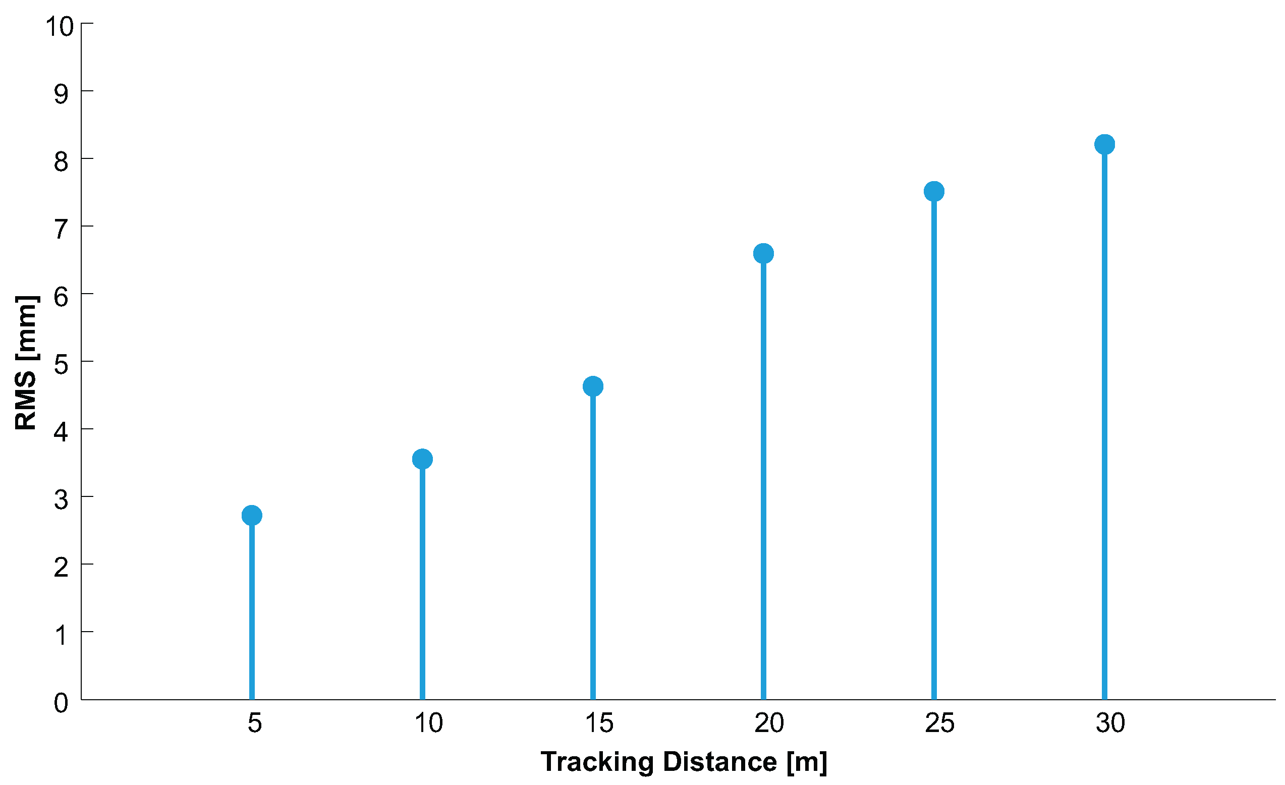
4.2.4. 3D Position Accuracy

| (m) | Calibration 1 | Calibration 2 | Calibration 3 |
|---|---|---|---|
| (mm) | (mm) | (mm) | |
| 5 | 3.39 | 2.99 | 1.78 |
| 10 | 4.12 | 3.91 | 2.63 |
| 15 | 4.76 | 4.54 | 4.58 |
| 20 | 6.08 | 6.23 | 7.47 |
| 25 | 6.64 | 6.97 | 8.92 |
| 30 | 7.44 | 7.96 | 9.22 |
4.2.5. 3D Position Stability
4.2.6. Tracking Performance
4.3. Hand-held Target Tracking for Tunneling

4.3.1. System Encasement
4.3.2. Test Environment
4.3.3. Model Training
4.3.4. Camera Calibration
4.3.5. Accuracy and Stability of 3D Position Estimation
- Relative Position Accuracy: To evaluate the accuracy of the relative 3D position estimation, we performed measurements at three different distances between camera and target, denoted as for each baseline. At each run, the 3D coordinate of each target’s IR-LED as well as of the target’s epicenter were estimated based on 300 consecutive frames.with respect to both baselines and all tracking distances is depicted in Figure 28. As it can be seen for both baselines, increases as increases. This is due to a more inaccurate feature segmentation at larger distances since blob size and luminance diminish. This causes bigger rasterization artifacts than in close range that reduces the accuracy of blob centroid computation. Furthermore, the distances between the blobs in the camera images decrease, especially when large rotations of are applied. With , more accurate results at larger distances can be achieved compared to . 3D point reconstruction [67,68] can be more robustly performed as the baseline increases since the glancing intersection between both rays decreases. All results of and are listed in detail in Table 2.
Table 2. Deviations and error of . (m) m m (mm) (mm) (mm) (mm) 30 0.95 5.29 0.94 1.54 50 13.58 14.24 9.56 3.46 70 21.98 11.04 18.06 10.09 Figure 28. for all and .![Sensors 15 29862 g028]() Up to 30 m with –12 m, the system is able to provide relative 3D accuracy with sub-millimeter deviation of mm for , and mm for . At 70 m, the system achieves 3D accuracy with a maximal deviation of mm for , and mm for . Hence, accuracy decreases as distance increases, and larger baselines results in better accuracy, especially at large distances. However, our evaluation for also reveals 3D position outliers in the result set for 30 m and 50 m since as a consequence, is larger. This does not indicate an overall lack of 3D position robustness since is low at 30 m with and at all distances with . Since no filtering was applied to avoid distortion of the 3D position estimation results, such outliers and its influence can be minimized application tracking using predictive filtering.Overall, our proposed system provides a relative 3D measurement accuracy with an absolute maximal error mm ( mm) for baselines –12 m throughout the entire volume. This accuracy has been achieved under constant movement and changes in rotation of up to .
Up to 30 m with –12 m, the system is able to provide relative 3D accuracy with sub-millimeter deviation of mm for , and mm for . At 70 m, the system achieves 3D accuracy with a maximal deviation of mm for , and mm for . Hence, accuracy decreases as distance increases, and larger baselines results in better accuracy, especially at large distances. However, our evaluation for also reveals 3D position outliers in the result set for 30 m and 50 m since as a consequence, is larger. This does not indicate an overall lack of 3D position robustness since is low at 30 m with and at all distances with . Since no filtering was applied to avoid distortion of the 3D position estimation results, such outliers and its influence can be minimized application tracking using predictive filtering.Overall, our proposed system provides a relative 3D measurement accuracy with an absolute maximal error mm ( mm) for baselines –12 m throughout the entire volume. This accuracy has been achieved under constant movement and changes in rotation of up to . - Stability: After evaluating the accuracy of the relative position estimation, we evaluated the stability of the relative position estimation over 300 consecutive frames. Again, we continuously rotated the target by –. The results are shown in detail in Table 3 with respect to and .
Table 3. Standard deviations at different tracking distances . (m) m m (mm) (mm) (mm) (mm) (mm) (mm) 30 4.07 3.61 12.80 4.92 4.04 5.57 50 4.62 4,49 24.32 6.09 3.09 11.94 70 4.18 6.98 44.92 7.50 5.29 29.61 The deviation of C correlates with the results and findings of Section 4.3.5. Above all, increases most as increases while remain rather constant and are mm for the entire tracking volume. Thus, tracking of the head’s 3D position is very stable for the -axes with both baselines , . Our optical setup as well as the software processing results in millimeter deviation for with both baselines up to 70 m. These results can be improved by using image sensors with higher resolution. varies most at 70 m with with a maximal deviation of mm. With larger baselines, the 3D position estimation of gets more stable ( is decreasing for m).

4.3.6. Tracking Performance
4.4. Machine Tracking for Underground Guidance
4.4.1. Shortcoming of Existing Technology
- They are highly specialized and designed for particular types of machines only; therefore, they lack the universal application to other machine types.
- They can only measure and thus control one machine at a time and lack the capability of tracking multiple machines as well as machine parts that simultaneously operate.
- They can only be used for the purpose of machine guidance but not also for other measuring and surveying tasks such as setting out, profile control or deformation monitoring.
- They lack real-time tracking capability, especially when using totalstations.
- They are expensive, in particular their sensor hardware.
4.4.2. Test Environment

4.4.3. Model Training
4.4.4. Camera Calibration
4.4.5. Accuracy and Stability of 3D Position Estimation
| (m) | (mm) | (mm) | (mm) | (mm) |
|---|---|---|---|---|
| 20 | 7.28 | 0.19 | 0.12 | 0.73 |
| 30 | 17.19 | 0.18 | 0.09 | 0.59 |
| 40 | 29.04 | 1.57 | 1.28 | 5.86 |
| 50 | 42.62 | 0.94 | 0.27 | 3.51 |
| 60 | 49.04 | 0.56 | 0.23 | 3.16 |
| 70 | 49.60 | 0.65 | 0.37 | 4.33 |
| 80 | 60.72 | 1.05 | 0.59 | 4.71 |
| 90 | 78.88 | 0.90 | 0.50 | 5.91 |
| 100 | 89.31 | 3.70 | 1.28 | 23.53 |
| (m) | (mm) | (mm) | (mm) |
|---|---|---|---|
| 20 | 0.03 | 0.03 | 0.15 |
| 30 | 0.13 | 0.10 | 1.74 |
| 40 | 0.14 | 0.08 | 2.22 |
| 50 | 0.32 | 0.17 | 4.57 |
| 60 | 0.39 | 0.14 | 4.08 |
| 70 | 0.72 | 0.15 | 5.90 |
| 80 | 2.79 | 0.41 | 7.47 |
| 90 | 2.97 | 0.54 | 10.72 |
| 100 | 2.71 | 0.43 | 18.21 |
| 110 | 6.31 | 0.85 | 26.77 |
| 120 | 4.24 | 0.82 | 31.60 |
Influence of Vibrations
| (m) | Test 1 | Test 2 | ||||||
|---|---|---|---|---|---|---|---|---|
| (mm) | (mm) | (mm) | (mm) | (mm) | (mm) | (mm) | (mm) | |
| 20 | 7.36 | 0.10 | 0.09 | 0.33 | 7.37 | 0.68 | 0.42 | 2.30 |
| 40 | 32.63 | 0.17 | 0.16 | 0.68 | 32.51 | 0.54 | 0.39 | 3.40 |
| 60 | 53.40 | 0.81 | 0.41 | 3.52 | 53.23 | 1.07 | 0.47 | 4.61 |
4.4.6. Tracking Performance for Machine Guidance
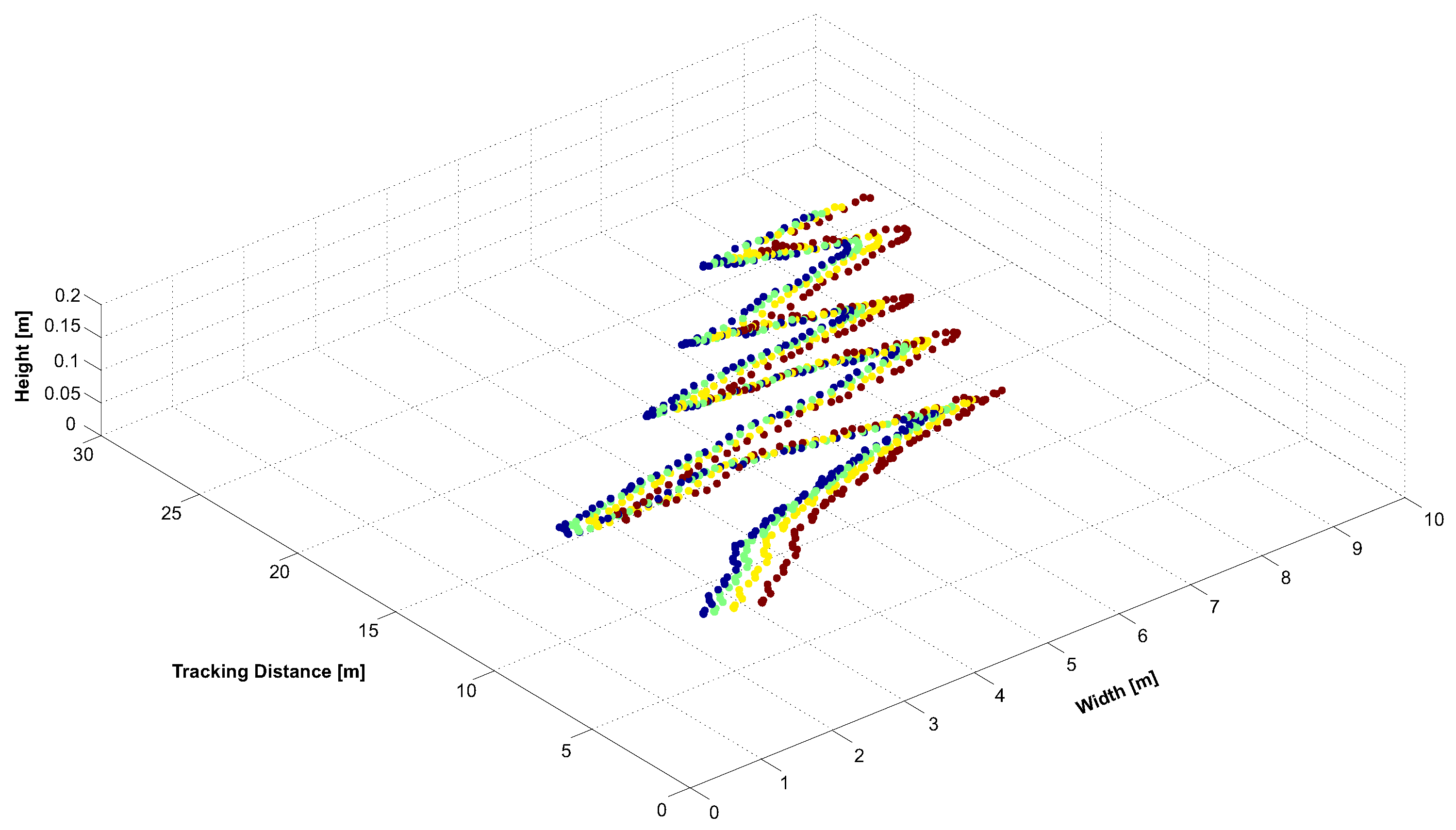
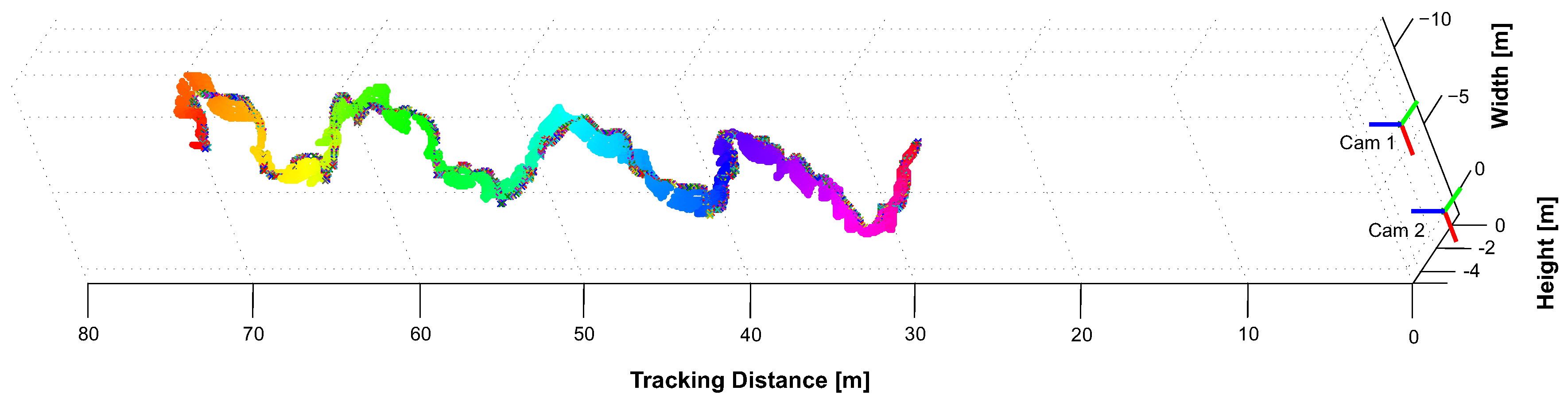
- Tracking under Normal Visibility: First, we tracked the wheel loader under normal visibility conditions during driving operation from 20–110 m. The estimated 3D points of the target are depicted in Figure 31 where only the horizontal target is shown for better visualization. The wheel loader was tracked over a sequence of 2560 frames; in only two frames of this data set tracking was not successful. All tracking results are directly plotted, as no filtering to remove outliers is applied. Thereby, the robustness and accuracy of the entire tracking pipeline could be objectivity evaluated, resulting in a robust and continuous tracking.Figure 31. Kinematic tracking of the horizontal target from 20–110 m with m.
![Sensors 15 29862 g031]()
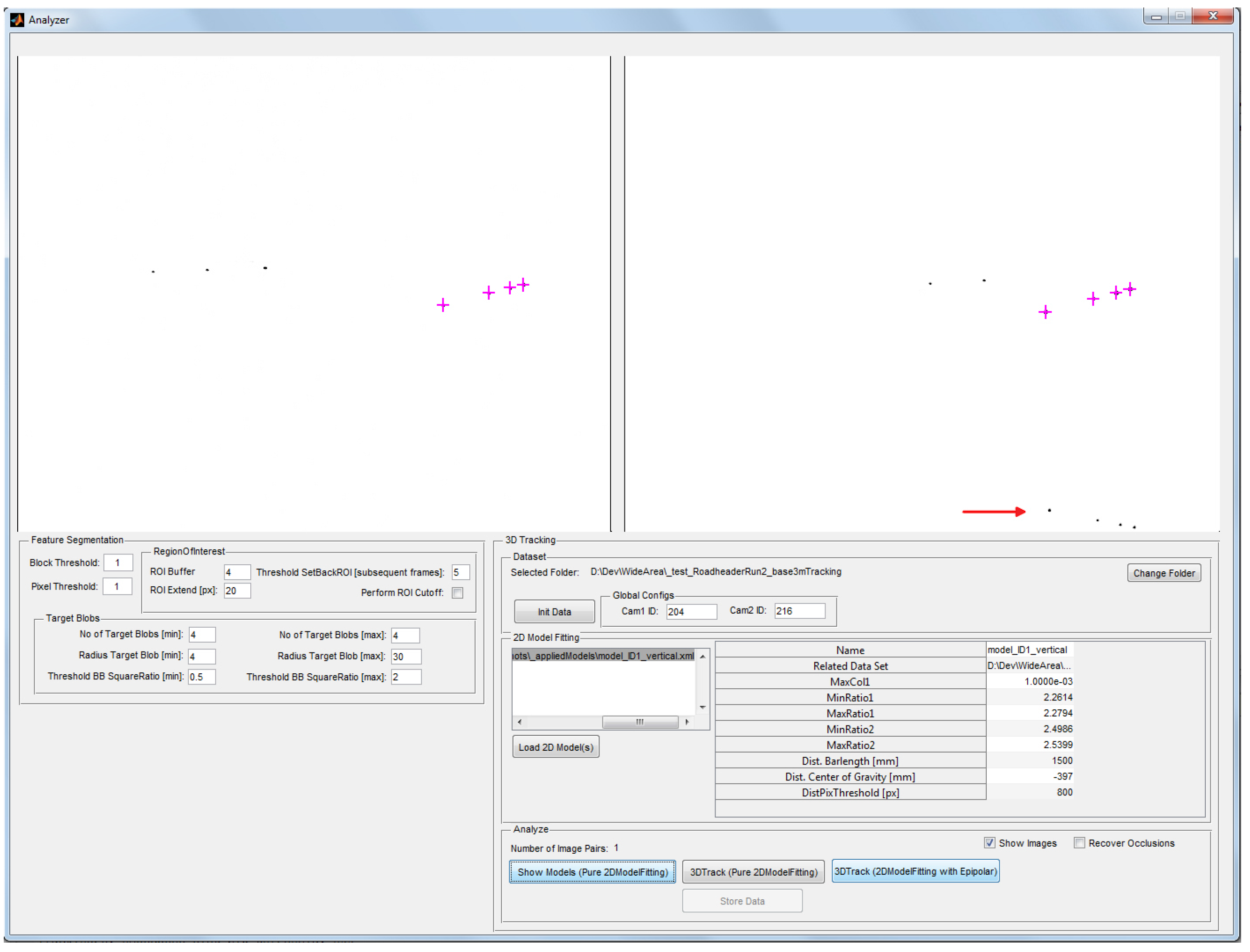
- Tracking with Occlusions and Poor Visibility: Next, disturbing infrared light sources were held in the line of sight and fog has been produced artificially by a machine to simulate difficult environmental conditions and other disturbing influences. In the following, three example images are given to test both environmental interferences. In each example, both targets are simultaneously tracked and the data output of the tracking pipeline indicates a successful target tracking of the horizontal target with blue crosses, and green for the vertical target. In case of occlusions, a successful target model identification is marked by yellow crosses.To test the system’s robustness to filter interfering lights, both targets were tracked over a sequence of 499 subsequent frames while the wheel loader was positioned at a distance m in front of the cameras with m. The horizontal target could be tracked in each frame of the sequence as it was not heavily affected by the interfering lights. The vertical model was subject to heavy occlusions and interferences. It’s model could be fully identified in more than of the frames. In 206 frames, occlusions of one or more IR-LEDs occurred. In case of one occluded LED, the target model could still be identified and its 3D epicenter was estimated after occlusion recovery was performed. In the accuracy and stability data, we found comparable results to the measurements obtained during accuracy and stability evaluation in Section 4.4.5 (see Table 4) with mm and mm. This demonstrates the robustness of model identification and recovery of the tracking pipeline.As it can be seen in Figure 32 and Figure 33, the manually inserted disturbing lights only affect the model identification in case that the interfering lights are directly in front of or very close to the target’s IR-LEDs. This case is given in Figure 32 where the heavy interference leads to the occlusion of one LED of the vertical target. However, the tracking pipeline is still able to correctly identify the target model, as indicated by the yellow crosses in Figure 32b. Thereby, the system is able to subsequently recover the missing LED in 3D for epicenter estimation. The heavy light interference that is illustrated in Figure 33 did not lead to occlusions of the target due to the LED’s properties. Both targets’ models are fully identified and tracked by the tracking pipeline despite the interference.Figure 32. The vertical target is successfully identified (yellow crosses) despite occlusions.
![Sensors 15 29862 g032]() Figure 33. Both targets’ models are identified and tracked despite heavy interfering light.
Figure 33. Both targets’ models are identified and tracked despite heavy interfering light.![Sensors 15 29862 g033]() Figure 34. Both targets’ models are fully identified and tracked during fog tests.
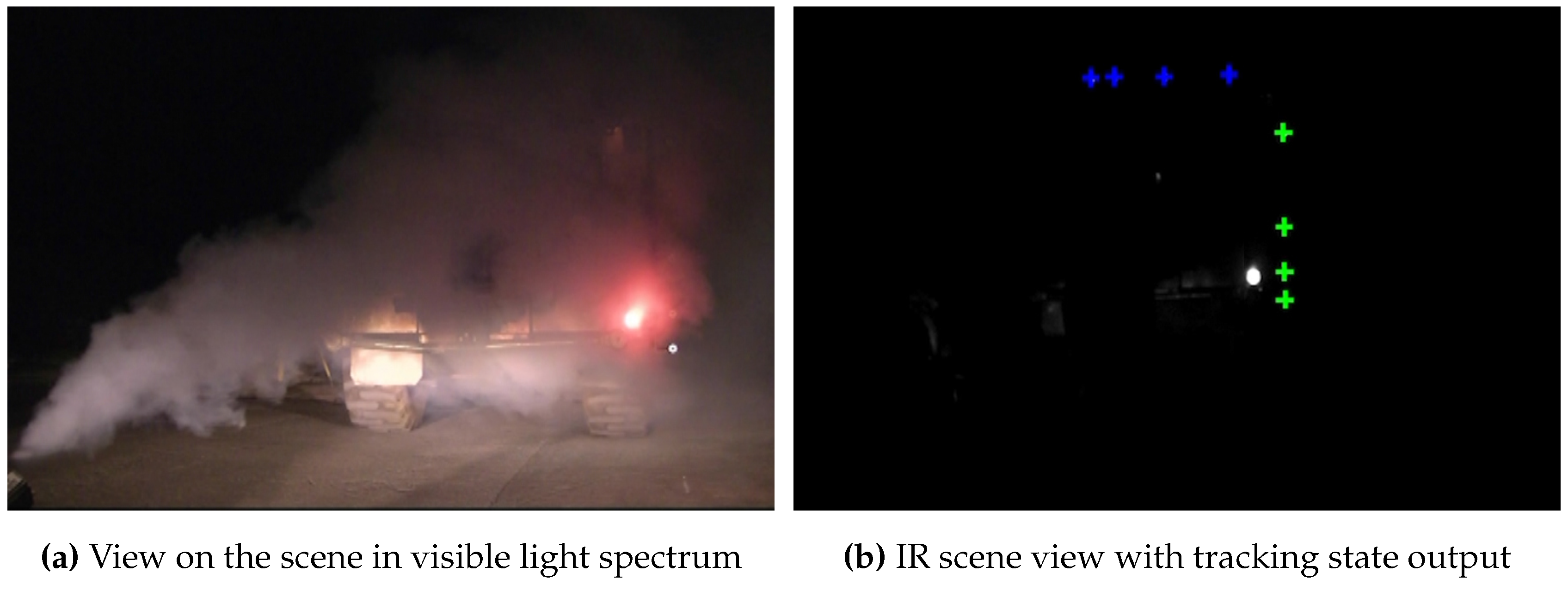
Figure 34. Both targets’ models are fully identified and tracked during fog tests.![Sensors 15 29862 g034]() Poor visibility due to fog or dust clearly reduces the measuring range and the tracking update rate. This is a common disadvantage of all optical tracking systems as well as geodetic total stations. However, as it is depicted in Figure 34, our system is able to cope even with dense fog in front of the IR-LEDs since their radiant intensity is strong enough. Tracking loss was only temporary for a few frames and system readiness was immediately and automatically reestablished as soon as visibility improves. This is a huge advantage compared to i.e., geodetic total stations, where tracking loss requires additional sighting of the target.
Poor visibility due to fog or dust clearly reduces the measuring range and the tracking update rate. This is a common disadvantage of all optical tracking systems as well as geodetic total stations. However, as it is depicted in Figure 34, our system is able to cope even with dense fog in front of the IR-LEDs since their radiant intensity is strong enough. Tracking loss was only temporary for a few frames and system readiness was immediately and automatically reestablished as soon as visibility improves. This is a huge advantage compared to i.e., geodetic total stations, where tracking loss requires additional sighting of the target.


5. Discussion
- We proposed a wide area tracking prototype that can be used for user tracking in VR/AR applications. Our results demonstrate relative 3D point accuracy mm with sub-millimeter static position jitter mm throughout the entire tracking volume, ranging from 5–30 m. We tested our system with several different target constellations, which can be detected within both camera views with rotations yaw and pitch from – as well as roll from –. To our best knowledge, no competing approach provides comparable accuracy for this range, especially not with the minimal amount of only two cameras. Therefore, the presented system goes clearly beyond state-of-the-art.
- We demonstrated the capabilities of optical tracking to be applicable to measurement scenarios beyond virtual reality environments. By providing robust hardware encasement and a simple but flexible target design, it can be used in underground scenarios such as tunnels and mines. It can be simultaneously used for a large variety of independent underground surveying tasks, such as setting out, profile control, deformation monitoring, personnel tracking for safety and machine tracking. It provides relative 3D point accuracy with a deviation of mm throughout the tracking volume of 12 m 8 m × (30–70) m. Up to 80 m, we demonstrated relative point accuracy of mm with a very high distance-invariant stability, indicated by the (sub)-millimeter static position jitter ( mm, mm, mm). Compared to state-of-the-art underground measurement systems, our approach has the capabilities of (1) automatically starting to track one or multiple targets as soon as the target is within the view of the vision system, thus manual sighting can be omitted; (2) tracking moving as well as partly occluded targets; (3) provides a flexible target design that allows general usage of various tracking and measuring tasks and (4) addresses the need for highly automated positioning systems [33,69].
5.1. Position Estimation
5.2. Calibration
6. Conclusions
Future Directions
- To enhance the estimation of external camera parameters in terms of robustness and accuracy, feature distribution in the camera image should be improved. We found an unbalanced blob coverage of the artificially generated point features especially in the vertical dimension that is caused by limited human size and the length of the calibration target as well as by the natural boundaries of the physical environment, such as the ceiling and the ground. Therefore, we will investigate concepts to extract natural features from distinct environmental structures and fuse them with the blob features to increase the distribution along the edges and in the corner of the images. This approach requires a well illuminated environment with a sufficient amount of prominent geometrical structure that might be given in a standard indoor environment. In an underground scenario, where illumination is poor and geometric structures are mostly found around the front face, natural feature extraction would not significantly enhance the feature distribution in the camera images. Here, additional single IR-LED markers that are installed throughout the volume would be an adequate solution to improve the feature distribution. These single blob features could be autonomously detected and extracted using the proposed hardware interference filtering approaches from Section 2. With these methods, we hope to achieve a more accurate calibration for stereo rigs with large baseline in both illuminated as well as poorly illuminated and non-cluttered environments.
- To extend the field of view and thereby, the horizontal and vertical tracking coverage, the relative point accuracy should be evaluated with different hardware setups using higher resolution cameras and lenses with smaller focal length. Additionally, we will examine infrared LEDs with less radiant intensity to reduce the tracking target length. Both aspects can be beneficial especially for tracking at smaller distances up to 30 m.
- To obtain absolute 3D coordinates for surveying measurement tasks, linking the camera’s coordinate system to the geo-reference coordinate system is required. The geo-reference coordinate system is obtained by geodesic measurements using a total station/theodolite. To determine the transformation matrix between the two coordinate systems, we plan to equip the tracking targets as well as additional stationary single point targets with geodesic prisms that are measured with a theodolite to obtain highly accurate geo-referenced 3D measurements.
Acknowledgments
Author Contributions
Conflicts of Interest
References
- Mossel, A.; Kaufmann, H. Wide Area Optical User Tracking in Unconstrained Indoor Environments. In Proceedings of the The 23rd International Conference on Artificial Reality and Telexistence (ICAT), Tokyo, Japan, 11–13 December 2013; pp. 108–115.
- Mossel, A.; Gerstweiler, G.; Vonach, E.; Chmelina, K.; Kaufmann, H. Vision-based Long-Range 3D Tracking, applied for Underground Surveying Tasks. J. Appl. Geodes. 2014, 8, 43–64. [Google Scholar] [CrossRef]
- Chmelina, K.; Lammer, E.; Mossel, A.; Kaufmann, H. Real-Time Machine Guidance with Tracking Cameras. In Proceedings of the 6th International Symposium High Performance Mining (AIMS), Aachen, Germany, 11–12 June 2014; pp. 679–687.
- Hightower, J.; Borriello, G. Location Systems for Ubiquitous Computing. Computer 2001, 34, 57–66. [Google Scholar] [CrossRef]
- Bowman, D.; Kruijff, E.; LaViola, J.J., Jr.; Poupyrev, I. 3D User Interfaces: Theory and Practice; Addison-Wesley: Boston, MA, USA, 2005. [Google Scholar]
- Finkenzeller, K. RFID Handbook: Radio-Frequency Identification Fundamentals and Applications; John Wiley: New York, NY, USA, 1999. [Google Scholar]
- Jiang, B.; Fishkin, K.P.; Roy, S.; Philipose, M. Unobtrusive long-range detection of passive RFID tag motion. IEEE Trans. Instrum. Meas. 2006, 55, 187–196. [Google Scholar] [CrossRef]
- Google. Indoor Maps. Available online: https://www.google.com/intl/en/maps/about/explore/mobile/ (accessed on 12 January 2013).
- SensionLab. Indoor Positioning and Navigation. Available online: http://www.senionlab.com (accessed on 1 December 2013).
- IndooRs. Location Tracking. Available online: http://indoo.rs/ (accessed on 1 December 2013).
- Nissanka, B.P. The Cricket Indoor Location System. Ph.D. Thesis, Massachusetts Institute of Technology, Cambridge, MA, USA, 2005. [Google Scholar]
- Hazas, M.; Ward, A. A novel broadband ultrasonic location system. Ubi. Comp. 2002, 2498, 264–280. [Google Scholar]
- Ijaz, F.; Yang, H.K.; Ahmad, A.W.; Lee, C. Indoor Positioning: A Review of Indoor Ultrasonic Positioning systems. In Proceedings of 15th International Conference on Advanced Communication Technology (ICACT), Pyeongchang, Korea, 27–30 January 2013; pp. 1146–1150.
- Ubisense. Real-Time Localization Systems. Available online: http://www.ubisense.net (accessed on 1 December 2013).
- Stelzer, A.; Pourvoyeur, K.; Fischer, A. Concept and application of LPM: A novel 3-D local position measurement system. IEEE Trans. Microw. Theory Tech. 2004, 42, 2664–2669. [Google Scholar] [CrossRef]
- Skolnik, M.I. Introduction to Radar Systems. In Radar Handbook; McGraw-Hill: New York, NY, USA, 1962; p. 2. [Google Scholar]
- Hartley, R.; Zisserman, A. Multiple View Geometry in Computer Vision; Cambridge University Press: Cambridge, UK, 2004. [Google Scholar]
- InserSense. IS-1200 System. Available online: http://www.intersense.com/pages/21/13 (accessed on 10 December 2014).
- Kato, H.; Billinghurst, M. Marker Tracking and HMD Calibration for a Video-based Augmented Reality Conferencing System. In Proceedings of the 2nd IEEE and ACM International Workshop on Augmented Reality (IWAR), San Francisco, CA, USA, 20–21 October 1999; pp. 85–94.
- Qualcomm Inc. Vuforia Software, v3.0. Available online: https://developer.vuforia.com (accessed on 10 October 2014).
- Vicon. Motion Capture. Available online: http://www.vicon.com/ (accessed on 1 December 2013).
- ART. Advanced Real Time Tracking. Available online: http://www.ar-tracking.com/products/tracking-systems/systems-overview/ (accessed on 9 December 2015).
- Pintaric, T.; Kaufmann, H. Affordable Infrared-Optical Pose-Tracking for Virtual and Augmented Reality. In Proceedings of the Workshop on Trends and Issues in Tracking for Virtual Environments Workshop, IEEE VR, Charlotte, NC, 11 March 2007; pp. 44–51.
- Pintaric, T.; Kaufmann, H. Iotracker. Available online: http://www.iotracker.com (accessed on 12 January 2013).
- WorldViz. PPT E Motion Tracking. Available online: http://www.worldviz.com/products/ppt/ (accessed on 1 December 2014).
- NaturalPoint Inc. OptiTrack. Available online: http://www.naturalpoint.com/optitrack/ (accessed on 12 January 2013).
- Fuchser, H.J. Determining Convergences by photogrammetric Means. Tunnel 1998, 17, 38–42. [Google Scholar]
- Accurex. AICON DPA-Pro System. Available online: http://www.accurexmeasure.com/dpapro.htm (accessed on (accessed on 10 December 2013).
- Geodata Group. Gripper Camera—System Description and Data Sheet, Technical Report; Geodata GmbH: Leoben, Austria, 2013. [Google Scholar]
- Kavanagh, B. Surveying Principles and Applications, 8th ed.; Prentice Hall Inc.: Upper Saddle River, NJ, USA, 2008. [Google Scholar]
- Kavanagh, B. Surveying with Construction Applications, 7th ed.; Prentice Hall Inc.: Upper Saddle River, NJ, USA, 2005. [Google Scholar]
- Shortis, M.R.; Fraser, C.S. A review of close range optical 3D measurement. In Proceedings of 16th National Surveying Conference, Barossa Valley, Australia, 5–9 November 1990.
- Chmelina, K. Laserscanning in Underground Construction: State and Future of a Multi-Purpose Surveying Technology. In Proceedings of Austria-China International Symposium on Challenging Tunnel Construction, Vienna University of Technology, Vienna, Austria, 2–5 May 2007.
- Chmelina, K. Tunnel Laser Scanning, Current Systems, Applications and Research Activities. In Proceedings of the ITA-AITES World Tunnel Congress, Agra, India, 19–25 September 2008; pp. 86–92.
- Chmelina, K.; Rabensteiner, K. Laser Scanning Technology in Underground Construction. In Proceedings of the Jubilee International Scientific and Technical Conference on Tunnel and Metro Constructions, Sofia, Bulgaria, 28–29 January 2008.
- Chmelina, K.; Jansa, J.; Hesina, G.; Traxler, C. A 3-D Laserscanning System and Scan Data Processing Method for the Monitoring of Tunnel Deformations. J. Appl. Geodes. 2012, 6, 177–185. [Google Scholar]
- Leica Geosystems. The Leica Absolute Interferometer: A New Approach to Laser Tracker Absolute Distance Meters, Technical Report; Leica Geosystems: Unterentfelden, Switzerland, 2008. [Google Scholar]
- Leica Geosystems. Absolute Tracker AT901. Available online: http://www.leica-geosystems.com/en/eica-Absolute-Tracker-AT901_69047.htm (accessed on 12 February 2013).
- Leica Geosystems. T-Probe. Available online: http://www.leica-geosystems.com (accessed on 12 February 2013).
- Mossel, A.; Pintaric, T.; Kaufmann, H. Analyse der Machbarkeit und des Innovationspotentials der Anwendung der Technologie des Optical Real-Time Trackings für Aufgaben der Tunnelvortriebsvermessung, Technical Report; Institute of Software Technology and Interactive Systems, Vienna University of Technology: Vienna, Austria, 2008. (In German) [Google Scholar]
- Faugeras, O. Three-Dimensional Computer Vision: A Geometric Viewpoint.; MIT Press: Cambridge, MA, USA, 1993. [Google Scholar]
- Pintaric, T.; Kaufmann, H. A Rigid-Body Target Design Methodology for Optical Pose-Tracking Systems. In Proceedings of the ACM Symposium on Virtual Reality Software and Technology (VRST), Bordeaux, France, 27–29 October 2008; pp. 73–76.
- Sturm, P.; Maybank, S. On Plane-based Camera Calibration: A general Algorithm, Singularities, Applications. In Proceedings of the IEEE Conference on Computer Vision and Pattern Recognition, Fort Collins, CO, USA, 23–25 June 1999; pp. 432–437.
- Zhang, Z. A Flexible new Technique for Camera Calibration. IEEE Trans. Pattern Anal. Mach. Intell. 2000, 22, 1330–1334. [Google Scholar] [CrossRef]
- Lasenby, J.; Stevenson, A. Using Geometric Algebra for Optical Motion Capture. In Geometric Algebra: A Geometric Approach to Computer Vision, Neural and Quantum Computing, Robotics and Engineering Pages; Springer (Birkhauser): Berlin, Germany, 2001; pp. 147–169. [Google Scholar]
- Svoboda, T.; Martinec, D.; Pajdla, T. A convenient multi-camera self-calibration for virtual environments. Presence Teleoperators Virtu. Environ. 2005, 14, 407–422. [Google Scholar] [CrossRef]
- Liu, R.; Zhang, H.; Liu, M.; Xia, X.; Hu, T. Stereo Cameras Self-Calibration Based on SIFT. In Proceedings of IEEE International Conference on Measuring Technology and Mechatronics Automation, Zhangjiajie, China, 11–12 April 2009; pp. 352–355.
- Puwein, J.; Ziegler, R. Robust multi-view camera calibration for wide-baseline camera networks. In Proceedings of IEEE Workshop on Applications of Computer Vision (WACV), Kona, HI, USA, 15–17 January 2011; pp. 321–328.
- Dang, T.; Hoffmann, C.; Stiller, C. Continuous stereo self-calibration by camera parameter tracking. IEEE Trans. Image Process. 2009, 18, 1536–1550. [Google Scholar] [CrossRef] [PubMed]
- Jaspers, H.; Schauerte, B.; Fink, G. Sift-based Camera Localization using Reference Objects for Application in Multi-camera Environments and Robotics. In Proceedings of International Conference on Pattern Recognition Applications and Methods (ICPRAM), Vilamoura, Portugal, 6–8 February 2012; pp. 330–336.
- Longuet-Higgins, H. A Computer Alorithm for Reconstructing a Scene from Two Projections. Nature 1981, 293, 133–135. [Google Scholar] [CrossRef]
- Dorfmüller-Ulhaas, K. Optical Tracking: From User Motion To 3D Interaction. Ph.D. Thesis, Vienna University of Technology, Vienna, Austria, 2002. [Google Scholar]
- Bouguet, J.Y. Camera Calibration Toolbox for Matlab. Available online: http://www.vision.caltech.edu/bouguetj/calib_doc/index.html (accessed on 9 December 2015).
- van Liere, R.; Mulder, J.D. Optical tracking using projective invariant marker pattern properties. In Proceedings of IEEE Virtual Reality, Los Angeles, CA, USA, 22–26 March 2003; pp. 191–198.
- van Rhijn, A. Configurable Input Devices for 3D Interaction using Optical Tracking. Ph.D. Thesis, Technische Universiteit Eindhoven, Eindhoven, The Netherlands, 2007. [Google Scholar]
- Gonzales, R.C.; Woods, R.E. Digital Image Processing; Prentice Hall: Upper Saddle River, NJ, USA, 2002; p. 587ff. [Google Scholar]
- Smit, F.A.; van Rhijn, A.; van Liere, R. GraphTracker: A Topology Projection Invariant Optical Tracker. In Proceedings of the 12th Eurographics Conference on Virtual Environments, Lisbon, Portugal, 8–10 May 2006; pp. 63–70.
- Santos, P.; Stork, A. Ptrack: Introducing a novel iterative geometric pose estimation for a marker-based single camera tracking system. In Proceedings of the IEEE Virtual Reality, Alexandria, VA, USA, 25–29 March 2006; pp. 149–156.
- Loaiza, M.; Raposo, A.; Gattass, M. A novel optical tracking algorithm for point-based projective invariant marker patterns. Adv. Visual Comput. 2007, 4841, 160–169. [Google Scholar]
- Triggs, B.; McLauchlan, P.F.; Hartley, R.; Fitzgibbon, A. Bundle adjustment—A modern synthesis. In Vision Algorithms: Theory and Practise; Triggs, W., Zisserman, A., Szeliski, R., Eds.; Springer: Berlin, Germany, 2000; Volume 34099, pp. 298–372. [Google Scholar]
- Quan, L.; Lan, Z. Linear N-point camera pose determination. IEEE Trans. Pattern Anal. Mach. Intell. 1999, 21, 774–780. [Google Scholar] [CrossRef]
- Kalman, R. A new Approach to Linear Filtering and Prediction Problems. J. Basic Eng. 1960, 82, 35–45. [Google Scholar] [CrossRef]
- Welch, G.; Bishop, G. An Introduction to the Kalman Filter, Technical Report; University of North Carolina: Chapel Hill, NC, USA, 1995. [Google Scholar]
- Arduino. Arduino IDE. Available online: https://www.arduino.cc/ (accessed on 9 December 2015).
- AIA. GigE Vision. Available online: http://www.visiononline.org/ (accessed on 9 December 2015).
- Vasylevska, K.; Kaufmann, H. Influence of Vertical Navigation Metaphors on Presence. In Proceedings of 15th International Conference on Presence (ISPR 2014), Vienna, Austria, 17–19 March 2014; pp. 205–212.
- Hartley, R.; Sturm, P. Triangulation. Comput. Vis. Image Underst. 1997, 68, 146–157. [Google Scholar] [CrossRef]
- Lu, F.; Hartley, R. A Fast Optimal Algorithm for L2 Triangulation. In Computer Vision—ACCV 2007; Springer: Berlin, Germany, 2007; pp. 279–288. [Google Scholar]
- Rodríguez, J. Vision 2030, Technical Report; European Construction Technology Platform (ECTP): Maastricht, The Netherlands, 2005. [Google Scholar]
- MathWorks. MATLAB ImageProcessingToolbox. Available online: http://www.mathworks.com/help/toolbox/images/ (accessed on 12 January 2013).
© 2015 by the authors; licensee MDPI, Basel, Switzerland. This article is an open access article distributed under the terms and conditions of the Creative Commons by Attribution (CC-BY) license (http://creativecommons.org/licenses/by/4.0/).
Share and Cite
Mossel, A. Robust 3D Position Estimation in Wide and Unconstrained Indoor Environments. Sensors 2015, 15, 31482-31524. https://doi.org/10.3390/s151229862
Mossel A. Robust 3D Position Estimation in Wide and Unconstrained Indoor Environments. Sensors. 2015; 15(12):31482-31524. https://doi.org/10.3390/s151229862
Chicago/Turabian StyleMossel, Annette. 2015. "Robust 3D Position Estimation in Wide and Unconstrained Indoor Environments" Sensors 15, no. 12: 31482-31524. https://doi.org/10.3390/s151229862
APA StyleMossel, A. (2015). Robust 3D Position Estimation in Wide and Unconstrained Indoor Environments. Sensors, 15(12), 31482-31524. https://doi.org/10.3390/s151229862