Next Article in Journal
Reusable EGaIn-Injected Substrate-Integrated-Waveguide Resonator for Wireless Sensor Applications
Next Article in Special Issue
Toward Higher-Order Mass Detection: Influence of an Adsorbate’s Rotational Inertia and Eccentricity on the Resonant Response of a Bernoulli-Euler Cantilever Beam
Previous Article in Journal
High-Temperature SAW Wireless Strain Sensor with Langasite
Previous Article in Special Issue
Lipid Multilayer Grating Arrays Integrated by Nanointaglio for Vapor Sensing by an Optical Nose
 
 
Correction published on 27 May 2016, see Sensors 2016, 16(6), 781.
Article

Modelling the Size Effects on the Mechanical Properties of Micro/Nano Structures

1
Department of Mechanical Engineering, Isfahan University of Technology, Isfahan 84156-83111, Iran
2
Advanced NEMS Group, École Polytechnique Fédérale de Lausanne (EPFL), Lausanne CH-1015, Switzerland
3
Department of Mechanical Engineering, Urmia University, Urmia 57561-51818, Iran
*
Authors to whom correspondence should be addressed.
Sensors 2015, 15(11), 28543-28562; https://doi.org/10.3390/s151128543
Submission received: 7 August 2015 / Revised: 20 October 2015 / Accepted: 26 October 2015 / Published: 11 November 2015
(This article belongs to the Special Issue Nanomechanics for Sensing and Spectrometry)

Abstract

:
Experiments on micro- and nano-mechanical systems (M/NEMS) have shown that their behavior under bending loads departs in many cases from the classical predictions using Euler-Bernoulli theory and Hooke’s law. This anomalous response has usually been seen as a dependence of the material properties on the size of the structure, in particular thickness. A theoretical model that allows for quantitative understanding and prediction of this size effect is important for the design of M/NEMS. In this paper, we summarize and analyze the five theories that can be found in the literature: Grain Boundary Theory (GBT), Surface Stress Theory (SST), Residual Stress Theory (RST), Couple Stress Theory (CST) and Surface Elasticity Theory (SET). By comparing these theories with experimental data we propose a simplified model combination of CST and SET that properly fits all considered cases, therefore delivering a simple (two parameters) model that can be used to predict the mechanical properties at the nanoscale.

1. Introduction

Due to their small sizes, micro- and nano-mechanical systems (M/NEMS) hold tremendous promise for novel, versatile and very sensitive devices for different applications ranging from mass detection [1,2] to frequency synthesis [3,4,5,6], including bio- [7,8], force [9] and light detection [10,11]. In addition to being incredibly sensitive, they also show a very low power consumption, and a very small footprint, which is beneficial for miniaturization. The latter is particularly important for applications as mechanical switches [12,13,14], where a large number of elements will be necessary to perform complex logic operations. A paramount condition for any eventual application of M/NEMS is the ability to predict the device characteristics at the design level. This, among other things, implies that one should be able to predict the structural and mechanical properties of the material used to fabricate any device.
The small dimensions of these M/NEMS can, however, pose a serious challenge as experimental characterization has shown in the past few years how the material properties depend on the size (e.g., thickness) of the layer used to fabricate the device.
M/NEMS have dimensions that can range in length from 1  μm to 1000  μm and thicknesses or diameters typically in the range of few μm down to 25  nm or even sub-nm regime [15], which overlap with the critical length scales in materials. As a consequence, the physical properties of nanoscale materials such as mechanical, electrical, thermal and magnetic properties can be different from the bulk values. This, of course, is both a limitation and an opportunity, as we can use micro/nanostructures such as nanowires and nanobeams as excellent systems for studying size effect in material properties and behavior at the small scale. Among the different properties that arise when reducing the size of the any device we can find changes in resistivity [16,17], magnetic frustration [18], thermal conductivity [19], and mechanical properties. This latter case includes anomalous behavior of nonlinear response [20] and the quality factor [21], the appearance of nonlinear damping [22], and the variation of the Young’s modulus.
Young’s Modulus is a fundamental mechanical property that affects stiffness, frequency and reliability of M/NEMS. For macroscopic structures it is considered as a bulk material property, independent of size. However, at the micro/nanoscale researchers have observed that the behavior of mechanical structures cannot be explained using macroscopic theory and a constant value of the Young’s modulus. Indeed, it is not only different from the bulk value, but it is also size-dependent in most cases. In this paper we focus on the study of this alleged Young’s modulus size dependence, we first give an overview of the state of the art about experimental measurement of the Young’s modulus, then we present the typical theories used to explain this size effect and we apply them to the selected cases from the literature, concluding that none of the theories alone can actually predict the size dependence for all samples. We therefore propose a combined model which considers the residual stress in the material, the microstructure of the bulk and also the surface properties of M/NEMS.

2. Size Effect on the Young’s Modulus of Materials

We have extensively researched the literature for available experimental data on the size effect of the Young’s modulus. We have done so restricting ourselves to experiments that analyze the Young’s modulus using various techniques (e.g., resonant frequency, point-load deflection) but always through the bending rigidity of different M/NEMS. Table 1 summarizes the analyzed data. In almost every case, the authors extract a parameter we will call effective Young’s modulus E e f f , i.e., the Young’s modulus that can be calculated when considering classical beam theory and not a size dependence of the material properties. It is this magnitude, E e f f , the one which tendency we highlight in Table 1, whether increasing when size reduces (I, stiffening effect), decreasing (D, softening effect) or being constant (C).
In order to obtain thin structures experimentally, researchers were originally limited to metals and polymers that could be deposited in a controlled manner, which is why the first experiments at the microscale were done on those materials [23,24]. Fleck et al. [25] did experiments on copper wires with diameters ranging from 170  μm to 12  μm , observing an increase in the stiffness. Many of these original experiments were performed using either torsional loads or indentation, and thus are not included in Table 1.
Table 1. Size dependency in micro/nano structures.
ReferenceShapeMaterialMorphologyTrend a
Lam et al. (2003) [26]Clamped-FreeEpoxyAmorphousI
Cuenot et al. (2003) [27,28]Clamped-ClampedPPyAmorphousI
Cuenot et al. (2004) [28,29]Clamped-ClampedPbCrystallineI
Cuenot et al. (2004) [28,29]Clamped-ClampedAgCrystallineI
McFarland et al. (2005) [30]Clamped-FreePolypropyleneAmorphousI
Wu et al. (2006) [31]Clamped-ClampedAgCrystallineI
Jing et al. (2006) [32]Clamped-ClampedAgCrystallineI
Shin et al. (2006) [33]Clamped-ClampedElectroactive polymerAmorphousI
Liu et al. (2006) [34]Clamped-FreeWO3CrystallineI
Tan et al. (2007) [35]Clamped-ClampedCuOCrystallineI
Stan et al. (2007) [36]All fixedZnOCrystallineI
Chen et al. (2007) [37]Clamped-FreeGaN [0001]CrystallineI
Sun et al. (2008) [38]Clamped-ClampedPolycaprolactoneAmorphousI
Ballestra et al. (2010) [39]Clamped-FreeAuPolycrystallineI
Li et al. (2003) [40]Clamped-FreeSiCrystallineD
Nilsson et al. (2004) [41]Clamped-FreeCrPolycrystallineD
Nam et al. (2006) [42]Clamped-FreeGaN [120]CrystallineD
Gavan et al. (2009) [43]Clamped-FreeSiNAmorphousD
Namazu et al. (2000)[44]Clamped-ClampedSiCrystallineC
Wu et al. (2005) [45]Clamped-ClampedAuAmorphousC
Ni et al. (2006) [46]Clamped-ClampedGaNCrystallineC
Chen et al. (2006) [47]Clamped-ClampedAgAmorphousC
Chen et al. (2006) [48]Clamped-FreeZnOCrystallineC
Ni et al. (2006) [49]Clamped-ClampedSiO2AmorphousC
a I = increase, D = decrease, C = Constant.
A couple of interesting examples deal with the study of polymeric structures. In the first case, McFarland and Colton showed [30] that the E e f f measured from bending stiffness experiments increases with thickness reduction, while indentation measurements did not show any dependence on thickness. In a parallel and independent study, Lam et al. [26] studied the elastic response of epoxy clamped-free beams between 12.5  μm and 50  μm under both bending and elongation tests. They found that the results of the latter experiments pointed to a constant E e f f with respect to the size; whereas the results from bending tests showed an increase in the E e f f . Sun et al. [38] studied polymeric nanofibers and obtained a very similar result than the one just described, where uniaxial tensile measurements showed no dependence on size but bending experiments did show an increase of E e f f . One main conclusion from these papers is that in those cases the size effect was not on the material property itself but rather on the bending stiffness, which we will further analyze in the discussions.
Further development in micro- and nano-fabrication techniques has allowed researchers to probe thinner and narrower structures of a variety of different materials. Shin et al. [33] observed that the elastic modulus of an electroactive polymer increases with decreasing size, if the diameter of the fiber is less than 100 nanometers. Chen et al. [37] investigated mechanical elasticity of GaN nanowires with hexagonal cross sections in a diameter range of 57–135 nm, showing an increase of E e f f with decreasing diameter. In fact, this tendency is the most common of the cases we have found. We can see the same in experiments on other materials like carbon nanotubes [50] and Ag and Pb nanowires [29], where E e f f increases dramatically with decreasing diameter.
On the other hand, as it is proved by other experiments [40,41,42,43], E e f f can also show the opposite dependence with thickness, or just remaining constant [45,51]. Interestingly, there are some materials for which different types of tendencies have been reported, as for example GaN [37,42,46] or ZnO [36,48].

3. Theoretical Models for Size Effect

The experimental works described in the previous section defy the classical understanding of elastic behavior of structures and materials, where the Young’s modulus is a material property that does not depend on size and structures follow standard Hooke’s law and Euler-Bernoulli theory. As a consequence, several theories have been developed to explain the experimental results by including additional parameters into consideration. Here we will describe succinctly the five predominant theories to explain these size effects: residual stress (RST), couple stress (CST), grain boundaries (GBT), surface stress (SST), and surface elasticity (SET). The formulas are developed in the case of a rectangular cross section (see Figure 1) but a similar result can be found for any other cross section, just with other proportionality coefficients.
The literature also contains a number of works on quantitative theoretical investigations using atomistic simulations [52,53,54,55] or continuum theory modifications [29,56,57] to get the overall mechanical behavior of a micro/nanostructure. Some of the works study nonlinear effects [53], surface stresses [29,53,54,58], surface elasticity [32,56,57], grain boundaries [59,60], etc. In any case, to check the validity of the simulations or in case they are not available, the different theories are always compared against the experimental results therefore estimating the different parameters in the model via fitting to the results, which is what we do in the following section for most of the papers in Table 1.
Figure 1. Schematic of a clamped-free beam. Cantilever with rectangular cross section where the width is denoted by b , the thickness by h and the length by L . The axis x and z are also marked with the positive sense.
Sensors 15 28543 g001

3.1. Residual Stress Theory

The most straightforward of all the models we present in this paper is the one that accounts for the contribution to the stiffness of the residual (or intrinsic) stress in the material (RST). Deposited or grown thin films (metals, dielectrics, polymers, …) [61], bottom-up grown nanowires [62], two dimensional materials [63],… residual stress is a consequence of the different micro- and nanofabrication processes that the wafers usually undergo [64]. This residual stress remains in the structures when the clamping conditions allow it (e.g., clamped-clamped beams), and thus needs to be considered when modelling the mechanical response of the structures. Indeed, the effect of residual stress can be seen in many examples in the literature, from the buckling of mechanical structures [62,65], till extremely high quality factors in resonators [21,66,67,68], including the stiffness and thus frequency dependence of resonators [5,66,69,70,71,72,73].
Taking the particular example of a clamped-clamped structures, we can write its total elastic energy when it is deformed as the sum of the energy contributions from structure bending and residual stress.
The elastic energy U b e n d i n g in a structure without the residual stress effect can be expressed as:
U b e n d i n g = 0 L M ( x ) 2 2 E I d x = E I 2   0 L ( 2 w ( x ) x 2 ) 2 d x = E I 2   0 L w ( x ) 2 d x
where E is the Young’s modulus of the bulk material, I is the second moment of inertia, M is the bending moment and w is the out of plane deformation that depends on the position along the axis. The potential energy because of residual stress ( E r ) can be defined as:
U r = 0 L N r d ( Δ L ) N r 2 0 L ( w ( x ) x ) 2 d x = σ 0 b h 2 0 L w ( x ) 2 d x
where σ 0 is the residual stress in the material and N r = σ 0 b h is the longitudinal force that arises from said stress. The total energy in the structure, if this is regarded as a homogeneous material with an effective Young’s modulus E e f f , then the total elastic energy U t o t can be expressed as:
U t o t = U b e n d i n g + U r = 0 L M ( x ) 2 2 E e f f I d x = E e f f I 2   0 L w ( x ) 2 d x
And therefore we can write:
E e f f = E + σ 0 b h I 0 L w ( x ) 2 d x 0 L w ( x ) 2 d x = E + 12 σ 0 h 2 0 L w ( x ) 2 d x 0 L w ( x ) 2 d x
Assuming a point load (F) applied in the middle of the clamped-clamped structure, the deflection equation for the first half of the beam can be expressed by Equation (5), and the deflection is symmetric for the second half:
w ( 0 x L 2 ) = 4 x 2 ( 3 L 4 x ) L 3 w m a x
where w m a x is the maximum deflection of the beam. Equation (5) allows us to calculate the integrals in Equation (4) and obtain the following formula for E e f f in the case of a clamped-clamped structure:
E e f f = E + 3 10 σ 0 ( L h ) 2
Importantly, these equations strongly depend on the boundary conditions of the structure, as these might release part of the stress σ 0 (e.g., cantilevers). In addition, the dependence of the stress-related term is proportional to ( L / h ) 2 , which implies different magnitude of the effect for the same thickness.

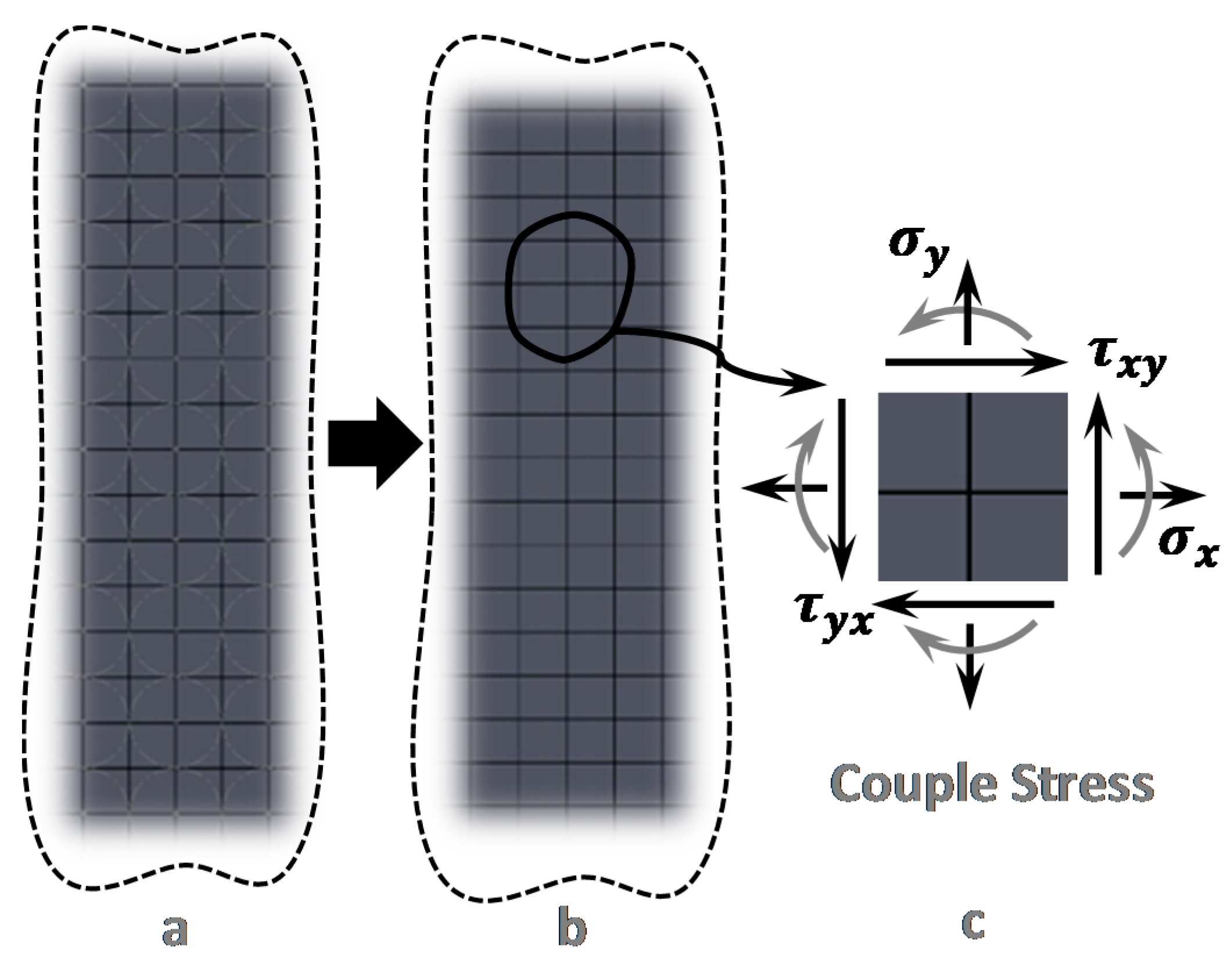
3.2. Couple Stress Theory

While the results of elementary theories like Euler-Bernoulli do match experimental results in many situations, these theories assume that the constitutive model is independent of length scale, e.g., Hooke’s Law. This assumption works well for macro-scale structures, but it was realized long ago that additional parameters are needed to relate stress and strain at the microscale [74,75,76].
The idea of couple stress was introduced at the end of the 19th century, and the beginning of the 20th. One of the first accounts that can be found was reported by the Cosserat brothers [77,78] who introduced their theory taking into account not only the local translational motion of a point within a material body (as assumed by classical elasticity, i.e., Hooke’s Law) but also the local rotation of that point. This is implemented in the couple stress theory (CST) by introducing a torque per unit area (couple stress) as well as a force per unit area, which is well known to normal stress and shear stress in classical elasticity. A theory that is equivalent to this is strain gradient [79,80].
The general idea of the microstructural and micromorphic elasticity theories [74,81,82] is that the points of the continuum associated with a microstructure of finite size can deform macroscopically (yielding the classical elasticity case) as well as microstructurally, producing the length scale effect. In other words, the behavior of many solid materials is dependent on microscale length parameters and on additional microstructural degrees of freedom. This concept can be qualitatively illustrated by considering a simple lattice model of materials as shown in Figure 2.
Let us calculate now the modification that CST brings to Euler-Bernoulli theory, so that we can extract a formula for E e f f . A schematic of a simple cantilever is shown in Figure 1 to illustrate coordinates. In Figure 1, the x-axis coincides with the centroidal axis of the undeformed beam and the z-axis is the axis of symmetry. L , b and h are respectively length, width and thickness of the micro/nano beam.
Figure 2. Schematic of the microstructure that justifies Couple Stress Theory (CST). Simple lattice model of heterogeneous materials illustrating dependency of material behavior on couple stress; (a) Microstructure of a heterogeneous elastic material; (b) Equivalent Lattice Model; (c) Normal and shear stresses on a typical in-plane element in presence of the couples stress.
Sensors 15 28543 g002
In the linear couple stress theory the strain energy density of a deformed body is assumed to depend on strain ε   and rotation gradient κ . Using index notation, the constitutive equations for the strain energy density can be written as [83]:
e s = 1 2 λ ε i i ε j j + μ ε i j ε i j + 2 η κ i j κ i j + 2 η κ i j κ j i
where λ and μ are the two Lame’s constants of classical elasticity, whereas η and η are two non-classical Lame-type material constants which introduce the couple stress effects. i ,   j ,   k are indices that vary from 1 to 3; representing the variables in x ,   y ,   z directions in Cartesian coordinates, respectively. The strain energy E s and the kinetic energy E k in a deformed isotropic linearly-elastic material occupying a volume V are defined as follows:
E s = V e s d v ;   E k = 1 2 V ρ u ˙ i u ˙ i d v
where u ˙ i is the velocity in the i direction. The non-zero displacement and rotation components of an Euler-Bernoulli beam (see Figure 1), disregarding the mid-point displacement in the x direction, can be expressed as:
w = w ( x , t ) ,   u = z w x ,   θ y = w x
where u ,   w are the x ,   z components of the displacement vector, respectively and θ y is the component of the rotation vector in the x z plane. In view of Equation (9), the non-zero components of the symmetric strain tensor and the components of the asymmetric rotation-gradient tensor can be written as follows:
ε x x = u x ,   ε y y = ε z z = ν u x ,   κ x y = 2 w x 2
where ν is the Poisson’s ratio of the beam material. By substituting Equation (10) into Equation (7), we obtain:
e s = 1 2 E ( u x ) 2 + 2 η ( 2 w x 2 ) 2
where E is the Young’s modulus of the material. Only one non-classical material constant appears in Equation (11), which is defined as η = μ 2 [75], where is the material length scale parameter and μ is the shear modulus of the material which is equal to E / ( 2 ( 1 + ν ) ) . Applying the Hamilton principle we can obtain the following equation for the free vibration of a micro/nano beam:
( E I + 4 μ A 2 ) 4 w x 4 + ρ A 2 w t 2 = 0
From Equation (12) it becomes clear that the bending rigidity of the beam is E I + 4 μ A 2 , so E e f f is:
E e f f = E + 24 E 1 + ν ( h ) 2
As it can be seen in Equation (13), CST is only able to predict a stiffening effect when reducing the size. This indeed includes many of the works in Table 1, but it is evident that this theory cannot be applied to every material. In addition, the length scale parameter cannot be easily computed and the only way to extract it is via fitting to the experimental data. The main problem is whether this parameter is constant or also depends on the thickness of the material. For the sake of simplicity, we assume that it is a characteristic parameter that depends only on the material and its fabrication process, thus making it a constant fitting parameter for every separate set of experiments. Importantly, CST is the only theory able to predict and/or explain the results described in the previous section, i.e., that some structures would show a stiffening behavior in bending experiments, whereas no change for tensile experiments [26,30,38]. In fact, RST can also explain such behavior for clamped-clamped beams, but not for clamped-free beams.

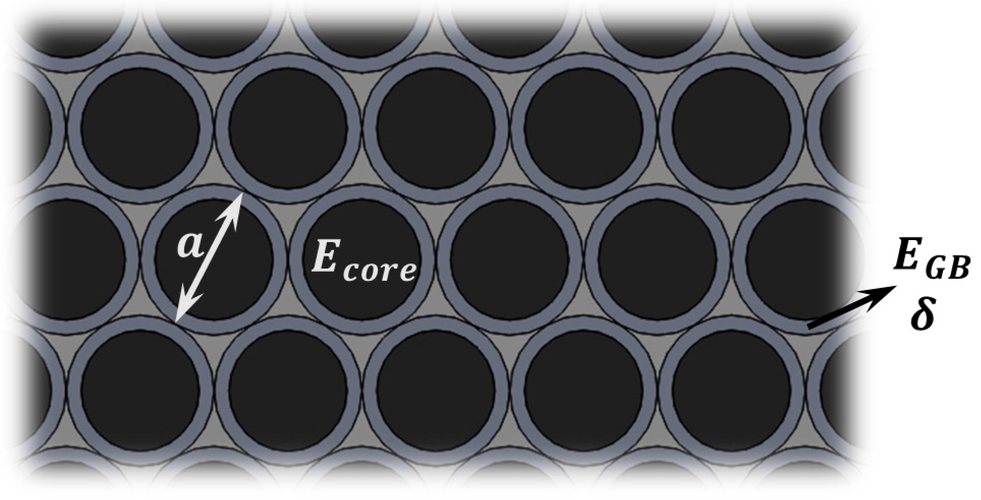
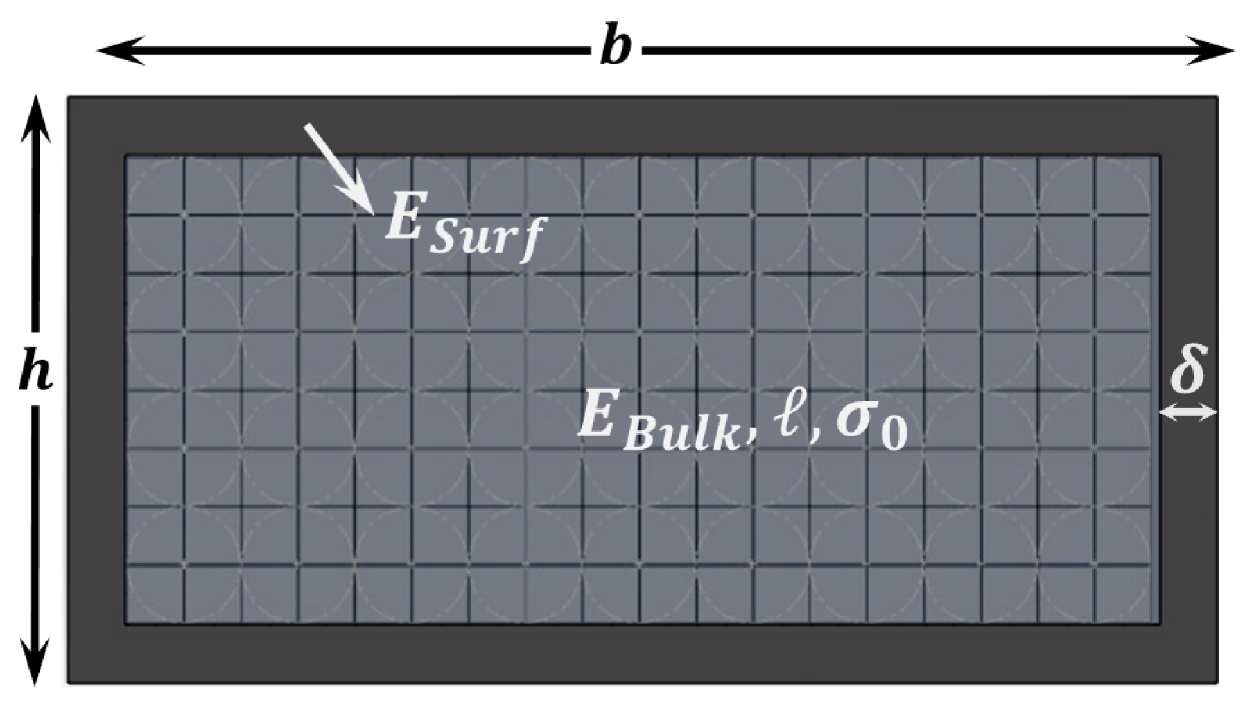
3.3. Grain Boundary Theory

Another theory for explaining the size effect in materials is based on the fact that grain boundaries might have different material properties than the core of the grains, we call it grain boundary theory (GBT). Atoms which are in grain boundaries are in contact with their neighbors which have a different orientation, so the energy level of those atoms in boundaries can be different than atoms inside the grains which are in contact with similar atoms with the same orientation; hence leading to different mechanical properties.
In this model grains are modeled with a thin surface layer (of thickness δ , see Figure 3) and Young’s modulus E G B , while E c o r e is the Young’s modulus for the core part of the grains, and the overall diameter is a (see Figure 3) [59]. Some modifications of this approximation can also be considered [60], but do not affect the dependence on the structure dimensions.
Figure 3. Grain Boundary Theory (GBT). Schematic showing the nanoscopic view of a grained material. Each grain has a diameter a and a thin shell around them with thickness δ , and both sections have in general different Young’s moduli.
Sensors 15 28543 g003
This model only gains importance when the layer thickness is only a few grains, which is when the effect of having a finite number of grain boundaries cannot be neglected. Considering a rectangular cross-section beam like the one in Figure 1, and assuming that the grain size remains constant as the material thickness reduces, we can use composite theory to calculate an approximate formula for the effective Young’s modulus for bending, which is given by Equation (14):
E e f f = 24 h 3 [ c 1 a ( h 2 a ) + c 2 a n = 1 h 2 a ( n 1 2 ) 2 ]
where:
c 1 = π 8 [ δ ( a 3 3 δ a 2 ) E GB + a 8 ( a 3 + 24 a δ 2 8 δ a 2 ) E c o r e ] c 2 = π [ δ ( a δ ) E GB + a 4 ( a 4 δ ) E c o r e ]
which in the case of very narrow shell ( δ a ) leads to a dependence with thickness of the type E e f f 1 / h 2 .

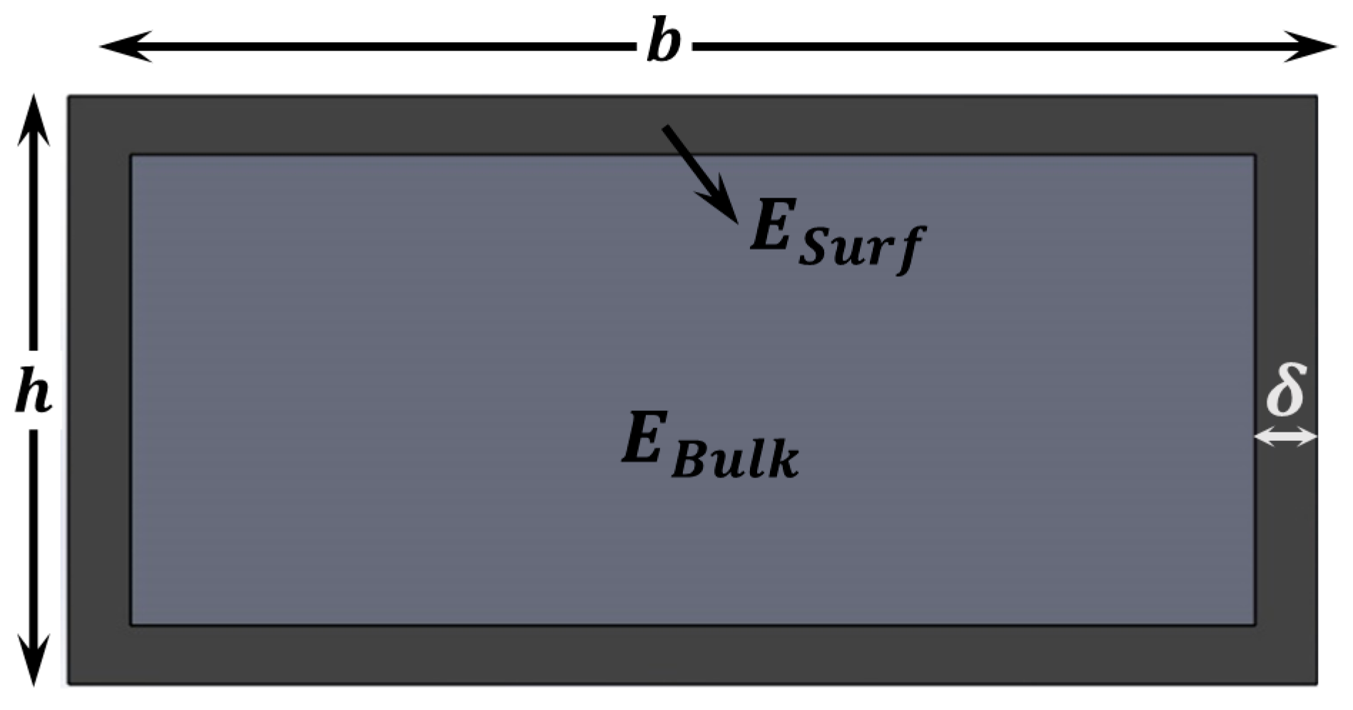
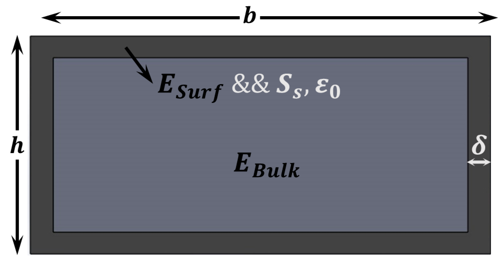
3.4. Surface Elasticity Theory

The theories that have been presented up to now can be visible at relatively thick structures, as this will depend on the grain size (GBT), the length scale parameter (CST) or the residual stress and length (RST). However, when thickness is reduced down to the nanoscale, the surface to volume ratio starts to increase dramatically and we do need to take into account surface effects. This has been done predominantly in two ways: Surface Elasticity Theory (SET) and Surface Stress Theory (SST).
The former of these theories (SET) is based on the fact that the nature of the chemical bond and the equilibrium interatomic distances at the surface are different from that inside the bulk [84], that is to say the coordination number of atoms close to the surface is lower than for bulk atoms. Therefore superficial mechanical properties are different from bulk material properties. Another justification can be found as a consequence of the micro- and nano-fabrication of the devices. Atoms diffusion into the layer, adsorption of material on the layer, and creation of an amorphous shell are some of the typical consequences of micro- and nano-fabrication.
This model considers a thin shell in the exterior part of the layer that has different material properties [40,41,43], as it can be seen in Figure 4. From composite beam theory, the effective Young’s modulus for bending can be calculated as follows:
E e f f = E B u l k + [ 4 δ h ( 3 h + 4 δ 2 b h 2 + 3 b ) C s ] [ 2 ( 3 h + 4 δ 2 h 3 + 1 b + 12 δ 2 b h 2 ) C s ]
where C s is the surface elasticity with units of N m   and can be calculated as C s = δ · ( E B u l k E S u r f ) . A negative value for C s means that the surface layer has a larger Young’s modulus than the bulk and vice-versa. In the case that the shell is much thinner than the thickness, we can rewrite Equation (16) as:
E e f f = E B u l k 6 C s ( 1 h )
and a similar expression with different proportionality coefficients in the case of circular cross-section.
Figure 4. Surface Elasticity Theory (SET). Schematic showing the cross section of a layer that shows different material properties close to the surface. This can be caused either by fundamental atomic-level differences (different coordination number) or by collateral effects during fabrication.
Sensors 15 28543 g004

3.5. Surface Stress Theory

The second theory (or group of theories) to take into account surface effects is based on the effect that surface stress has in the mechanical response of the structures and, at least partially, is very similar to the already analyzed residual stress theory (RST), only that this time we consider surface stress. Gurtin and Murdoch [85] developed a surface elasticity formulation, in which a surface stress tensor is introduced to augment the bulk stress tensor that is typically utilized in continuum mechanics. Similarly, researchers have also considered the thermodynamics and energy of surfaces to study the surface effect on mechanical behavior of materials [86,87,88,89]. For example, some of them [58,84,90] related surface tension to surface free energy via a strain dependent component. The difference in energies can be used to estimate the effect of surfaces on mechanical properties. Shankar et al. [91] proposed that nonlinear stress effects become significant at small scales leading to cross terms between the applied stress and surface stresses. Overall, these theories have been applied to different structures like plates, wires and rods [54,57,92,93,94].
Following the approach described by Wang et al. [58] we can consider Ω ( ε ) and γ ( ε ) as the bulk and surface energy densities of the nanostructure respectively. The total energy of a cross section like the one in Figure 5 is:
U = ( b 2 δ ) ( h 2 δ ) L Ω ( ε ) + 2 ( h + b ) L γ ( ε )
where, Ω ( ε ) = Ω m i n + 0.5   E B u l k ε 2 and γ ( ε ) = γ m i n + 0.5   E s u r f δ ( ε ε 0 ) 2 , and ε 0 is the strain for which the surface energy has a minimum amount. The equilibrium ( ε e s ) is reached when U ε = 0 :
ε e s = 2 ( h + b ) δ E s u r f ε 0 ( b 2 δ ) ( h 2 δ ) E b u l k + 2 ( h + b ) δ E s u r f
Figure 5. Surface Stress Theory (SST). Schematic showing the cross section of a layer that shows different material properties close to the surface, like in Figure 4, but in this case we also need to account for the surface stress.
Sensors 15 28543 g005
In addition, we can calculate the change in energy associated to the presence of a surface stress ( S s ):
Δ U = 2 ( b + h ) ( 1 υ ) S s Δ L
This energy change can be associated with an equivalent force that effectively modifies the stiffness of the mechanical structure. The final effective Young’s modulus for clamped-clamped beams is given by:
E e f f = ( 1 + ε e s ) 2 E b u l k + 3 5 ( 1 υ ) S s L 2 ( b + h ) b h 3
where the effect of surface stress ( S s ) is taken into account.
In the case where δ h b and a clamped-clamped beam, Equation (21) develops into:
E e f f = E b u l k + 3 5 ( 1 υ ) S s L 2 h 3
As in the previous cases, for other types of cross sections the calculations can be reproduced and the final result will diverge in the proportionality coefficients, whereas the scaling with dimensions remains the same. Now we can observe the similarities between Equations (6) and (22), where the scaling with thickness is different because of the differences between surface and residual stress.

4. Discussion

The purpose of this section is to compare the reported experimental results with the theories that have been presented in the previous section, we will show how all of them separately are insufficient to explain the behavior of all materials and that a combination of theories needs to be done in order to have a full theory able to model the nanoscale behavior of the stiffness.
Let us start with some works [26,30,38] that unveiled a different behavior of the stiffness ( E e f f ) depending on whether the deformation was due to bending or elongation. This is such a particular observation that, considering this was done in cantilevers, only one of the described theories (Couple Stress Theory, CST) can account for it. Therefore, we take that CST is a necessary part of the global model we want to establish. However, CST alone cannot explain all the observations. In particular, if we look at Table 1, one of the first things that pops up is that the behavior of the elastic properties of nanostructures does not have a clear tendency. Even though there is a predominant stiffening effect, the other two behaviors cannot be dismissed. As it can be seen in Equation (13), CST is only able to predict a stiffening tendency when decreasing the size. The fitting parameter for this model is the length scale parameter which has been reported to have values between several micrometers [26] down to few nanometers [38], depending on the material and the fabrication conditions. The fact that we need to include CST to explain the scaling of material properties with size defies the established understanding within the NEMS community where surface effects are thought to be dominant.
In order to be able to explain the softening behavior, it is possible to include in our modelling any of the other three theories. For simplicity, and as a first approximation, we neglect the effect of the Grain Boundaries (GBT). Experimentally, GBT only shows an effect when the thickness of the layer is about few times the grain size [59,60], which in some cases is extremely small. In addition, many of the cases in Table 1 are either amorphous or crystalline, making it impossible to use GBT. As an additional point, we can see that structures of the same material and with the same crystallographic orientation can show different behaviors [35], which we relate to an effect of the different fabrication processes that might create some surface defects or leave some residues which behavior varies from one case to another. This evidences the need for a surface-related theory to explain size dependent elastic properties.
Surface Stress Theory (SST), as it can be seen in Equation (22) ultimately depends on both the surface stress of the material and the ratio between length and thickness of the structure. This implies two important points: (a) that it can only be applied to mechanical structures where surface stress is different from zero after the structure has been released, which basically means it cannot be applied for example to cantilevers and free-free structures [70,73,95]; and (b) that whenever structures with different lengths are probed, this additional dependence on length would generate an extra noise in the plots of E e f f vs. h , and this is something that in principle we do not observe in the data available in the literature. Therefore, we will consider for the moment SST as a second order approximation in our model. The same reasoning can be performed for the case of RST. The only cases where either of these models could play an important role are those that show low R 2 in our fittings (see Table 2).
This leaves us with Surface Elasticity Theory (SET), which can explain softening or stiffening behavior, works for all structures irrespectively of length and can sometimes be explained using very simple and intuitive arguments, as for example the oxidation in normal conditions of the surface of the structure material [40].
We thus suggest using a model that combines CST with SET which assumes that the bulk part of the structure can be described via CST while - SET accounts for the thin shell around it (see Figure 6). This provides us with the following equation for the dependence of E e f f with thickness:
E e f f = E B u l k 6 C s ( 1 h ) + 24 E 1 + ν 2 ( 1 h ) 2
Figure 6. Combined model (RST + CST + SET). Schematic showing the cross section of a layer that shows a thin shell with different Young’s modulus than that of the bulk part, which in turn is described with a length scale parameter and might have some residual stress.
Sensors 15 28543 g006
With the simple model of Equation (23) we are able to fit all the experimental data found in the literature with adjusted R 2 parameters that are around 0.9 in average. We remind the reader that Equation (23) is an approximation and it fails when the thickness of the beam comes close to 2 δ , in which case higher order terms should be taken into account, as can be seen in Equation (16). The fitting is performed in three steps, (1) a linear fit to 1 / h ; (2) a linear fit to 1 / h 2 ; and (3) a parabolic fit to 1 / h . Like that we can see whether we are dominated by SET, by CST, or if we need both contributions. The results including the best fitting results per case are summarized in Table 2.
Table 2. Summary of fitting results of experimental data to combined model (Equation (23) or equivalent depending of the cross sections).
ReferenceMaterial E B u l k   ( G P a ) C s   ( N / m )   ( n m ) R 2
Lam et al. (2003) [26]Epoxy 0.16 ± 0.008 0.2 ± 0.1 6000 ± 1000 0.99
Cuenot et al. (2003) [27,28]PPy 30 ± 10 700 ± 300 23 ± 5 0.90
Cuenot et al. (2004) [28,29]Pb 15 ± 1 55 ± 7 0 ± 2 0.76
Cuenot et al. (2004) [28,29]Ag 80 ± 15 300 ± 300 11 ± 1 0.70
Jing et al. (2006) [32]Ag 47 ± 5 340 ± 30 0 ± 2 0.87
Shin et al. (2006) [33]Electroactive polymer 0.6 ± 0.1 120 ± 13 30 ± 3 0.97
Liu et al. (2006) [34]WO3 300 ± 50 1500 ± 300 5.3 ± 0.5 0.98
Tan et al. (2007) [35]CuO 170 ± 10 1000 ± 400 25 ± 5 0.98
Tan et al. (2007) [35]CuO 170 ± 20 5000 ± 250 60 ± 2 0.97
Stan et al. (2007) [36]ZnO 100 ± 10 0 ± 100 6 ± 4 0.93
Sun et al. (2008) [38]Polycaprolactone 0.55 ± 0.05 20 ± 5 50 ± 10 0.86
Ballestra et al. (2010) [39]Au 80 ± 5 0 ± 60 1900 ± 400 0.97
Li et al. (2003) [40]Si 170 ± 15 870 ± 100 4 ± 0.5 0.97
Nilsson et al. (2004) [41]Cr 280 4200 ± 200 250 ± 25 0.99
Nam et al. (2006) [42]GaN [120] 350 ± 20 800 ± 150 5 ± 5 0.96
Gavan et al. (2009) [43]SiN 290 ± 20 1800 ± 300 6 ± 2 0.93
Chen et al. (2006) [48]ZnO 145 ± 10 150 ± 20 0 ± 2 0.72
Importantly, it is now possible to study if we can significantly improve the model, i.e., the quality of the fitting(s), by considering the terms we have neglected in our simplification. In the case of GBT, as explained above, we can only apply it to a very limited number of cases, so we focus on SST (Equations (21) and (22)). We fit linearly to 1 / h 3 and we also fit with respect to 1 / h   to a third degree polynomial. In none of the cases is found that a term proportional to 1 / h 3 is neither important nor necessary to describe the behavior of E e f f . Therefore, we conclude that our original approximation where we dismiss the term due to Surface Stress is good.
The case for Residual Stress is a bit trickier, as the dependence on thickness is proportional to 1 / h 2 , which is already present in Equation (23). In this case we must admit that the term due to RST needs to be added to the model and a more complete model would be based on Equation (24):
E e f f = E B u l k 6 C s ( 1 h ) + 24 E 1 + ν 2 ( 1 h ) 2 + 3 10 σ 0 ( L h ) 2
However, the argument of the dependence on length still holds for the cases analyzed in this paper. We can see that almost none of the investigated papers references the length(s) of the characterized structures. Assuming that there would be a significant length variation within the pool of structures included in those experimental studies, if the term due to RST would dominate, the “noise” in the measurements would be much larger. This could indeed be the case for the three cases we present in Table 2 with an R 2 < 0.8 . Interestingly, the only papers that clearly state the structure lengths are those with clamped-free beams, i.e., structures for which the residual stress is released. As a consequence, either the length of all probed structures is the same, in which case the contribution of CST and RST would be entangled, or the RST term is negligible, which is what we assume for the sake of simplicity in the presentation of our fittings.

5. Conclusions

In this paper we review the issue of size dependence of the mechanical properties of M/NEMS. We compile some of the numerous experimental works present in the literature and we describe the five different theories that are normally used to explain such size dependence, giving simplified equations to apply them, namely: Residual Stress Theory (RST), Couple Stress Theory (CST), Grain boundary Theory (GBT), Surface elasticity Theory (SET) and Surface Stress Theory (SST). These theories cover different aspects of the mechanical response: divergence from Hooke’s Law (CST), composite beam theory considering grain boundaries (GBT), and surface effects. We show that none of these theories can actually predict the size dependence for all samples and thus we present a model combining CST and SET that can satisfactorily explain the mechanical behavior at small sizes. Therefore, these two effects are the dominant ones for most of the M/NEMS analyzed in this paper. More in general, the scaling with length should be taken into account to include RST or even SST. We believe that this compendium of theories will be useful in the understanding and prediction of M/NEMS mechanical properties in general, and in particular for the calibration of micro- and nano-mechanical sensors.

Acknowledgments

This work has been supported by the Swiss National Science Foundation through the Project PP00P2-144695; and of the European Commission through the Grant Agreement PCIG14-GA-2013-631801.

Conflicts of Interest

The authors declare no conflict of interest.

References

  1. Hanay, M.S.; Kelber, S.; Naik, A.K.; Chi, D.; Hentz, S.; Bullard, E.C.; Colinet, E.; Duraffourg, L.; Roukes, M.L. Single-protein nanomechanical mass spectrometry in real time. Nat. Nanotechnol. 2012, 7, 602–608. [Google Scholar] [CrossRef] [PubMed]
  2. Chaste, J.; Eichler, A.; Moser, J.; Ceballos, G.; Rurali, R.; Bachtold, A. A nanomechanical mass sensor with yoctogram resolution. Nat. Nanotechnol. 2012, 7, 300–303. [Google Scholar] [CrossRef] [PubMed]
  3. Feng, X.L.; White, C.J.; Hajimiri, A.; Roukes, M.L. A self-sustaining ultrahigh-frequency nanoelectromechanical oscillator. Nat. Nanotechnol. 2008, 3, 342–346. [Google Scholar] [CrossRef] [PubMed]
  4. Villanueva, L.G.; Kenig, E.; Karabalin, R.B.; Matheny, M.H.; Lifshitz, R.; Cross, M.C.; Roukes, M.L. Surpassing Fundamental Limits of Oscillators Using Nonlinear Resonators. Phys. Rev. Lett. 2013, 110. [Google Scholar] [CrossRef] [PubMed]
  5. Villanueva, L.G.; Karabalin, R.B.; Matheny, M.H.; Kenig, E.; Cross, M.C.; Roukes, M.L. A Nanoscale Parametric Feedback Oscillator. Nano. Lett. 2011, 11, 5054–5059. [Google Scholar] [CrossRef] [PubMed]
  6. Lim, J.; Kim, H.; Jackson, T.N.; Choi, K.; Kenny, D. An Ultra-Compact and Low-Power Oven-Controlled Crystal Oscillator Design for Precision Timing Applications. IEEE Trans. Ultrason. Ferr. 2010, 57, 1906–1914. [Google Scholar] [CrossRef]
  7. Arlett, J.L.; Myers, E.B.; Roukes, M.L. Comparative advantages of mechanical biosensors. Nat. Nanotechnol. 2011, 6, 203–215. [Google Scholar] [CrossRef] [PubMed]
  8. Boisen, A.; Dohn, S.; Keller, S.S.; Schmid, S.; Tenje, M. Cantilever-like micromechanical sensors. Rep. Prog. Phys. 2011, 74. [Google Scholar] [CrossRef]
  9. Moser, J.; Guttinger, J.; Eichler, A.; Esplandiu, M.J.; Liu, D.E.; Dykman, M.I.; Bachtold, A. Ultrasensitive force detection with a nanotube mechanical resonator. Nat. Nanotechnol. 2013, 8, 493–496. [Google Scholar] [CrossRef] [PubMed]
  10. Zhang, X.C.; Myers, E.B.; Sader, J.E.; Roukes, M.L. Nanomechanical Torsional Resonators for Frequency-Shift Infrared Thermal Sensing. Nano. Lett. 2013, 13, 1528–1534. [Google Scholar] [CrossRef] [PubMed]
  11. Larsen, T.; Schmid, S.; Villanueva, L.G.; Boisen, A. Photothermal Analysis of Individual Nanoparticulate Samples Using Micromechanical Resonators. ACS Nano 2013, 7, 6188–6193. [Google Scholar] [CrossRef] [PubMed]
  12. Feng, X.L.; Matheny, M.H.; Zorman, C.A.; Mehregany, M.; Roukes, M.L. Low Voltage Nanoelectromechanical Switches Based on Silicon Carbide Nanowires. Nano Lett. 2010, 10, 2891–2896. [Google Scholar] [CrossRef] [PubMed]
  13. Grogg, D.; Drechsler, U.; Knoll, A.; Duerig, U.; Pu, Y.; Hagleitner, C.; Despont, M. Curved in-plane electromechanical relay for low power logic applications. J. Micromech. Microeng. 2013, 23. [Google Scholar] [CrossRef]
  14. Knoll, A.W.; Grogg, D.; Despont, M.; Duerig, U. Fundamental scaling properties of electro-mechanical switches. New. J. Phys. 2012, 14. [Google Scholar] [CrossRef]
  15. Chen, C.Y.; Lee, S.; Deshpande, V.V.; Lee, G.H.; Lekas, M.; Shepard, K.; Hone, J. Graphene mechanical oscillators with tunable frequency. Nat. Nanotechnol. 2013, 8, 923–927. [Google Scholar] [CrossRef] [PubMed]
  16. Vazquez-Mena, O.; Villanueva, G.; Savu, V.; Sidler, K.; van den Boogaart, M.A.F.; Brugger, J. Metallic Nanowires by Full Wafer Stencil Lithography. Nano Lett. 2008, 8, 3675–3682. [Google Scholar] [CrossRef] [PubMed]
  17. Durkan, C.; Welland, M.E. Size effects in the electrical resistivity of polycrystalline nanowires. Phys. Rev. B 2000, 61, 14215–14218. [Google Scholar] [CrossRef]
  18. Mengotti, E.; Heyderman, L.J.; Rodriguez, A.F.; Nolting, F.; Hugli, R.V.; Braun, H.B. Real-space observation of emergent magnetic monopoles and associated Dirac strings in artificial kagome spin ice. Nat. Phys. 2011, 7, 68–74. [Google Scholar] [CrossRef]
  19. Boukai, A.I.; Bunimovich, Y.; Tahir-Kheli, J.; Yu, J.K.; Goddard, W.A.; Heath, J.R. Silicon nanowires as efficient thermoelectric materials. Nature 2008, 451, 168–171. [Google Scholar] [CrossRef] [PubMed]
  20. Villanueva, L.G.; Karabalin, R.B.; Matheny, M.H.; Chi, D.; Sader, J.E.; Roukes, M.L. Nonlinearity in nanomechanical cantilevers. Phys. Rev. B 2013, 87. [Google Scholar] [CrossRef]
  21. Villanueva, L.G.; Schmid, S. Evidence of Surface Loss as Ubiquitous Limiting Damping Mechanism in SiN Micro- and Nanomechanical Resonators. Phys. Rev. Lett. 2014, 113. [Google Scholar] [CrossRef] [PubMed] [Green Version]
  22. Eichler, A.; Moser, J.; Chaste, J.; Zdrojek, M.; Wilson-Rae, I.; Bachtold, A. Nonlinear damping in mechanical resonators made from carbon nanotubes and graphene. Nat. Nanotechnol. 2011, 6, 339–342. [Google Scholar] [CrossRef] [PubMed]
  23. Poole, W.J.; Ashby, M.F.; Fleck, N.A. Micro-hardness of annealed and work-hardened copper polycrystals. Scr. Mater. 1996, 34, 559–564. [Google Scholar] [CrossRef]
  24. Stelmashenko, N.A.; Walls, M.G.; Brown, L.M.; Milman, Y.V. Microindentations on W and Mo Oriented Single-Crystals—An Stm Study. Acta Metall. Mater. 1993, 41, 2855–2865. [Google Scholar] [CrossRef]
  25. Fleck, N.A.; Muller, G.M.; Ashby, M.F.; Hutchinson, J.W. Strain Gradient Plasticity—Theory and Experiment. Acta Metall. Mater. 1994, 42, 475–487. [Google Scholar] [CrossRef]
  26. Lam, D.C.C.; Yang, F.; Chong, A.C.M.; Wang, J.; Tong, P. Experiments and theory in strain gradient elasticity. J. Mech. Phys. Solids 2003, 51, 1477–1508. [Google Scholar] [CrossRef]
  27. Cuenot, S.; Demoustier-Champagne, S.; Fretigny, C.; Nysten, B. Size effect on the elastic modulus of nanomaterials as measured by resonant contact atomic force microscopy. In Proceedings of the 2003 Nanotechnology Conference and Trade Show, San Francisco, CA, USA, 23–27 February 2003; pp. 549–552.
  28. Nysten, B.; Fretigny, C.; Cuenot, S. Elastic modulus of nanomaterials: resonant contact-AFM measurement and reduced-size effect. Proc. Soc. Photo-Opt. Ins. 2005, 5766, 78–88. [Google Scholar]
  29. Cuenot, S.; Fretigny, C.; Demoustier-Champagne, S.; Nysten, B. Surface tension effect on the mechanical properties of nanomaterials measured by atomic force microscopy. Phys. Rev. B 2004, 69. [Google Scholar] [CrossRef]
  30. McFarland, A.W.; Colton, J.S. Role of material microstructure in plate stiffness with relevance to microcantilever sensors. J. Micromech. Microeng. 2005, 15, 1060–1067. [Google Scholar] [CrossRef]
  31. Wu, B.; Heidelberg, A.; Boland, J.J.; Sader, J.E.; Sun, X.M.; Li, Y.D. Microstructure-hardened silver nanowires. Nano Lett. 2006, 6, 468–472. [Google Scholar] [CrossRef] [PubMed]
  32. Jing, G.Y.; Duan, H.L.; Sun, X.M.; Zhang, Z.S.; Xu, J.; Li, Y.D.; Wang, J.X.; Yu, D.P. Surface effects on elastic properties of silver nanowires: Contact atomic-force microscopy. Phys. Rev. B 2006, 73. [Google Scholar] [CrossRef]
  33. Shin, M.K.; Kim, S.I.; Kim, S.J.; Kim, S.K.; Lee, H.; Spinks, G.M. Size-dependent elastic modulus of single electroactive polymer nanofibers. Appl. Phys. Lett. 2006, 89. [Google Scholar] [CrossRef]
  34. Liu, K.H.; Wang, W.L.; Xu, Z.; Liao, L.; Bai, X.D.; Wang, E.G. In situ probing mechanical properties of individual tungsten oxide nanowires directly grown on tungsten tips inside transmission electron microscope. Appl. Phys. Lett. 2006, 89. [Google Scholar] [CrossRef]
  35. Tan, E.P.S.; Zhu, Y.; Yu, T.; Dai, L.; Sow, C.H.; Tan, V.B.C.; Lim, C.T. Crystallinity and surface effects on Young’s modulus of CuO nanowires. Appl. Phys. Lett. 2007, 90. [Google Scholar] [CrossRef]
  36. Stan, G.; Ciobanu, C.V.; Parthangal, P.M.; Cook, R.F. Diameter-dependent radial and tangential elastic moduli of ZnO nanowires. Nano Lett. 2007, 7, 3691–3697. [Google Scholar] [CrossRef]
  37. Chen, Y.X.; Stevenson, I.; Pouy, R.; Wang, L.D.; McIlroy, D.N.; Pounds, T.; Norton, M.G.; Aston, D.E. Mechanical elasticity of vapour-liquid-solid grown GaN nanowires. Nanotechnology 2007, 18. [Google Scholar] [CrossRef] [PubMed]
  38. Sun, L.; Han, R.P.S.; Wang, J.; Lim, C.T. Modeling the size-dependent elastic properties of polymeric nanofibers. Nanotechnology 2008, 19. [Google Scholar] [CrossRef] [PubMed]
  39. Ballestra, A.; Brusa, E.; de Pasquale, G.; Munteanu, M.G.; Soma, A. FEM modelling and experimental characterization of microbeams in presence of residual stress. Analog Integr. Circuits Singal Process. 2010, 63, 477–488. [Google Scholar] [CrossRef]
  40. Li, X.X.; Ono, T.; Wang, Y.L.; Esashi, M. Ultrathin single-crystalline-silicon cantilever resonators: Fabrication technology and significant specimen size effect on Young’s modulus. Appl. Phys. Lett. 2003, 83, 3081–3083. [Google Scholar] [CrossRef]
  41. Nilsson, S.G.; Borrise, X.; Montelius, L. Size effect on Young’s modulus of thin chromium cantilevers. Appl. Phys. Lett. 2004, 85, 3555–3557. [Google Scholar] [CrossRef]
  42. Nam, C.Y.; Jaroenapibal, P.; Tham, D.; Luzzi, D.E.; Evoy, S.; Fischer, J.E. Diameter-dependent electromechanical properties of GaN nanowires. Nano Lett. 2006, 6, 153–158. [Google Scholar] [CrossRef] [PubMed]
  43. Gavan, K.B.; Westra, H.J.R.; van der Drift, E.W.J.M.; Venstra, W.J.; van der Zant, H.S.J. Size-dependent effective Young’s modulus of silicon nitride cantilevers. Appl. Phys. Lett. 2009, 94. [Google Scholar] [CrossRef]
  44. Namazu, T.; Isono, Y.; Tanaka, T. Evaluation of size effect on mechanical properties of single crystal silicon by nanoscale bending test using AFM. J. Microelectromech. S 2000, 9, 450–459. [Google Scholar] [CrossRef]
  45. Wu, B.; Heidelberg, A.; Boland, J.J. Mechanical properties of ultrahigh-strength gold nanowires. Nat. Mater. 2005, 4, 525–529. [Google Scholar] [CrossRef] [PubMed]
  46. Ni, H.; Li, X.D.; Cheng, G.S.; Klie, R. Elastic modulus of single-crystal GaN nanowires. J. Mater. Res. 2006, 21, 2882–2887. [Google Scholar] [CrossRef]
  47. Chen, Y.X.; Dorgan, B.L.; McIlroy, D.N.; Aston, D.E. On the importance of boundary conditions on nanomechanical bending behavior and elastic modulus determination of silver nanowires. J. Appl. Phys. 2006, 100. [Google Scholar] [CrossRef]
  48. Chen, C.Q.; Shi, Y.; Zhang, Y.S.; Zhu, J.; Yan, Y.J. Size dependence of Young’s modulus in ZnO nanowires. Phys. Rev. Lett. 2006, 96. [Google Scholar] [CrossRef] [PubMed]
  49. Ni, H.; Li, X.D.; Gao, H.S. Elastic modulus of amorphous SiO2 nanowires. Appl. Phys. Lett. 2006, 88. [Google Scholar] [CrossRef]
  50. Poncharal, P.; Wang, Z.L.; Ugarte, D.; de Heer, W.A. Electrostatic deflections and electromechanical resonances of carbon nanotubes. Science 1999, 283, 1513–1516. [Google Scholar] [CrossRef] [PubMed]
  51. Wong, E.W.; Sheehan, P.E.; Lieber, C.M. Nanobeam mechanics: Elasticity, strength, and toughness of nanorods and nanotubes. Science 1997, 277, 1971–1975. [Google Scholar] [CrossRef]
  52. Segall, D.E.; Ismail-Beigi, S.; Arias, T.A. Elasticity of nanometer-sized objects. Phys. Rev. B 2002, 65. [Google Scholar] [CrossRef]
  53. Liang, H.Y.; Upmanyu, M.; Huang, H.C. Size-dependent elasticity of nanowires: Nonlinear effects. Phys. Rev. B 2005, 71. [Google Scholar] [CrossRef]
  54. Shenoy, V.B. Atomistic calculations of elastic properties of metallic fcc crystal surfaces. Phys. Rev. B 2005, 71. [Google Scholar] [CrossRef]
  55. Zhou, L.G.; Huang, H.C. Are surfaces elastically softer or stiffer? Appl. Phys. Lett. 2004, 84, 1940–1942. [Google Scholar] [CrossRef]
  56. Broughton, J.Q.; Meli, C.A.; Vashishta, P.; Kalia, R.K. Direct atomistic simulation of quartz crystal oscillators: Bulk properties and nanoscale devices. Phys. Rev. B 1997, 56, 611–618. [Google Scholar] [CrossRef]
  57. Miller, R.E.; Shenoy, V.B. Size-dependent elastic properties of nanosized structural elements. Nanotechnology 2000, 11, 139–147. [Google Scholar] [CrossRef]
  58. Wang, G.; Li, X. Predicting Young’s modulus of nanowires from first-principles calculations on their surface and bulk materials. J. Appl. Phys. 2008, 104. [Google Scholar] [CrossRef]
  59. Gao, G.J.J.; Wang, Y.J.; Ogata, S. Studying the elastic properties of nanocrystalline copper using a model of randomly packed uniform grains. Comp. Mater. Sci. 2013, 79, 56–62. [Google Scholar] [CrossRef]
  60. Lian, J.; Lee, S.-W.; Valdevit, L.; Baskes, M.I.; Greer, J.R. Emergence of film-thickness- and grain-size-dependent elastic properties in nanocrystalline thin films. Scr. Mater. 2013, 68, 261–264. [Google Scholar] [CrossRef]
  61. Pulskamp, J.S.; Wickenden, A.; Polcawich, R.; Piekarski, B.; Dubey, M.; Smith, G. Mitigation of residual film stress deformation in multilayer microelectromechanical systems cantilever devices. J. Vac. Sci. Technol. B 2003, 21, 2482–2486. [Google Scholar] [CrossRef]
  62. Sansa, M.; Fernandez-Regulez, M.; Llobet, J.; Paulo, A.S.; Perez-Murano, F. High-sensitivity linear piezoresistive transduction for nanomechanical beam resonators. Nat. Commun. 2014, 5. [Google Scholar] [CrossRef] [PubMed]
  63. Lee, S.; Chen, C.Y.; Deshpande, V.V.; Lee, G.H.; Lee, I.; Lekas, M.; Gondarenko, A.; Yu, Y.J.; Shepard, K.; Kim, P.; et al. Electrically integrated SU-8 clamped graphene drum resonators for strain engineering. Appl. Phys. Lett. 2013, 102. [Google Scholar] [CrossRef]
  64. Senturia, S.D. Microsystem Design; Kluwer Academic Publishers: Boston, MA, USA, 2001. [Google Scholar]
  65. Wilmsen, C.W. Buckling of Thermally-Grown SiO2 Thin-Films. IEEE Trans. Electron Devices 1972, 19. [Google Scholar] [CrossRef]
  66. Verbridge, S.S.; Shapiro, D.F.; Craighead, H.G.; Parpia, J.M. Macroscopic tuning of nanomechanics: Substrate bending for reversible control of frequency and quality factor of nanostring resonators. Nano. Lett. 2007, 7, 1728–1735. [Google Scholar] [CrossRef] [PubMed]
  67. Wilson, D.J.; Regal, C.A.; Papp, S.B.; Kimble, H.J. Cavity Optomechanics with Stoichiometric SiN Films. Phys. Rev. Lett. 2009, 103. [Google Scholar] [CrossRef] [PubMed]
  68. Schmid, S.; Hierold, C. Damping mechanisms of single-clamped and prestressed double-clamped resonant polymer microbeams. J. Appl. Phys. 2008, 104. [Google Scholar] [CrossRef]
  69. Karabalin, R.B.; Feng, X.L.; Roukes, M.L. Parametric Nanomechanical Amplification at Very High Frequency. Nano Lett. 2009, 9, 3116–3123. [Google Scholar] [CrossRef] [PubMed]
  70. Pini, V.; Tamayo, J.; Gil-Santos, E.; Ramos, D.; Kosaka, P.; Tong, H.D.; van Rijn, C.; Calleja, M. Shedding Light on Axial Stress Effect on Resonance Frequencies of Nanocantilevers. ACS Nano 2011, 5, 4269–4275. [Google Scholar] [CrossRef] [PubMed] [Green Version]
  71. Lachut, M.J.; Sader, J.E. Effect of surface stress on the stiffness of thin elastic plates and beams. Phys. Rev. B 2012, 85. [Google Scholar] [CrossRef]
  72. Lachut, M.J.; Sader, J.E. Effect of surface stress on the stiffness of cantilever plates: Influence of cantilever geometry. Appl. Phys. Lett. 2009, 95. [Google Scholar] [CrossRef]
  73. Lachut, M.J.; Sader, J.E. Effect of surface stress on the stiffness of cantilever plates. Phys. Rev. Lett. 2007, 99. [Google Scholar] [CrossRef] [PubMed]
  74. Mindlin, R.D. Micro-Structure in Linear Elasticity. Arch. Ration. Mech. An. 1964, 16, 51–78. [Google Scholar] [CrossRef]
  75. Mindlin, R.D.; Tiersten, H.F. Effects of Couple-Stresses in Linear Elasticity. Arch. Ration. Mech. An. 1963, 11, 415–448. [Google Scholar] [CrossRef]
  76. Toupin, R.A. Elastic Materials with Couple-Stresses. Arch. Ration. Mech. An. 1963, 11, 385–414. [Google Scholar] [CrossRef]
  77. Cosserat, E.; Cosserat, F. The theory of thin bodies. Comptes Rendus Hebdomadaires Des Seances De L Academie Des Sciences 1908, 146, 169–172. [Google Scholar]
  78. Cosserat, E.; Cosserat, F. General mechanics. Comptes Rendus Hebdomadaires Des Seances De L Academie Des Sciences 1907, 145, 1139–1142. [Google Scholar]
  79. Fleck, N.A.; Hutchinson, J.W. A reformulation of strain gradient plasticity. J. Mech. Phys. Solids 2001, 49, 2245–2271. [Google Scholar] [CrossRef]
  80. Fleck, N.A.; Hutchinson, J.W. Strain gradient plasticity. Adv. Appl. Mech. 1997, 33, 295–361. [Google Scholar]
  81. Eringen, A.C. Theory of Micropolar Fluids. Indiana Univ. Math. J. 1967, 16, 1–18. [Google Scholar] [CrossRef]
  82. Eringen, A.C. Linear Theory of Micropolar Elasticity. Indiana Univ. Math. J. 1966, 15, 909–923. [Google Scholar] [CrossRef]
  83. Georgiadis, H.G.; Velgaki, E.G. High-frequency Rayleigh waves in materials with micro-structure and couple-stress effects. Int. J. Solids Struct. 2003, 40, 2501–2520. [Google Scholar] [CrossRef]
  84. Haiss, W. Surface stress of clean and adsorbate-covered solids. Rep. Prog. Phys. 2001, 64, 591–648. [Google Scholar] [CrossRef]
  85. Gurtin, M.E.; Murdoch, A.I. Continuum Theory of Elastic-Material Surfaces. Arch. Ration. Mech. An. 1975, 57, 291–323. [Google Scholar] [CrossRef]
  86. Streitz, F.H.; Cammarata, R.C.; Sieradzki, K. Surface-Stress Effects on Elastic Properties. II. Metallic Multilayers. Phys. Rev. B 1994, 49, 10707–10716. [Google Scholar] [CrossRef]
  87. Streitz, F.H.; Cammarata, R.C.; Sieradzki, K. Surface-Stress Effects on Elastic Properties. I. Thin Metal-Films. Phys. Rev. B 1994, 49, 10699–10706. [Google Scholar] [CrossRef]
  88. Park, H.S.; Klein, P.A.; Wagner, G.J. A surface Cauchy-Born model for nanoscale materials. Int. J. Numer. Meth. Eng. 2006, 68, 1072–1095. [Google Scholar] [CrossRef]
  89. Cammarata, R.C. Surface and Interface Stress Effects in Thin-Films. Prog. Surf. Sci. 1994, 46, 1–38. [Google Scholar] [CrossRef]
  90. Shuttleworth, R. The Surface Tension of Solids. P Phys. Soc. Lond A 1950, 63, 444–457. [Google Scholar] [CrossRef]
  91. Shankar, M.R.; King, A.H. How surface stresses lead to size-dependent mechanics of tensile deformation in nanowires. Appl. Phys. Lett. 2007, 90. [Google Scholar] [CrossRef]
  92. Dingreville, R.; Qu, J.M.; Cherkaoui, M. Surface free energy and its effect on the elastic behavior of nano-sized particles, wires and films. J. Mech. Phys. Solids 2005, 53, 1827–1854. [Google Scholar] [CrossRef]
  93. He, L.H.; Lim, C.W.; Wu, B.S. A continuum model for size-dependent deformation of elastic films of nano-scale thickness. Int. J. Solids Struct. 2004, 41, 847–857. [Google Scholar] [CrossRef]
  94. Shenoy, V.B. Size-dependent rigidities of nanosized torsional elements. Int. J. Solids Struct. 2002, 39, 4039–4052. [Google Scholar] [CrossRef]
  95. Karabalin, R.B.; Villanueva, L.G.; Matheny, M.H.; Sader, J.E.; Roukes, M.L. Stress-Induced Variations in the Stiffness of Micro- and Nanocantilever Beams. Phys. Rev. Lett. 2012, 108. [Google Scholar] [CrossRef] [PubMed]

