Phase-Modulated Waveform Design for Extended Target Detection in the Presence of Clutter

Abstract
: The problem to be addressed in this paper is a phase-modulated waveform design for the detection of extended targets contaminated by signal-dependent noise (clutter) and additive noise in practical radar systems. An optimal waveform design method that leads to the energy spectral density (ESD) of signal under the maximum signal-to-clutter-and-noise ratio (SCNR) criterion is introduced first. In order to make full use of the transmission power, a novel phase-iterative algorithm is then proposed for designing the phase-modulated waveform with a constant envelope, whose ESD matches the optimal one. This method is proven to be able to achieve a small SCNR loss by minimizing the mean-square spectral distance between the optimal waveform and the designed waveform. The results of extensive simulations demonstrate that our approach provides less than 1 dB SCNR loss when the signal duration is greater than 1 μs, and outperforms the stationary phase method and other phase-modulated waveform design methods.1. Introduction
The problem of transmit waveform design for optimal detection, given some knowledge of the targets and the environment, has been a problem of long-standing interest. In actual radar systems, it is necessary to select the operating band, transmit waveform modulation, and receiver processing strategy judiciously in order to maximize the probability of detecting the presence of a target while maintaining a prescribed rate of false alarms [1]. Additionally, the fact that the received clutter characteristics are dependent on the transmit signal greatly complicates the optimal signal design. Furthermore, as the resolution of a radar system improves, the assumption of a point-target, which has a flat response (and linear phase) across the instantaneous operating band of the radar, does not hold because the spatial area occupied by the observed target exceeds one resolution cell. In such cases, the extended target model is proposed as a means of accurately representing the behavior of observed targets. In this paper, we consider a phase-modulated waveform design for the detection of extended target surrounded by clutter and additive noise in practical radar systems.
Much earlier work has been presented on the techniques of waveform design for detecting targets [2–4] and on waveform design for imaging in the presence of clutter [5]. Bell introduced two different paradigms for waveform design: one that used the signal-to-noise-ratio (SNR) criterion and one that used the mutual information (MI) criterion [6]. Waveform designs created using both criteria were used to improve the performance of a closed-loop radar system applied to target recognition [7]. Additionally, the optimum transmit-receiver design problem in the presence of clutter was investigated in [8]. Based on maximizing the output signal-to-interference-plus-noise ratio (SINR), an iterative solution for the transmit waveform and its companion receiver for extended target detection was proposed, which is neither guaranteed to converge nor to produce the optimal signal. In [9], the analytic solution of optimal transmit waveform for Gaussian point target detection was obtained based on the likelihood ratio test (LRT). The technique of waveform design was heuristically extended to tackle the multistatic radar detection problems in [10]. The relationship between two measurement metrics, which are minimum mean squared error (MMSE) in statistical signal estimation theory and MI in information theory, was first discussed in [11]. The use of MMSE and MI criterions in designing waveforms was extended for multiple-input multiple-output (MIMO) parameter estimation and target identification in [12,13]. The matched radar transmit waveform design based on the MI criterion for multiple extended targets was presented in [14]. In [15], the design of matched waveforms based on maximization of both SNR and MI was treated. Though these results show the benefits of transmit waveform design for target detection, estimation and recognition, the assumption of an arbitrary waveform used in previous literatures [6–15] is inappropriate for a practical radar system because it is extremely difficult to implement. Patton uses hardware considerations to argue that constraints on the maximum waveform modulus will generally supersede the commonly found total energy constraint [16]. The maximum waveform modulus constraint is more suitable for practical radar systems, and a constant modulus waveform can fully exploit the power of the transmitter. The constant modulus constraint was previously discussed and adopted in the optimal waveform design for improving target detection [17]. The phase-coded waveform design for target detection and recognition was investigated in [18,19]. In [20], a method based on phase-modulated signal was proposed to exploit the transmit capability, whose effect would be deteriorated in the heavy clutter. The stationary-phase method can commonly be used to design or synthesize a nonlinear phase-modulated signal of a large time-bandwidth product [21]. However, it is difficult to obtain the designed signal in accordance with the arbitrary auto-correlation function [22]. In [23], a method based on the linear least squares estimate was arose that was not necessarily optimal. In [24], the design of unimodular sequences with good autocorrelation properties was solved by minimizing the integrated sidelobe level (ISL) of sequences.
In this paper, we only consider zero Doppler targets that represent the worst-case scenario, and describe an approach that yields the applicable phase-modulated waveform for extended target detection in the presence of clutter. The scattering behavior of extended target that can be described by the impulse response function [6,8,9], which is referred to as the high resolution range profile (HRRP) in radar automatic target recognition (ATR) problem [25], can be estimated and known as prior information. The clutter returns are assumed to be the output of a linear time invariant filter with a stochastic impulse response driven at the input by the transmit waveform. From the standpoint of hardware realization, we use the phase-modulated waveform because it can make full use of the transmit power in the pulse duration under the maximum modulus constraint.
The main contribution of this paper is the method of appropriate phase-modulated waveform design for extended target detection based on the optimal waveform derived from the maximum SCNR constraint. Considering the general requirements of waveform on finite duration and energy [6], an analytical solution of the optimal signal ESD that can maximize the output SCNR is obtained. Therefore, the phase-modulated waveform design method is proposed according to minimizing the mean-square spectral distance between the optimal ESD and the ESD of the realized waveform. We also contribute by proving that the minimum mean-square spectral distance can lead to the small SCNR loss.
The paper is organized as follows. In Section 2, we present the system model and define the problem statement. In Section 3, considering the finite waveform energy and duration time, we introduce an optimal waveform design method for extended target detection according to SCNR criteria. In Section 4, we introduce a phase-iterative algorithm for designing the appropriate phase-modulated waveform. In Section 5, we present the performance results and discuss the proposed waveform design algorithms. Our conclusions are given in Section 6.
2. Problem Formulation and System Model
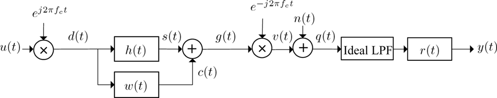
The block diagram in Figure 1 illustrates our simplified model of a practical radar system and its essential features. In the model, u(t) is a complex-valued finite duration baseband transmit waveform for −T/2 ≤ t ≤ T/2, where T is the signal duration time. The scattering of target and clutter are viewed as linear processes that are modelled by the system impulse response h(t) and w(t) respectively, here h(t) is the impulse response of the extended target and is assumed to be deterministic and integrable and w(t) is a zero-mean complex wide sense stationary (WSS) Gaussian random process with known power spectral density (PSD) Pww(f). The transmit signal u(t) is modulated to the transmission carrier frequency fc and passes through the target channel h(t) and clutter random channel w(t), the return echo is demodulated to baseband signal v(t) and then passes the ideal low-pass filter (LPF) with passband [−B/2, B/2]. In addition, n(t) is the zero-mean additive WSS Gaussian noise with known PSD Pnn(f) and is supposed to be independent of u(t), h(t) and w(t). Because the impulse response h(t) and w(t) are assumed to be independent in practical applications, the target echo s(t) and the clutter returns c(t) are also independent when the transmitted signal u(t) is deterministic and accurately known.
From the system model in Figure 1, we obtain that the output signal y(t) is:
3. SCNR-Based Waveform Design in Clutter
Referring to the previous modeling assumptions and formulations, the receiver output SCNR at time t0 is defined as:
Then, our objective is to jointly optimize the transmit waveform u(t) and the receiver-filter r(t) for maximizing SCNRt0 defined in (4). Let S(f), C(f) and V(f) be the Fourier transforms of s(t), c(t) and v(t) respectively; the energy of target echo, clutter and noise are:
Considering the imposed constraints of finite energy and duration time on the transmit waveform given in Equations (2) and (3), the Lagrangian multiplier technique can be applied to obtain the maximization of SCNR in Equation (11). The objective function is constituted as:
Let the first derivative of Equation (13) with respect to the signal ESD |U(f)|2 equal zero to obtain that:
Considering the nonnegativity of ESD, the optimal ESD of transmit waveform that can maximize output SCNR is that:
From the above analysis, the optimal ESD of complex-valued transmit waveform that maximizes the output SCNR at the receiver can be illustrated by the “water-filling” model [26]. This similar result is also described in [15,27].
4. Phase-Modulated Waveform Design
So far in this paper, an analytical solution for extended target detection is derived from SCNR constraints; under this condition, the time-domain signal can be synthesized by using finite impulse response filter design techniques and Durbin’s method as described in [28]. However, the synthetic signal that contains amplitude modulation cannot fully exploit the power of a transmitter in the practical radar system, the constraint of maximum waveform modulus is more suitable for the practical implementation [16]. Based on these considerations, a phase-iterative algorithm is proposed for use in designing an appropriate phase-modulated waveform that can approximate the optimal ESD in the mean-square sense.
We now consider the problem of finding waveforms with constant envelope that approximate the optimal ESD. We assume that upm(t) is a complex-valued phase-modulated waveform given by:
Our problem can be further stated as “find the appropriate signal upm(t) that can make the output SCNR difference between the optimal transmit waveform and phase-modulated waveform as small as possible”, which is defined by:
Our next objective is to minimize the ESD difference G(ϕ(t)) within the passband [–B/2, B/2]. In Appendix A, we derive that the approximation in Equation (20) can promise a small output SCNR difference, which can be described by:
Because most of the radar systems are digitized, and for the convenience of simulation, we use a discrete-time formulation to replace the representation of signal in Equation (20). We assume that Ts is the sampling interval, then the signal in discrete time is defined as:
Because it is difficult to conjointly solve the phase vector ϕ, we can optimize the elements of phase vector ϕ one by one. This method of updating ϕ can also keep the ESD difference G(ϕ) decreasing monotonically with each iterative step. In Appendix B, we find that the appropriate phase element ϕk that satisfies ∂G(ϕ)/∂ϕk = 0 and can minimize G(ϕ), where ∂G(ϕ)/∂ϕk is the first-order partial derivative of G(ϕ) with respect to phase ϕk, which indicates the phase of upm(t) at the kth sampling time, and is the second-order partial derivative. Therefore, the elements of phase vector ϕ from ϕ0 to ϕN–1 can be sequentially adjusted.
The phase-iterative algorithm for phase-modulated waveform design can be summarized as follows:
Initialize the phase vector ϕ, e.g., ϕ(0) = [0, ⋯, 0]T.
Let the initial number be p = 0 and calculate the ESD difference G(0).
p = p + 1.
Set k from 0 to N – 1 and find the solution of the equation by using Appendix B as a guide, which satisfies .
The updated signal is u(p) = cejϕ(p), G(p) = G(ϕ(p)) and δ = G(p) – G(p−1).
If δ > D, where D is a predefined threshold, go to step (3); otherwise, u(p) is the solution.
Since G (ϕ) decreases monotonically with each iterative step, the phase-modulated waveform ESD ɛpm(f) can approximate the optimal transmit ESD ɛopt(f) as much as possible in the mean-square sense.
5. Simulations and Discussions
In this section, numerical results are presented and some discussions are conducted to evaluate the performance of the optimal waveform design for extended target detection and the proposed phase-iterative algorithm for the phase-modulated waveform design.
5.1. Optimal ESD of Transmit Waveform Design
5.1.1. A Numerical Example
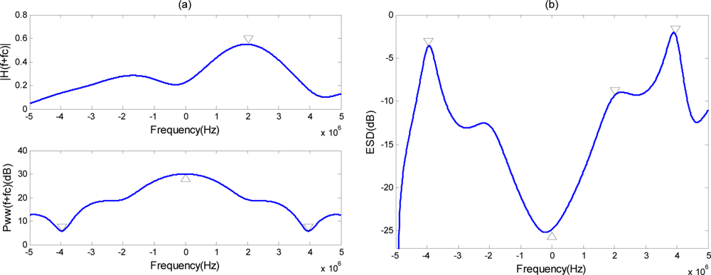
We now consider the following scenario. The carrier frequency fc is 10 GHz, the bandwidth B is 10 MHz, the energy of transmit signal E is 106 joules, and the additive noise is white with PSD Pnn(f) = 1 for f ∈ [−B/2, B/2]. A target with multiple reflection centers according to the multiple reflection model [30] is adopted here, the impulse response h(t) of which can be denoted as , the number of reflection centers K is 15. The reflection coefficients hi are assumed to follow a zero-mean Gaussian distribution with unit variance. The different delays ti are the independent samples following a uniform distribution between 0 and 0.33 μs, which means that the range span of the target is 50 m. The upper subfigure of Figure 2(a) shows the amplitude spectrum of an extended target; the lower subfigure shows the PSD of the clutter random channel. The optimal ESD of transmit waveform is shown in Figure 2(b). As expected, the optimal transmit ESD for extended target detection places as much energy as possible into the mode of the extended target that gives the largest response when weighted with the clutter. This demonstrates that the waveform design for optimal target detection de-emphasizes the frequency bands where clutter is significant and emphasizes the frequency bands where the target response is significant.
5.1.2. Point Target Assumption
Under this assumption, the impulse response of a point target can be represented by a delta function; therefore, the amplitude spectrum of the target impulse response will be a specified value A for the passband [−B/2, B/2]. The optimal transmit ESD for extended target detection in Equation (15) is in accordance with that for point target detection, and the optimal ESD of signal is:
For the transmit energy constraint in Equation (3) to hold, we have:
As we can see from Equation (27), |U(f)|2 = ξ/Pww(f + fc), where ξ is a constant. The PSD of clutter returns c(t) will be Pcc(f + fc) = |U(f)|2 Pww(f + fc) = ξ, it means the optimal signal can whiten the clutter. This result is the same as Kay’s given in [9].
5.2. Phase-modulated Waveform Design
5.2.1. A Numerical Example and Statistical Results
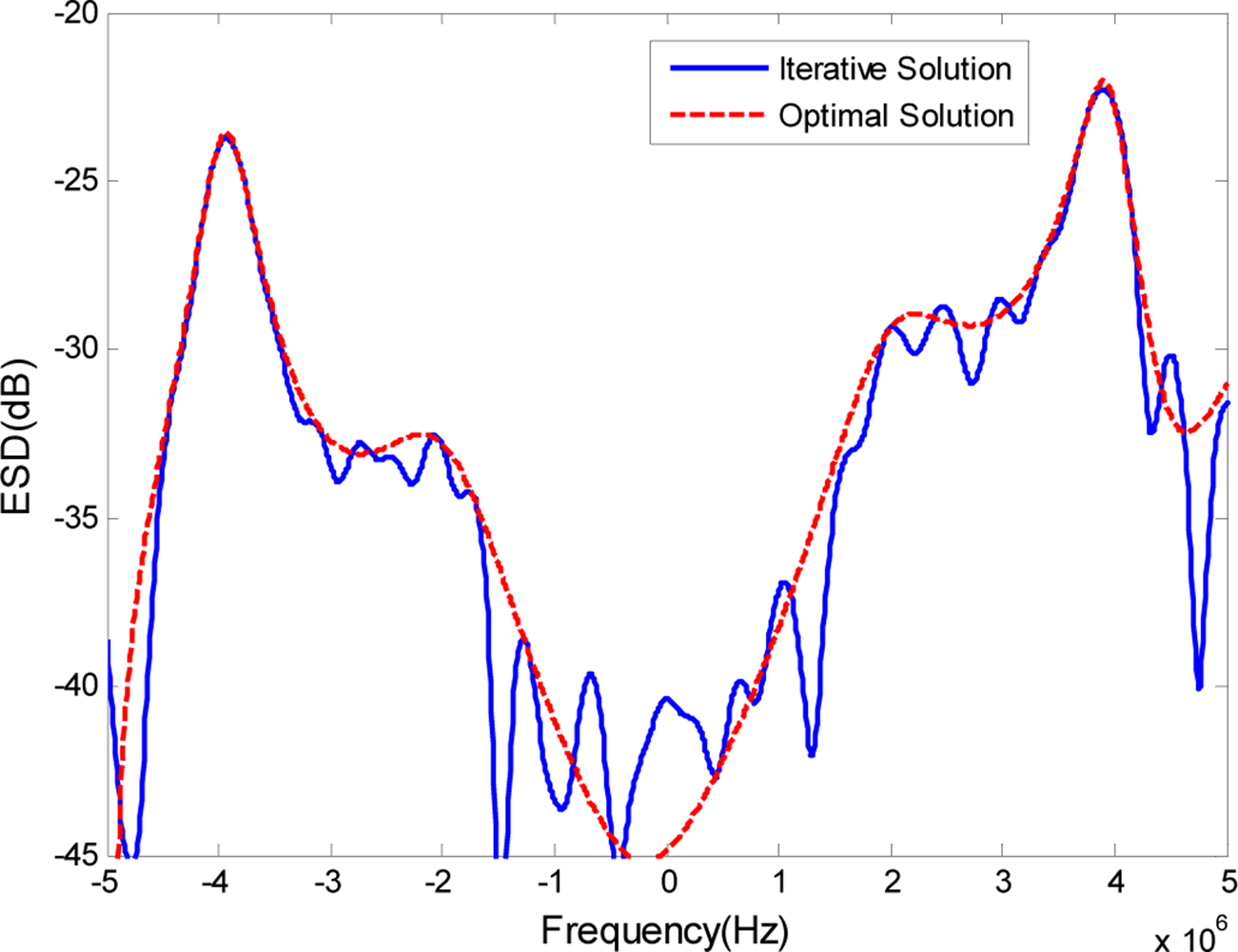
We now consider an example to illustrate the proposed method for designing the phase-modulated waveform and examine the characteristics of the designed waveform. The signal duration time T is 3 μs, and the sampling interval Ts is 1/(20B). The optimal transmit ESD shown in Figure 2(b) is employed as the approximated ESD. For convenience, the optimal transmit waveform is normalized to ‖Uopt(f)‖ = 1, here ‖·‖ is the 2-norm operator.
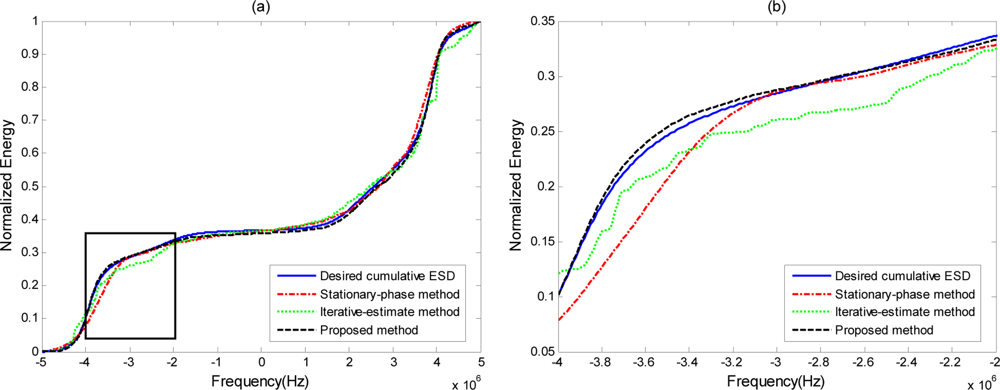
The optimal transmit ESD when the cut-off threshold D is 10−5 is shown in Figure 3 as a short dashed curve, along with the ESD of the phase-modulated waveform, which is shown as a solid curve. It is expected that the ESD of the phase-modulated waveform designed by our approach will appear very similar to the optimal transmit ESD. The output SCNR under the phase-modulated signal SCNRpm is 28.35 dB, while the maximal receiver output SCNR under the optimal transmit waveform SCNRmax is 28.83 dB. The level of similarity between the ESD of the designed phase-modulated waveform using the proposed method and the optimal ESD can be visualized better by the normalized cumulative ESDs in Figure 4. At the same time, it can be compared against the cumulative ESD of the signal synthesized using the stationary-phase method [21] and the iterative-estimate method [23]. Normalized cumulative ESD is defined as:
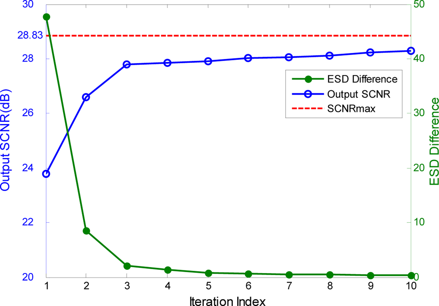
The zoomed version of the section highlighted in a box in Figure 4(a) is shown in Figure 4(b). As we can see, the stationary—phase and iterative-estimate methods deviate from the desired cumulative ESD around the edges, while the proposed method follows the desired cumulative ESD very closely. This means that the proposed method outperforms the stationary-phase and iterative-estimate methods when the desired ESD has many sudden fluctuations. Figure 5 shows the variation of the output SCNR (the left longitudinal axis of the coordinates) and the ESD difference G(ϕ) (the right longitudinal axis of coordinates) over 10 iterative steps using the proposed method. We can see that with decreasing G(ϕ) the corresponding output SCNR under the designed phase-modulated signal, shown by the dashed curve, converges to the maximal SCNR and that it achieves 0.53 dB difference at the 10th iteration. From the above results, it can be concluded that the phase-modulated waveform designed by our proposed phase-iterative algorithm can achieve satisfactory output SCNR approximation to the maximal output SCNR.
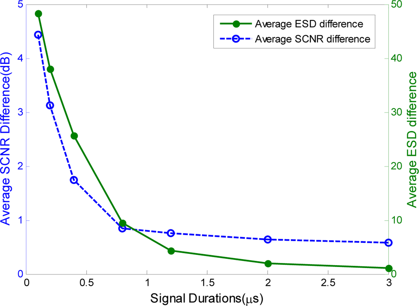
In additional, we performed Monte Carlo simulations to characterize the performance of our proposed phase-iterative algorithm. Figure 6 shows the results of a Monte Carlo simulation with 1000 target samples generated according to the multiple reflection model [30] and 1,000 samples of the clutter power spectrum [31]. The average ESD difference and SCNR difference are used to evaluate the performance of the proposed method. As shown in Figure 6, the average SCNR difference decreases and converges to zero with increased signal duration because the monotonically-decreasing ESD difference G(ϕ) is much smaller with the longer signal duration.
5.2.2. Initialization of Phase-iterative Algorithm
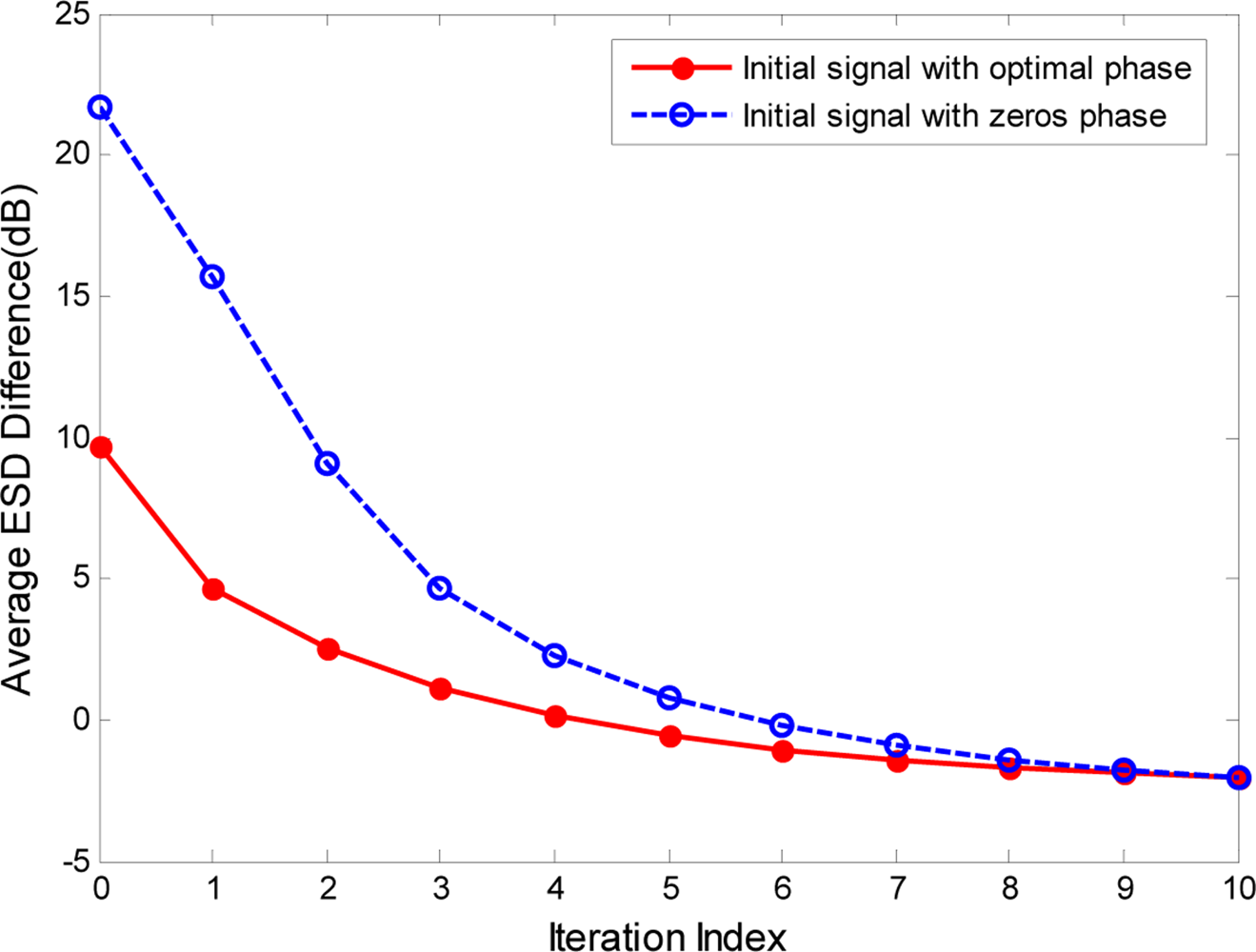
The initialization of the phase vector ϕ in the proposed phase-iterative algorithm is a considerable problem that can affect the convergence of the iterative solutions. In our approach, the phase vector ϕ of the phase-modulated signal upm(t) is always initialized to zeros and will be adjusted within the iterations to reduce the ESD difference G(ϕ). Because the phase term of upm(t) contains the spectrum characteristics of Upm(f), the phase vector ϕ can also be initialized to the angle of optimal signal uopt(t), which is the inverse Fourier transform of the optimal transmit spectrum Uopt(f). In this way, more energy of Upm(f) can be concentrated at a frequency band in which the optimal ESD ɛopt(f) is much larger. However, from the definition of ESD, the phase term of uopt(t) can not be directly obtained from the optimal ESD ɛopt(f). We therefore assume that the phase of the optimal spectrum Uopt(f) is represented by an independent sampling of a uniform distribution on [−π, π]. Figure 7 shows the results of a Monte Carlo simulation with 1,000 target samples and clutter power spectrum samples when the signal duration T is assumed to be 2 μs. As seen in Figure 7, the phase initialization of signal upm(t) by the optimal phase, which is the angle of the optimal signal uopt(t), can achieve a better ESD approximation with fewer iterations.
6. Conclusions
The problem of detecting targets in clutter has been the subject of much research and has led to the development of clutter rejecting waveforms. In this paper, we perform the phase-modulated waveform design for approximating to the optimum performance of the extended target detection. A simple theoretical solution of the optimal ESD of complex-valued transmit waveform is obtained. Based on this, we present a novel phase-iterative method for designing the phase-modulated waveform, aiming to minimize the mean-square spectral distance between the optimal waveform and the designed waveform, which can promise the approximation of the output SCNR to the maximum SCNR. The numerical simulations show that the advantage of the proposed phase-iterative waveform design technique is substantial, and that our approach outperforms the stationary phase method and other phase-modulated waveform design methods.
Acknowledgments
This work was supported in part by the National Natural Science Foundation of China (No. 60901057).
Appendix A
As described in Section 4, we assume that ɛopt(f) is the optimal ESD of the transmit waveform uopt(t) and that ɛpm(f) is the ESD of the phase-modulated waveform upm(t). The objective function to be minimized is:
From the results in Section 3, the maximum receiver output SCNR is given by:
Therefore, when the transmit waveform is a phase-modulated signal upm(t), the output SCNR is calculated by:
For simplicity, let Pww(f + fc) = c(f), |H(f + fc)|2 = h(f), and Pnn(f) = n(f). The SCNR difference is defined as:
Applying the Cauchy–Schwarz inequality to equation (33), we have that:
According to the previous assumptions in Section 2, the spectrum of extended target impulse response H(f + fc) and the noise PSD Pnn(f) are both supposed to be deterministic and to be known, K̃′ can be viewed as a constant, we have:
Appendix B
From the definition of ESD difference G(ϕ) in (24), the partial derivative of G(ϕ) with respect to ϕk which indicates the phase of upm(t) at the kth sampling time, is:
Therefore, the appropriate phase element ϕk that minimizes G(ϕ) must satisfy ∂G(ϕ)/∂ϕk = 0 and . We let , and x = ejϕk, so the first derivative is:
It is clear that for ∂G(ϕ)/∂ϕk = 0, we must have:
Because G(ϕ) is real and periodic with the period equal to 2π, the extreme points are present in pairs within the analysis interval. Thus, the solutions of Equation (44) must exit and be conjugated in the analysis interval. Besides, the coefficients of Equation (44) that are conjugated in pairs make the solutions be unity amplitude and be easily solved by a general quartic equation solving method. Furthermore, we must obtain the appropriate solution xo, which can make:
References
- Van Trees, H. Detection, Estimation, and Modulation Theory, Part I; Wiley; New York, NY, USA, 1968. [Google Scholar]
- Rummler, WD. Clutter suppression by complex weighting of coherent pulse trains. IEEE Trans. Aerosp. Electron. Syst. 1966, 2, 689–699. [Google Scholar]
- Thompson, JS; Titlebaum, EL. The design of optimal radar waveforms for clutter rejection using the maximum principle. IEEE Trans. Aerosp. Electron. Syst. 1966, 3, 689–699. [Google Scholar]
- Delong, DF; Hofstetter, EM. On the design of optimum radar waveforms for clutter rejection. IEEE Trans. Inf. Theory 1967, 13, 454–463. [Google Scholar]
- Yazici, B; Xie, G. Wideband extended range-doppler imaging and waveform design in presence of clutter and noise. IEEE Trans. Inf. Theory 2006, 52, 4563–4580. [Google Scholar]
- Bell, MR. Information theory and radar waveform design. IEEE Trans. Inf. Theory 1993, 39, 1578–1597. [Google Scholar]
- Goodman, NA; Venkata, PR; Neifeld, MA. Adaptive waveform design and sequential hypothesis testing for target recognition with active sensors. IEEE J. Sel. Top. Signal Process 2007, 1, 105–113. [Google Scholar]
- Pillai, SU; Oh, HS; Youla, DC; Guerci, JR. Optimum transmit-receiver design in the presence of signal-dependent interference and channel Noise. IEEE Trans. Inf. Theory 2000, 46, 577–584. [Google Scholar]
- Kay, S. Optimal signal design for detection of gaussian point targets in stationary gaussian clutter/reverberation. IEEE J. Sel Top. Signal Process. 2007, 1, 577–584. [Google Scholar]
- Kay, S. Waveform design for multistatic radar detection. IEEE Trans. Aerosp. Electron. Syst. 2009, 45, 1153–1166. [Google Scholar]
- Guo, D; Shamai, S; Verdu, S. Mutual information and minimum mean-square error in Gaussian channels. IEEE Trans. Inf. Theory 2005, 51, 1261–1282. [Google Scholar]
- Yang, Y; Blum, RS. MIMO radar waveform design based on mutual information and minimum mean-square error estimation. IEEE Trans. Aerosp. Electron. Syst. 2007, 43, 330–343. [Google Scholar]
- Naghibi, T; Namvar, M; Behnia, F. Optimal and robust waveform design for MIMO radars in the presence of clutter. Signal Process. 2010, 90, 1103–1117. [Google Scholar]
- Leshem, A; Naparstek, O; Nehorai, A. Information theoretic adaptive radar waveform design for multiple extended targets. IEEE J. Sel. Top. Signal Process. 2007, 1, 42–55. [Google Scholar]
- Romero, R; Bae, J; Goodman, NA. Theory and application of snr and mutual information matched illumination waveforms. IEEE Trans. Aerosp. Electron. Syst. 2011, 47, 912–927. [Google Scholar]
- Patton, LK; Rigling, BD. Modulus Constraints in Adaptive Radar Waveform Design. Proceedings of the 2008 IEEE Radar Conference, Rome, Italy, May 2008; pp. 1–6.
- Li, J; Guerci, JR; Xu, LX. Signal waveform’s optimal-under-restriction design for active sensing. IEEE Signal Process. Lett. 2006, 13, 565–568. [Google Scholar]
- Zhang, J; Zhu, X; Wang, H. Adaptive radar phase-coded waveform design. IET Electron. Lett. 2009, 45, 1052–1053. [Google Scholar]
- Wei, YM; Meng, HD; Wang, XQ. Adaptive Single-Tone Waveform Design for Target Recognition in Cognitive Radar. Proceedings of the 2009 IET International Radar Conference, Guilin, China, April 2009; pp. 707–710.
- Jiu, B; Liu, HW; Li, LY; Wu, SJ. Waveform design for broadband radar based on phase modulated signal. J. Electron. Inf. Technol. 2008, 30, 2038–2041. [Google Scholar]
- Key, EL; Fowle, EN; Haggarty, RD. A method of designing signals of large timebandwidth product. IRE Int. Conv. Rec. 1961, 4, 146–154. [Google Scholar]
- Zhang, LP. An Optimization method for a kind of nlfm pulse compression waveform. Mod. Radar 1994, 5, 27–34. [Google Scholar]
- Jackson, L; Kay, S; Vankayalapati, N. Iterative method for nonlinear fm synthesis of radar signals. IEEE Trans. Aerosp. Electron. Syst. 2010, 46, 910–917. [Google Scholar]
- Stoica, P; Hao, H; Jian, L. New algorithms for designing unimodular sequences with good correlation properties. IEEE Trans. Signal Process. 2009, 57, 1415–1425. [Google Scholar]
- Jacobs, SP; OSullivan, JA. Automatic target recognition using sequences of high resolution radar range profiles. IEEE Trans. Aerosp. Electron. Syst. 2000, 36, 364–381. [Google Scholar]
- Gallagher, RB. Information Theory and Reliable Communication; Wiley: New York, NY, USA, 2002. [Google Scholar]
- Mao, T; Gong, XH; Meng, HD; Wang, XQ. Phase-Modulated Waveform Design for the Target Detection in the Presence of Signal-Dependent Clutter. Proceedings of the 2010 Waveform Diversity and Design Conference, Niagara Falls, ON, Canada, 8–13 August 2010; pp. 100–104.
- Kay, S. Fundamentals of Statistical Signal Processing: Estimation Theory; Prentice-Hall: Upper Saddle River, NJ, USA, 1993. [Google Scholar]
- Jackson, LB. Digital Filters and Signal Processing; Springer: New York, NY, USA, 1995. [Google Scholar]
- Van Trees, H. Detection, Estimation and Modulation Theory, Part III: Radar and Sonar Signal Processing; Wiley: New York, NY, USA, 2002. [Google Scholar]
- Richards, M. Fundamentals of Radar Signal Processing; McGraw-Hill: New York, NY, USA, 2005. [Google Scholar]


© 2011 by the authors; licensee MDPI, Basel, Switzerland. This article is an open access article distributed under the terms and conditions of the Creative Commons Attribution license (http://creativecommons.org/licenses/by/3.0/).
Share and Cite
Gong, X.; Meng, H.; Wei, Y.; Wang, X. Phase-Modulated Waveform Design for Extended Target Detection in the Presence of Clutter. Sensors 2011, 11, 7162-7177. https://doi.org/10.3390/s110707162
Gong X, Meng H, Wei Y, Wang X. Phase-Modulated Waveform Design for Extended Target Detection in the Presence of Clutter. Sensors. 2011; 11(7):7162-7177. https://doi.org/10.3390/s110707162
Chicago/Turabian StyleGong, Xuhua, Huadong Meng, Yimin Wei, and Xiqin Wang. 2011. "Phase-Modulated Waveform Design for Extended Target Detection in the Presence of Clutter" Sensors 11, no. 7: 7162-7177. https://doi.org/10.3390/s110707162
APA StyleGong, X., Meng, H., Wei, Y., & Wang, X. (2011). Phase-Modulated Waveform Design for Extended Target Detection in the Presence of Clutter. Sensors, 11(7), 7162-7177. https://doi.org/10.3390/s110707162