Article

Enhanced NiFe2O4 Catalyst Performance and Stability in Anion Exchange Membrane Water Electrolysis: Influence of Iron Content and Membrane Selection

Department of Chemical Engineering, University of Waterloo, Waterloo, ON N2L 3G1, Canada
*
Authors to whom correspondence should be addressed.
Molecules 2025, 30(15), 3228; https://doi.org/10.3390/molecules30153228 (registering DOI)
Submission received: 25 June 2025 / Revised: 17 July 2025 / Accepted: 29 July 2025 / Published: 1 August 2025
(This article belongs to the Special Issue Water Electrolysis)

Abstract

Anion exchange membrane (AEM) water electrolysis is a potentially inexpensive and efficient source of hydrogen production as it uses effective low-cost catalysts. The catalytic activity and performance of nickel iron oxide (NiFeOx) catalysts for hydrogen production in AEM water electrolyzers were investigated. The NiFeOx catalysts were synthesized with various iron content weight percentages, and at the stoichiometric ratio for nickel ferrite (NiFe2O4). The catalytic activity of NiFeOx catalyst was evaluated by linear sweep voltammetry (LSV) and chronoamperometry for the oxygen evolution reaction (OER). NiFe2O4 showed the highest activity for the OER in a three-electrode system, with 320 mA cm−2 at 2 V in 1 M KOH solution. NiFe2O4 displayed strong stability over a 600 h period at 50 mA cm−2 in a three-electrode setup, with a degradation rate of 15 μV/h. In single-cell electrolysis using a X-37 T membrane, at 2.2 V in 1 M KOH, the NiFe2O4 catalyst had the highest activity of 1100 mA cm−2 at 45 °C, which increased with the temperature to 1503 mA cm−2 at 55 °C. The performance of various membranes was examined, and the highest performance of the tested membranes was determined to be that of the Fumatech FAA-3-50 and FAS-50 membranes, implying that membrane performance is strongly correlated with membrane conductivity. The obtained Nyquist plots and equivalent circuit analysis were used to determine cell resistances. It was found that ohmic resistance decreases with an increase in temperature from 45 °C to 55 °C, implying the positive effect of temperature on AEM electrolysis. The FAA-3-50 and FAS-50 membranes were determined to have lower activation and ohmic resistances, indicative of higher conductivity and faster membrane charge transfer. NiFe2O4 in an AEM water electrolyzer displayed strong stability, with a voltage degradation rate of 0.833 mV/h over the 12 h durability test.
Keywords:
AEM; PEM; OER; EIS

1. Introduction

Several existing renewable energy sources have considerable limitations in terms of capacity, being highly conditional on specific conditions and influenced by uncontrollable factors such as the availability of sunlight and wind speeds [1]. Therefore, many such sources are unable to keep up with peak power requirements and produce excess power during low usage times. In this context, hydrogen shows considerable promise in acting as both a fuel and a storage medium for these other renewable energy sources. Hydrogen has a very high specific energy density by mass, and can produce three times as much energy as gasoline [2,3]. Furthermore, it is versatile in utilization, produces no pollutants during use, and as a gas is relatively cheap to transport [4].
There are several methods currently employed to generate hydrogen including water electrolysis, gasification, fermentation, steam reforming, photocatalytic, and water thermolysis [5]. Water electrolysis shows considerable potential for sustainable hydrogen generation among the mentioned methods. While it is more expensive and less utilized than other methods such as steam reforming, it produces no pollutants or environmentally harmful byproducts. Specifically, electrolysis based on renewable sources, such as hydroelectric or wind energy, produces at least three times less CO2 per kg of H2 when compared to steam reforming [6,7].
There are three primary methods of water electrolysis: alkaline water electrolysis (AWE), proton exchange membrane (PEM) water electrolysis, and anion exchange membrane (AEM) water electrolysis. Currently, only AWE is widespread on an industrial scale, which can primarily be attributed to the low cost of AWE systems. However, despite being the most frequently used, AWE shows several limitations such as low current densities and comparatively lower purity and pressure compared to PEM and AEM systems [8,9]. PEM systems show better performance and purity; however, the high costs associated with the development and operation of PEM electrolyzers present significant barriers, making their widespread adoption challenging. PEM water electrolyzers require expensive structural materials due to the acidic operational environment, generally consisting of titanium or other noble metals in the gas diffusion mesh and bipolar plates. Furthermore, for the same reason, noble metal catalysts are required. The scarcity of the materials used results in high operational costs that often render PEM water electrolyzers uneconomical [10,11].
AEM electrolyzers have been receiving considerable attention and have been the focus of developmental efforts due to their innate advantages over AWE and PEM systems. AEM systems utilize an anion exchange membrane (AEM) and operate in a basic solution of 0.1–1 M KOH or NaOH [12]. Operation in water is possible; however, it results in lower performance as the electrolytes in the solution increase conductivity and reduce the corrosion of the catalyst [13]. The alkaline environment allows for non-noble metal catalysts, such as transition metal oxides, as well as removing the structural material requirements found in PEM systems. This allows AEM electrolyzers to use more common and cheaper materials, typically substituting platinum group materials (PGMs) for nickel-based materials [14]. These fundamental differences allow for reduced costs when compared to PEM water electrolyzers, while displaying greater performance compared to AWE systems [15,16].
Despite their advantages over AWE and PEM systems, there are still several key challenges in utilizing AEM electrolyzers for hydrogen generation. AEM electrolyzers, despite their lower cost, show lower current density and energy efficiency when compared to PEM water electrolyzers [17]. These deficiencies can be largely attributed to high overpotentials found in oxygen evolution reaction (OER) catalysts. As such, one primary focus for development in AEM systems is the development of low overpotential catalysts. Noble metal oxides have been found to be effective for this purpose. However, they are scarce and expensive to use. Perovskite- and Chalcogenide-based catalysts with bifunctional catalytic activity for the OER and HER have also been an area of research in the non-PGM catalyst search [18,19,20]. A chemically bifunctional catalyst, LaCoO3-MoS2, has been shown as a noble-metal-free electrocatalyst for alkaline water splitting, achieving efficient hydrogen evolution reaction (HER) and OER performance [21]. Spinel-structured first-row transition metal oxides have received the most attention due to their efficiency as electrocatalysts and their relative abundance [22,23,24]. NiFe2O4-based catalysts show promise and potential for this application. One reason is due to the polyvalent redox pairs present (Ni2+/Ni3+ and Fe2+/Fe3+), which can act as redox active sites for oxygen evolution [25]. Additionally, they possess high stability as well as corrosion resistance, which helps mediate a major concern in the long-term operation of AEM electrolyzers [22]. Furthermore, they are abundant and high in reserve, resulting in low costs, especially when compared to noble metal-based catalysts [25].
NiFe2O4-based catalysts have shown high performance in the literature for OER and AEM applications. NiFe2O4 nanoparticles, sized at 10 nm, showed high activity in the OER, achieving a current density of 10 mA cm−2 at an overpotential of 290 mV, with a Tafel slope of 42 mV dec−1 [22]. Furthermore, NiFe2O4 nanorods have also shown excellent performance, with mesoporous NiFe2O4 nanorod catalysts reaching 10 mA cm−2 at an overpotential of 342 mV, with a Tafel slope of 44 mV dec−1 [23]. Furthermore, doping or mixing NiFe2O4 with various materials has shown an increase in performance. NiO/NiFe2O4 biphasic nanorods achieve 10 mA cm−2 at a reduced overpotential of 302 mV, with a slightly lower Tafel slope of 42 mV dec−1, and an increased specific surface area when compared to standard NiFe2O4 nanorods [24]. A NiFe2O4@Co3O4 heterostructure catalyst achieved 10 mA cm−2 at an overpotential of 251 mV with a low Tafel slope of 36 mV dec−1 [26]. The electrocatalytic performance of pentlandite-like FexNi9−xS8 nanoparticles for the oxygen evolution reaction has been systematically studied, demonstrating improved activity with increasing nickel content [27]. For AEM water electrolysis, NiFe2O4 catalysts have been studied and reported to have good activity.
In this study, NiFeOx and NiFe2O4 catalysts were synthesized; in NiFeOx catalysts, the Fe content was changed from 5 to 12.5 wt% of total metal content. The OER was performed in three-electrode systems, and complete water electrolysis was performed using an AEM electrolyzer. Electrochemical impedance spectroscopy (EIS) was performed to evaluate different resistances due to the electrolyzer components. Long-term and short-term durability testing was also performed using NiFe2O4 at the anode. In addition, several anion exchange membranes (AEMs) were tested, and their performance was compared for AEM water electrolysis.

2. Results

SEM and EDS analyses were carried out using the Leo 1550 SEM (Zeiss, Dublin, CA USA). Figure 1a shows the morphology of the nickel foam anode GDL. Nickel foam had a pore size in the range of 100 to 500 μm, which provides easier access to water and oxygen at the anode to transport. The cross-sectional image shows the total width of the catalyst-coated nickel foam, which had a thickness of 740 μm, as shown in Figure 1b. The NiFe2O4 catalyst layer was dense, and catalyst particles were distributed within the matrix of the nickel foam. Figure S1 in the Supplementary Material shows the schematic of the membrane electrode assembly, where nickel foam was used as a gas diffusion layer at the anode, and the NiFeOx or NiFe2O4 catalyst layer was used on top of it, while at the cathode side, a carbon paper GDL was used with a Pt/C catalyst. Figure 1c shows the EDS of NiFe2O4, which clearly shows the Ni-to-Fe ratio of approximately 1:2. The EDS results of other catalysts are presented in Figures S2–S4 in the Supplementary Material. In all cases, the catalyst composition was confirmed from the EDS analysis.
Catalysts were analyzed by XRD (Rigaku Miniflex 600, Tokyo, Japan) using Cu-Kα radiation (λ = 1.54184 Å).
NiFeOx samples with varying Fe concentrations of 5%, 7.5%, and 12.5% exhibit the NiO phase, characterized by five distinctive peaks at 2θ values of 37.36, 43.36, 63, 75.54, and 79.56. These peaks are assigned to the crystallographic planes (hkl) of (111), (200), (220), (311), and (222), respectively. The diffraction peaks have been matched and indexed to NiO using the JCPDS card number 78-0643, as depicted in Figure 2.
The NiFe2O4 catalyst showed the typical diffraction pattern of NiFe2O4, with the main peak centered at 2θ 18.6, 30.5, 35.5, 37.5, 43.6, 54.3, 57.5 and 63.2, which are assigned to (111), (220), (311), (222), (400), (422), (511), and (440), respectively. The XRD data includes dashed lines representing the JCPDS standard for NiFe2O4. The JCPDS card number 22-1086 was used to match the diffraction lines of NiFe2O4.

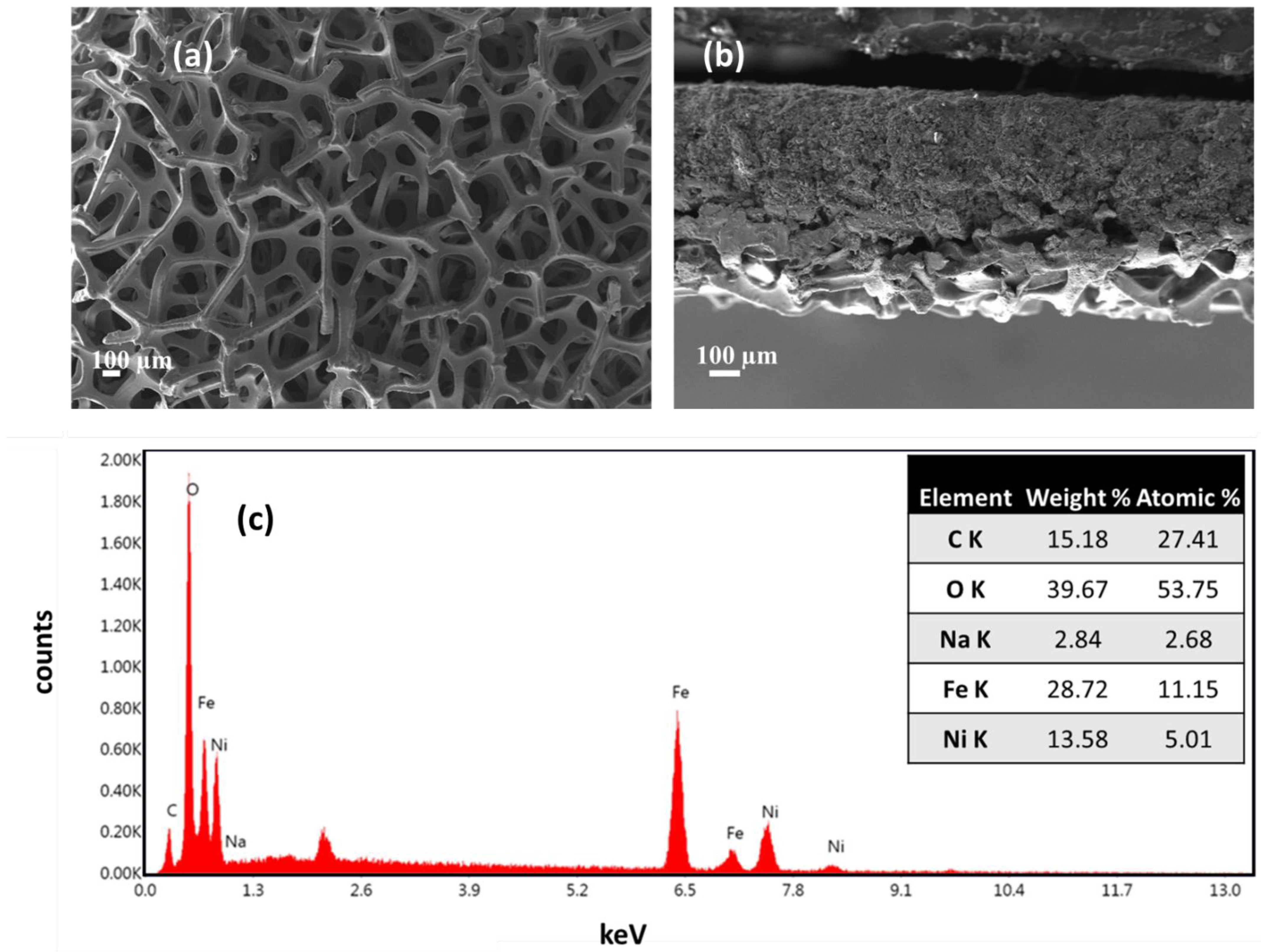
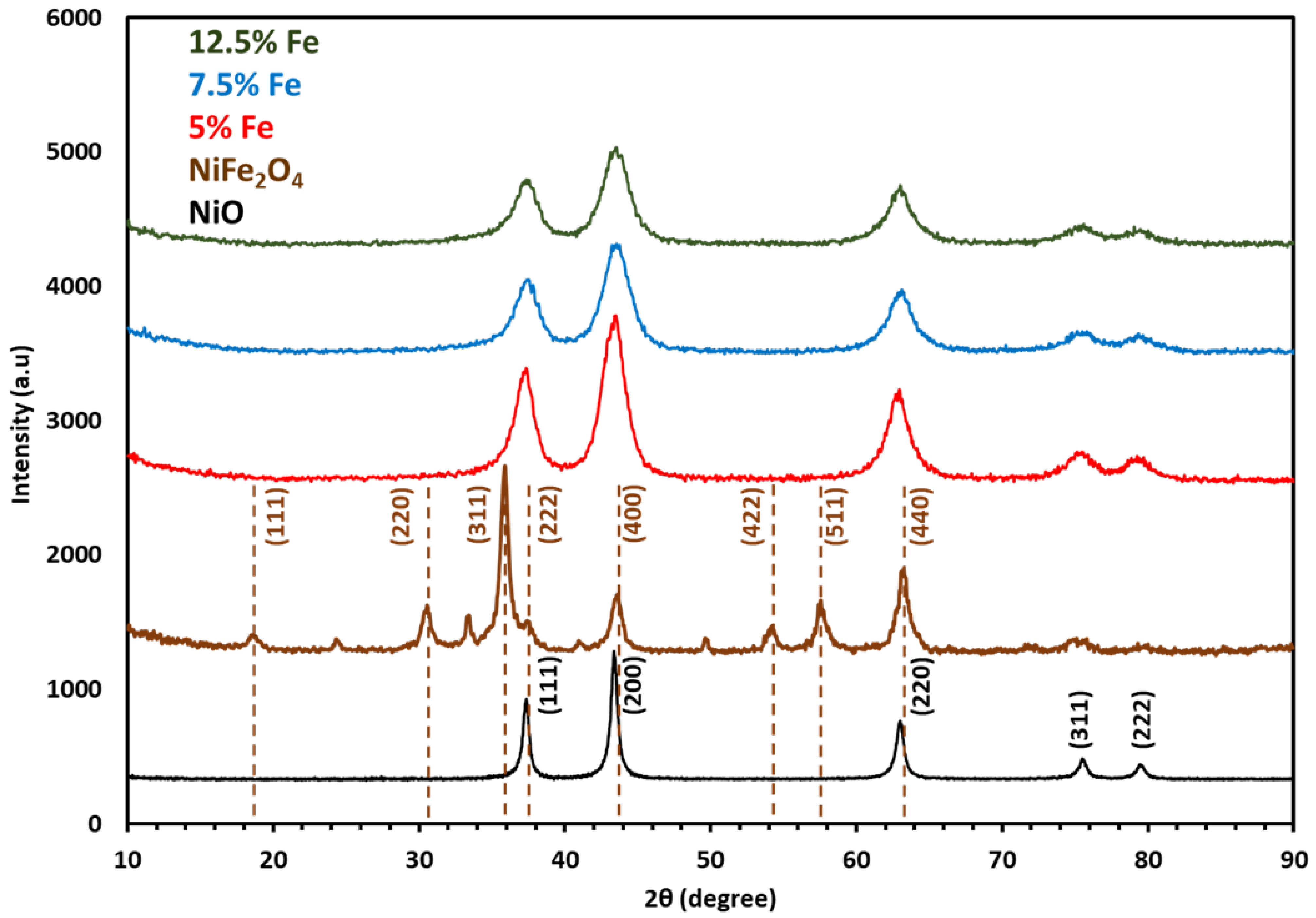
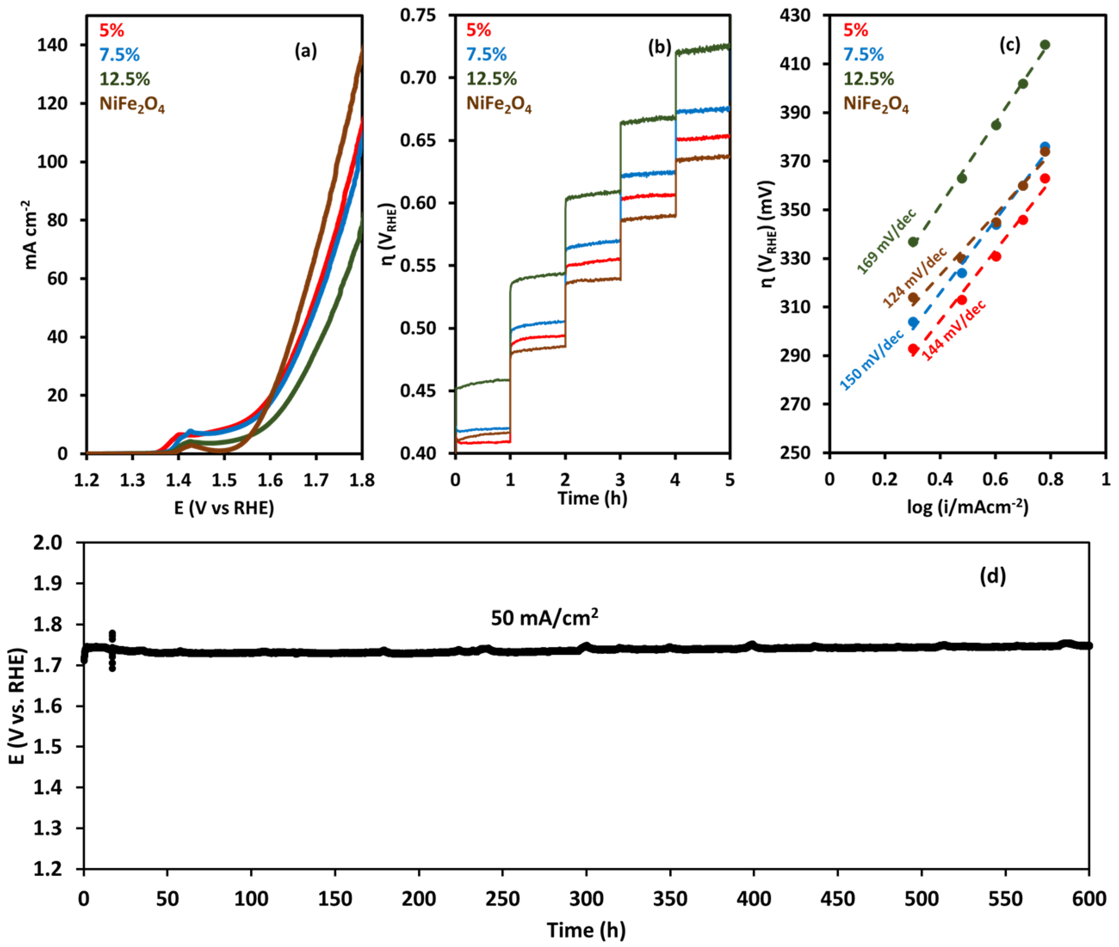
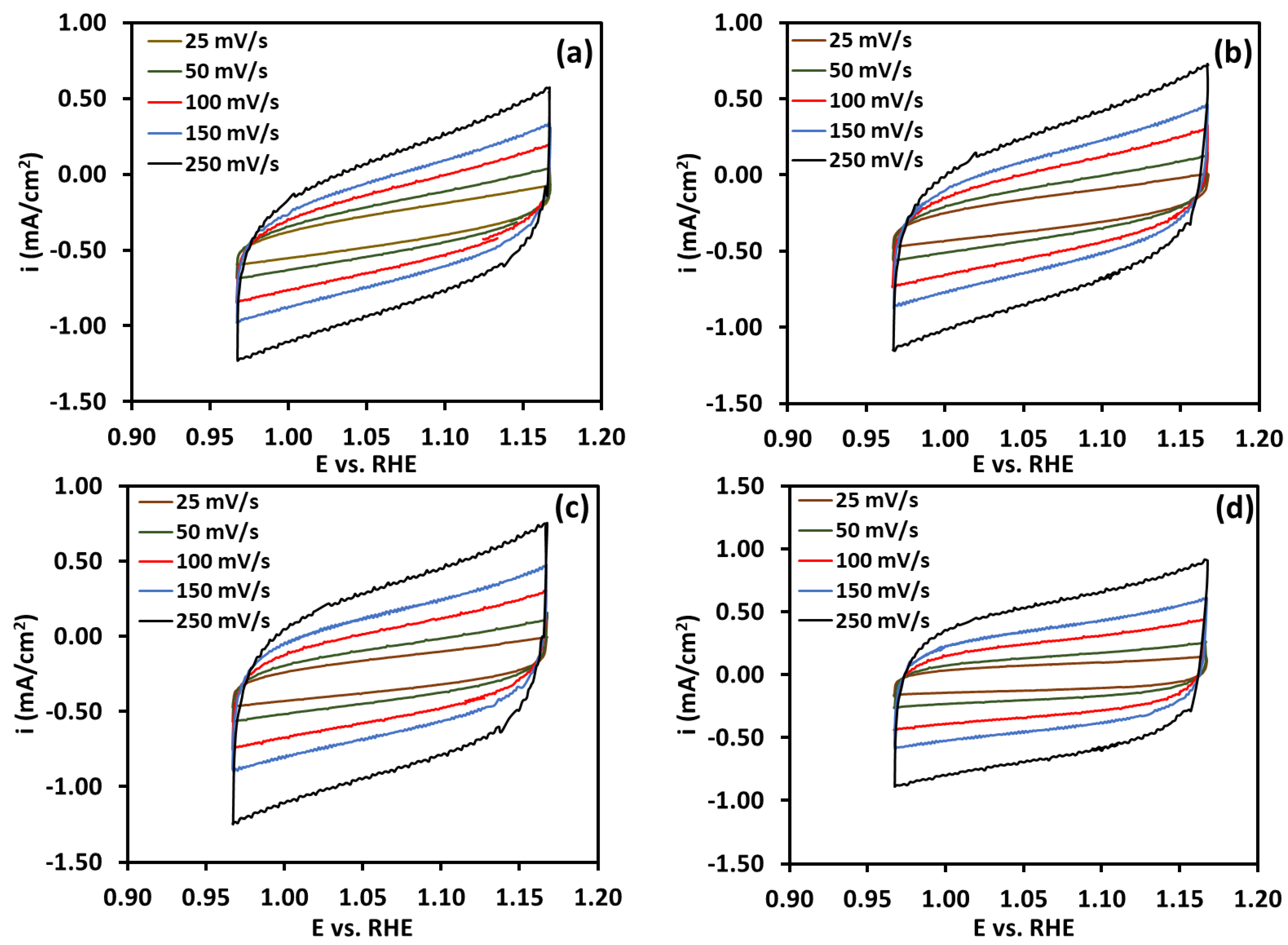
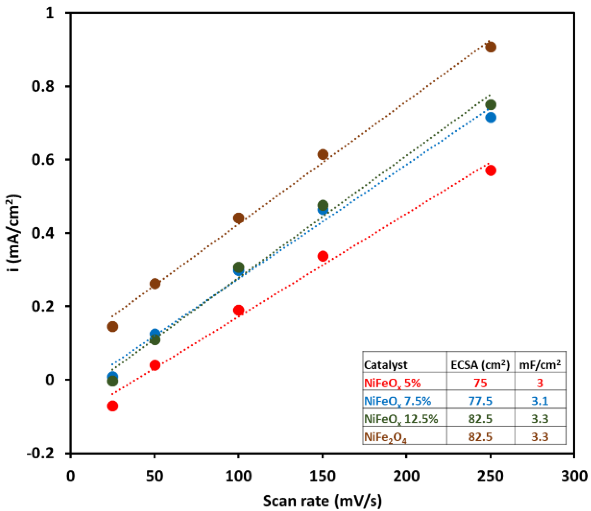
2.1. Oxygen Evolution Reaction

To evaluate the catalytic activity of the NiFeOx catalyst, linear sweep voltammetry was performed in 1 M KOH. NiFe2O4 showed the highest catalytic activity with a current density of 135 mA cm−2 at 1.8 V (Figure 3a). Figure 3b shows chronopotentiometry at current densities of 10 to 50 mA cm−2. At each voltage, the operation was performed for 1 h, which shows the short-term stability of the catalyst at these conditions. The lowest overpotential was 409 mV and 416 mV for the NiFeOx (5%) and NiFe2O4 catalysts, respectively. The highest overpotential was for NiFeOx (12.5%), which was 457 mV, followed by the overpotential of 419 mV for NiFeOx (7.5%). The catalyst performance was stable at a higher current density of 50 mA cm−2. These results show that the catalysts are stable under high-current-density operation and well suited for AEM electrolysis. Tafel plots, as depicted in Figure 3c, were used to compare the efficiency of different catalysts. These plots represent the correlation between overpotential η and current density (i) on a logarithmic scale. The Tafel slope (b), derived from the linear segment of the plot, is indicative of the catalyst’s activity. NiFe2O4 has a Tafel slope of 124 mV/dec and NiFeOx (12.5%) has a Tafel slope of 169 mV/dec. The Tafel slopes of NiFeOx (5%) and NiFeOx (7.5%) were 144 mV/dec and 150 mV/dec, respectively, which are in the same range. These results showed that the NiFe2O4 catalyst is a relatively more active catalyst among the series of catalysts. The value of the Tafel slope helps identify the rate-determining step (RDS) in the reaction mechanism. A Tafel slope of ~120 mV/dec typically indicates that the first electron transfer step (M + H2O → M–OH* + H+ + e) is the rate-determining step (RDS). A slope near 60 mV/dec suggests that a chemical step following an electron transfer (M–OH* → M–O* or M–O* + H2O → M–OOH* + H+ + e) is rate-limiting. A 30 mV/dec slope suggests that the surface coverage of intermediates is high, and the chemical recombination step (M–O → O2) is the RDS. In our case for all the catalysts, the Tafel slope is higher than 120 mV/dec, which shows that the adsorption of OH on the catalyst is the rate-determining step.
Figure S5 in Supplementary Information shows the EIS analysis at 1.7 V (vs. RHE) at 25 °C in 1 M KOH NiFe2O4 catalysts show a smaller semicircle compared to the other catalysts. The diameter of the semicircle in the Nyquist plot shows the activation resistance. This shows that the NiFe2O4 catalyst is more active in charge transfer with surface-adsorbed intermediates compared to other catalysts.
To test the activity and stability of NiFe2O4 catalysts for the OER, a durability test was performed for 600 h as shown in Figure 3d. The test was performed at a current density of 50 mA/cm2. The initial voltage was 1.739 V (vs. RHE), and during the 600 h operation, the voltage increased to 1.748 V. The degradation rate or the voltage increase rate was 15 μV/h during the 600 h OER test.
Figure 4a–d shows the CV plot; the scan rate ranged from 25 to 250 mV s−1, and the voltage ranged from 0.967 V to 1.167 V (non-Faradaic region for water electrolysis). Cdl, the double-layer capacitance, was calculated from the slope of the scan rate vs. current density plot in Figure 5. The electrochemical surface area (ECSA) was 75 cm2, 77.5 cm2, 82.5 cm2, and 82.5 cm2 for the NiFeOx (5% Fe), NiFeOx (7.5%), NiFeOx (12.5% Fe), and NiFe2O4 catalysts, respectively.

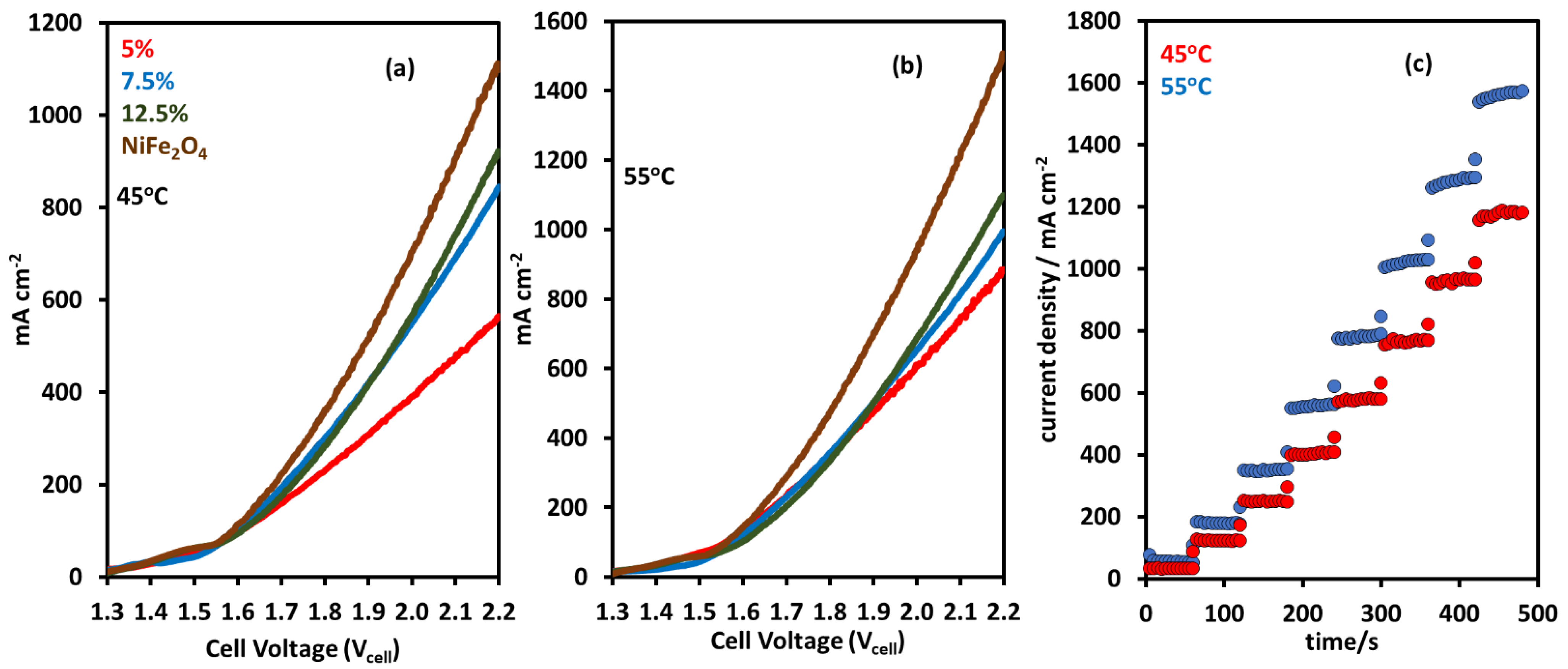
2.2. AEM Electrolyzer Tests with NiFeOx and NiFe2O4 Catalysts

Single-cell tests were performed with the NiFeOx catalyst at the anode and Pt/C at the cathode, using Ni foam and carbon paper GDLs, respectively, and a dioxide membrane (X-37-50 grade T). The AEM X-37-50 T from Sustainion® exhibits high conductivity and stability in AEM water electrolysis [28,29]. The membrane comprises co-polymers of styrene and vinyl benzyl chloride supported by polytetrafluoroethylene (PTFE), incorporating imidazolium and pyridinium groups for ion exchange. Figure 6a shows polarization curves using NiFe2O4 catalysts and NiFeOx catalysts at 45 °C. NiFe2O4 showed the highest activity of 1100 mA cm−2 at 2.2 V. Other catalysts also showed good activity for AEM electrolysis; at the same voltage, the catalyst with 12.5 wt% Fe had a current density of 921 mA cm−2. The current density decreased to 842 mA cm−2 and 561 mA cm−2 for catalysts with Fe contents of 7.5 wt% and 5 wt%. Figure 6b shows the polarization curves at 55 °C; for all the catalysts, the activity increased with the increase in temperature. The same trend emerges in the activity of the catalysts during the 45 °C electrolysis operation. NiFe2O4 shows the highest current density of 1503 mA cm−2, which is an increase of 36%. Current densities were 1098 mA cm−2, 994 mA cm−2, and 885 mA cm−2 for the catalysts with 12.5 wt%, 7.5 wt%, and 5 wt% Fe content.
Temperature is an important factor in the performance of an AEM electrolyzer, which must be considered during catalyst performance analysis. Increased temperature results in lower overpotentials for any given current density, as well as an increase in the efficiency of the electrolyzer [30,31,32]. The improved reaction kinetics play a large role in this, as the electrochemical reaction kinetics increase with temperature [33]. Furthermore, kinetics improve due to the reduced energy requirement for splitting water molecules, as there is additional energy present within the system. Increased ionic conductivity at higher temperatures also plays a large role in increasing performance due to the increase in mobility of OH ions, increasing their availability for the redox reaction [34].
The NiFe2O4 catalyst shows good activity for AEM water electrolysis in different operational conditions as reported in the literature. A current density of 1000 mA cm−2 was achieved at 1.85 V for AEM electrolysis using NiFe2O4 as the anode catalyst and Raney Nickel as the cathode catalyst in a 1 M KOH solution, with a Sustainion X-37-50 T membrane at 60 °C [35]. Additionally, a system using NiFe2O4 at the anode and 30 wt% PtNi/ECS (Engineered Catalyst Support, carbon) at the cathode had a current density of 1000 mA cm−2 in 60 °C 0.1 M NaOH, using a GT72-10 with PTFE reinforcement with a thickness of 30 μm [36]. Similar activity was reported in another study using NiFe2O4 at the anode and NiFeCo at the cathode in a 1 M KOH solution at 60 °C, with a current density of 900 mA cm−2 reported at 2.0 V using a FAS-50 membrane [37].
Chronoamperometry (CA) was used to measure the activity of the catalyst at a constant voltage. Figure 6c shows the chronoamperometry at 45 °C and 55 °C; the voltage ranged from 1.5 V to 2.2 V in time steps of 60 s. Figure 6c shows the CA results on the NiFe2O4 catalyst; the current density increased from 32 mA cm−2 to 1179 mA cm−2 when the voltage was increased in steps from 1.5 V to 2.2 V at 45 °C. The activity also increased when the operation was performed at a higher temperature of 55 °C; the highest current density at 2.2 V was 1568 mA cm−2.

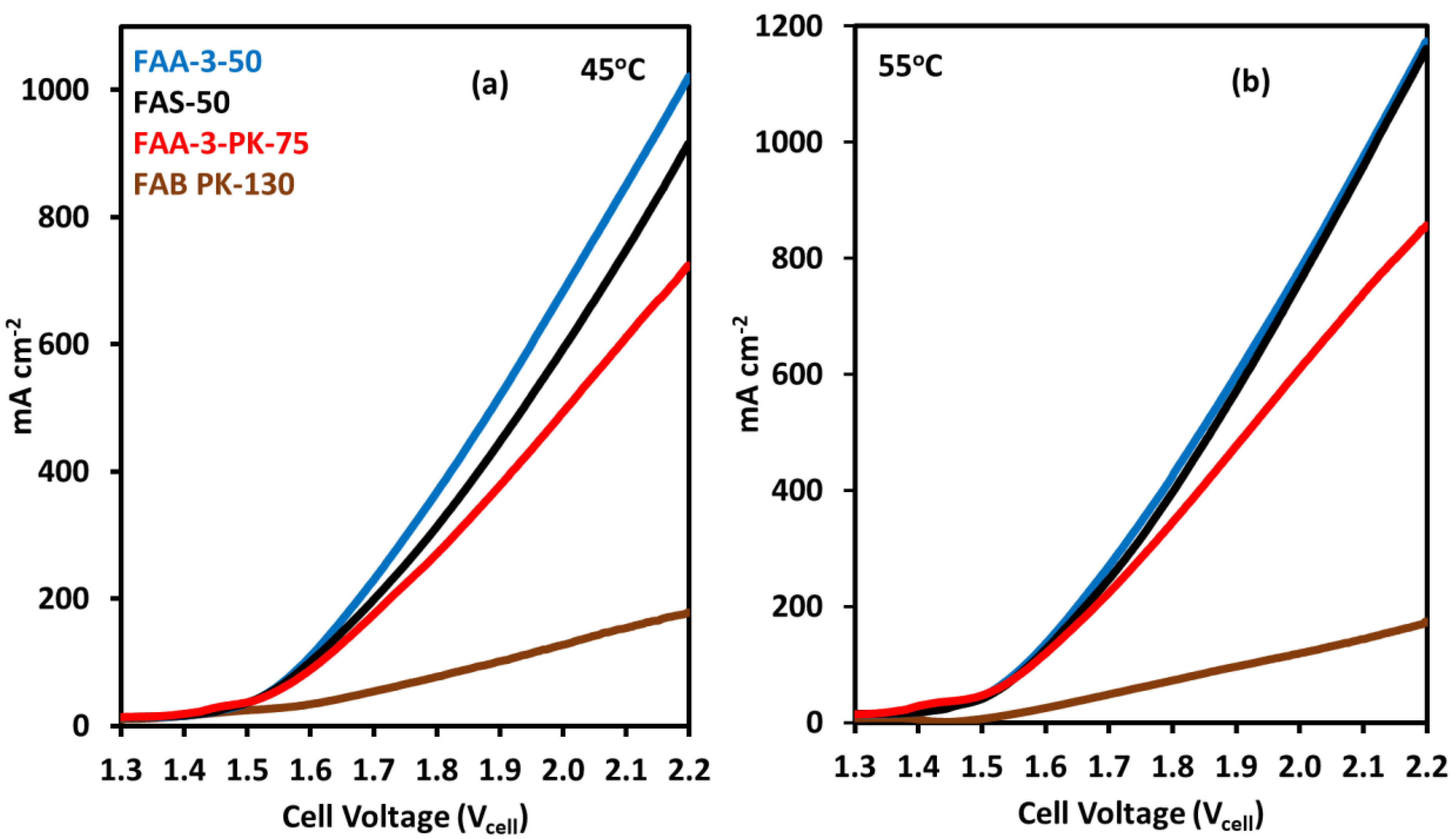
2.3. Effect of Anion Exchange Membranes on Electrolyzer Performance

Anion exchange membranes have a significant impact on the performance of AEM water electrolyzers, due to their critical role in their operation. The specific membrane choice can also play a large role in determining the electrolyzer performance. Several characteristics determine the performance of a specific membrane; however, specifically predicting and ranking these membranes requires experimental results and is often system-specific [38]. Maximizing ionic conductivity and stability while reducing specific resistance is essential to increase performance and viability. Mechanical stability frequently comes at the cost of reducing ionic conductivity and vice versa [39]. This is because thinner membranes frequently exhibit better OH transfer and lower mass transport resistance [40]. The membrane manufacturer Fumatech offers a wide range of membranes with different characteristics and performance. Out of these membranes, the following are of relevance to this study: FAA-3-50, FAS-50, FAA-3-PK-75, and FAB-PK-130.
The Fumasep FAA-3-50 is a membrane based on a brominated polysulfone backbone and uses quaternary ammonium (QA) sidechain groups [41]. All mentioned Fumatech membranes come with a Br counter ion; however, this can be altered as specified in their technical data sheet. FAA-3-50 is comparatively thin, at 45–55 µm. It has a very low specific area resistance at 0.6–1.5 Ω cm2 and has a high specific conductivity of 3–8 mS cm−1 [42]. Table 1 shows the specifications of Fumasep membranes from the membrane supplier; the conductivities and area-specific resistance of the membranes are reported in Cl form. The Fumasep FAS-50 membrane is composed of propriety hydrocarbon resin, and its composition is not available. This membrane is similar to FAA-3-50 in terms of performance specifications, with a thickness of 45–55 µm, specific area resistance of 0.6–1.5 Ω cm2, and a high specific conductivity of 3–8 mS cm−1 [43]. FAA-3-PK-75 is also based on a polysulfone backbone with the same QA sidechains, alongside a poly-ketone (PK) reinforcement, and has a thickness of 70–80 µm [44]. This thickness, alongside its high specific area resistance of 1.2–2.0 Ω cm2, results in a lower specific conductivity of 4.5–6.5 mS cm−1 [45]. The final membrane examined is FAB-PK-130, composed of PK-reinforced hydrocarbon resin [46]. This membrane was designed to have high mechanical stability and stability in acidic and basic environments. FAB-PK-130 is a much thicker membrane of 110–140 µm and, as a result, has a very high specific area resistance of 5.0–9.0 Ω cm2. This results in low specific conductivities of 1.0–2.5 mS cm−1. The conductivities of the Fumasep FAA-3-50 and X-37-50 membranes in KOH have been reported to be 40 and 80 mS cm−1, respectively, considerably higher than the membrane’s conductivity in chloride form [38].
For the comparison of electrolyzer activity with different AEMs, commercially available Fumasep membranes FAA-3-50, FAS-50, FAA-3-PK-75, and FAB PK-130 were used. AEM electrolysis was performed at 45 and 55 °C with 1 M KOH, using a NiFe2O4 catalyst at the anode and Pt/C catalyst at the cathode. FAA-3-50 MEA showed the highest current density of 1020 mA cm−2 at 2.2 V, as shown in Figure 7a. FAS-50 MEA showed similar activity, with a current density of 915 mA cm−2. The activity of FAA-3-PK-75 was also high, with a current density of 723 mA cm−2, but compared to other membranes, the activity was slightly lower. The lowest activity was that of the FAB PK-130 membrane, with a current density of 178 mA cm−2.
At 55 °C, the current density increased for each membrane but the trend in activity was the same as at 45 °C (Figure 7b). The MEAs with FAA-3-50 and FAS-50 achieve current densities of 1174 mA cm−2 and 1161 mA cm−2 at 2.2 V. For the FAA-3-PK-75 membrane, current density increased to 857 mA cm−2, which is an about 18% increase compared to the 45 °C operation. The current density did not increase for the FAB PK-130 membrane with the increase in temperature, which means that this membrane is the least active for AEM electrolysis compared to the other membranes used in this study.
The activities of the different membranes follow the trends predicted by their specific conductivity. The overall activity of an AEM electrolyzer is strongly influenced by the conductivity of the membrane, as it allows easier passage of ions with minimal resistance, resulting in greater current densities. The higher specific conductivity of FAA-3-50 and FAS-50 resulted in higher activity when compared to FAA-3-PK-75 and FAB PK-130. This is corroborated by the results, where the FAA-3-50 and FAS-50 membranes show higher activity at 2.2 V. The comparatively lower conductivity of FAA-3-PK-75, at 1.5 mS cm−1, which is approximately 19% lower compared to FAA-3-50 and FAS-50, resulted in notably reduced activity. The current density of 723 mA cm−2 achieved by the FAA-3-PK-75 membrane is lower than the current densities of FAA-3-50 and FAS-50 at 1020 mA cm−2 and 915 mA cm−2 respectively, showing an approximate decrease in activity of 29% and 21%. The reduced conductivity of FAB PK-130 resulted in a decrease in activity compared to all membranes.
Fumatech FAS-50, using a NiFe2O4 anode catalyst and a NiFeCo cathode in a 1 M KOH solution at 60 °C, achieved a current density of 250 mA cm−2 at 1.8 V and 900 mA cm−2 at 2 V [47]. The same catalysts and solutions achieved 240 mA cm−2 at 1.8 V using a FAA-3-50 membrane; current densities at 2 V were not provided. This is similar to the trends observed in this study, but with higher current densities and comparable results between FAS-50 and FAA-3-50.

2.3.1. EIS Effect of Voltage and Temperature

EIS analysis was performed on the AEM water electrolysis operation at a constant voltage; the analysis was performed at a temperature range of 45 °C and 55 °C. EIS analysis was performed to analyze the impedance associated with the electrolysis process [48]. This analysis can provide information on the kinetic and mass transport processes that take place at the cathode and anode. With this analysis, the resistance of the electrolyte and membrane electrode assembly can also be evaluated [49].
Figure 8a shows the Nyquist plot for the EIS analysis performed at 45 °C. AEM electrolysis was carried out using a NiFe2O4 catalyst at the anode and Pt/C at the cathode. At 2 V, the diameter of the semicircle in the Nyquist plot is smaller compared to that at 1.7 V operation, which shows that it has lower activation resistance compared to AEM electrolysis at low voltages. In the Nyquist plot, the (high-frequency region) x-intercept shows the ohmic resistance, and the second x-intercept shows the total resistance, which has contributions from ohmic resistance, activation resistance, and mass transport resistance [50]. Figure 8b shows a similar trend, but the ohmic and activation resistances are relatively lower at 55 °C.
The Nyquist plot obtained from the EIS analysis was fitted to the equivalent circuit model using the randomized simplex method, and the results are presented in Table 2. The software EC-Lab (version V11.36) was used to perform the equivalent circuit fitting. An electrical circuit is shown in Figure 8a, which represents the components of the AEM electrolyzer. R1 is the resistance due to the membrane or electrolyte, while R2 and R3 represent activation resistances at the electrodes for the OER and HER. Q2 and Q3 represent constant phase elements (CPEs) at the electrodes. L is the inductance due to the wires used to connect the AEM electrolyzer [51].
Table 2 shows that with the increase in temperature of the AEM electrolyzer, there is a decrease in ohmic resistance, which can enhance the overall efficiency of the electrolysis process. The ohmic resistance decreased due to the improved conductivity of hydroxyl ions with the increase in temperature [52]. Table 2 shows that as the temperature rose from 45 to 55 °C, the activation resistance at both the anode and cathode decreased, from 0.101 Ω to 0.075 Ω at 2 V and from 0.055 Ω to 0.031 Ω at 2 V. With the increase in temperature, the reaction kinetics of AEM electrolysis became faster as it overcame the kinetic barrier of the reactions at both the cathode and anode [53,54]. At each voltage, the operation at 55 °C shows lower ohmic resistance compared to the 45 °C electrolysis operation.
The effect of temperature on the resistance of an AEM electrolyzer can be found in some of the AEM electrolysis studies. One study utilizing a polybenzimidazole (PBI) AEM and NiFeOx and NiFeCo catalysts for the anode and cathode, respectively, in 1M KOH, found that at 1.9 V, the ohmic resistance decreased from 0.0178 Ω cm−2 at 30 °C to 0.0156 Ω cm−2 at 60 °C [31]. In the same study, the activation resistance lowered with an increase in temperature, decreasing from 0.023 Ω cm−2 at 30 °C to 0.0114 Ω cm−2. Two other studies, one utilizing Sustainion X37-50 and a NiFeCo cathode catalyst and the other FAA3-50 with a 40% Pt/C cathode catalyst, both in 1 M KOH, observed a decrease in both ohmic and activation resistance as the temperature increased from 30 °C to 60 °C [37,55].

2.3.2. EIS with Different Anion Exchange Membranes

Figure 9a,b show Nyquist plots at 55 °C for different membrane electrode assemblies at 1.7 V. The results of equivalent circuit fittings are presented in Table 3. The FAA-3-50 membrane showed the lowest activation resistance of 0.0756 Ω followed by FAS-50 with 0.0918 Ω. As for the other two membranes, FAA-3-PK-75 had an activation resistance of 0.113 Ω, and FAB-PK-130, which had very low electrolysis performance, had a very high activation resistance of 0.199 Ω. Similar trends were seen in ohmic resistance, with the lowest values for FAS-50 at 0.092 Ω and FAA-3-50 at 0.108 Ω. For AEM electrolysis, these membranes showed a comparable performance, which may be due to similar resistances offered during the operation. These results show that FAA-3-50 and FAS-50 had higher conductivities than the other AEMs under similar operating conditions. They also show that the membrane charge transfer between the membrane and catalyst layer is faster in these membranes compared to the low-performing membranes.
In our previous study using a Sustainion X-37-50 T membrane with a NiFeCoOx anode catalyst and a Pt/C cathode catalyst in 1 M KOH, at 2 V and at 70 °C, resistances of 0.064 Ω and 0.037 Ω were obtained for ohmic and activation resistance, respectively [56]. In the same study, using FAA-3-50 in an identical cell configuration resulted in resistances of 0.12 Ω and 0.054 Ω for ohmic and activation resistance, respectively. This trend continued in another study, where X-37-50 displayed a considerably lower resistance, possessing an activation resistance of 0.034 Ω compared to the 0.042 Ω of FAS-50, 0.056 Ω of the PiperION, and 0.070 Ω of FAA-3-50 at 50 °C in 1 M KOH using a NiFe-based catalyst at the anode and a 20 wt% Pt/C cathode catalyst [57].

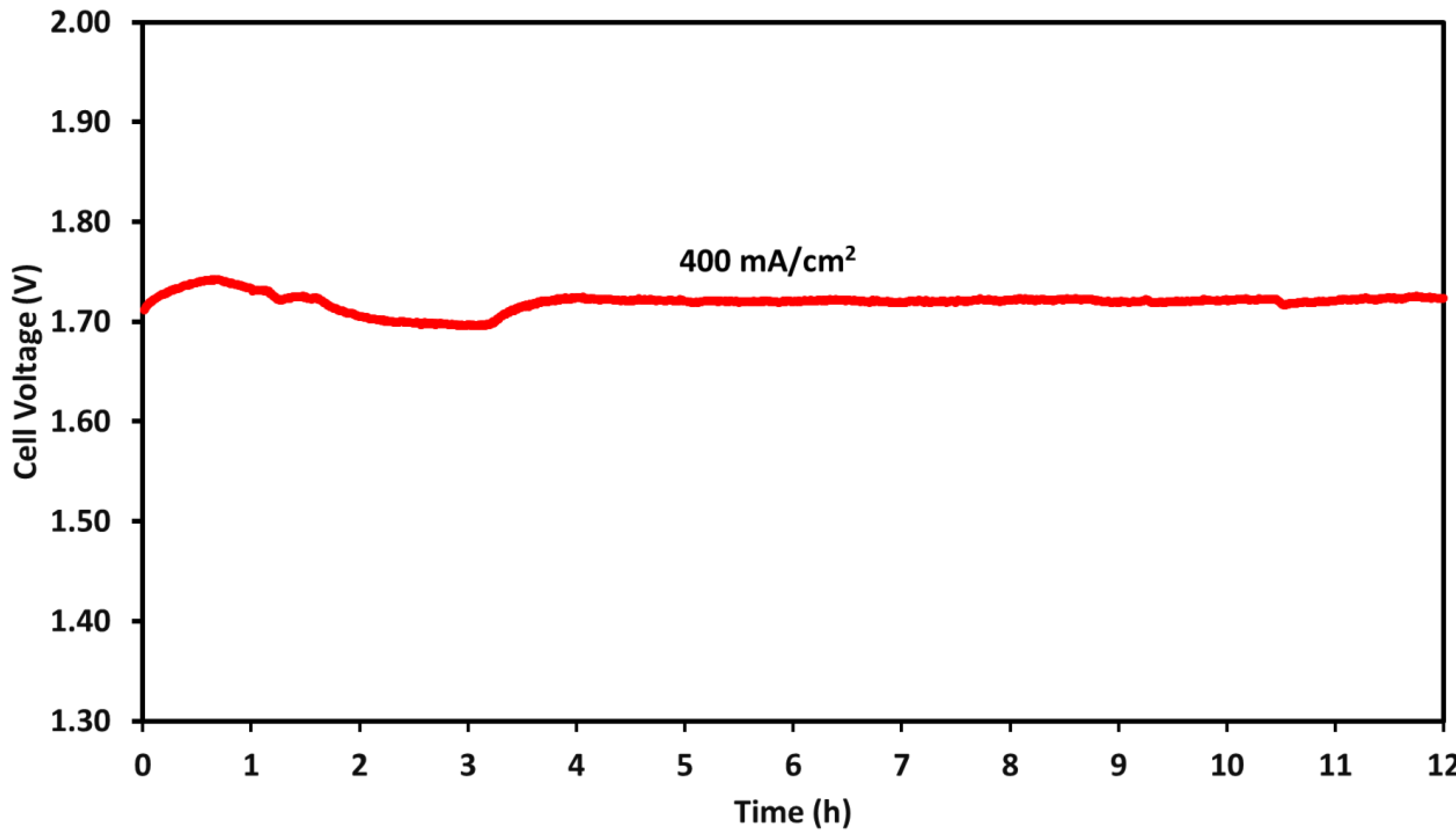
2.4. Durability Test

A durability test was performed for the AEM water electrolyzer using a NiFe2O4 catalyst at the anode. The electrolyzer was operated at 400 mA/cm2 for 12 h at 55 °C. Under these operating conditions, the cell efficiency was 72%, which was determined using Equation (1). A degradation rate of 0.833 mV/h was observed during the test, and the initial voltage was 1.71 V, which, after 12 h of continuous operation, increased to 1.72 V, as shown in Figure 10. The Faradic efficiency was 83%, calculated by dividing the amount of hydrogen obtained from the electrolyzer by the theoretical amount of hydrogen under these conditions. During stability testing, the electrolyzer’s performance remained stable.
The durability of AEMs affects the long-term testing of the electrolyzer operation, and commercial membranes have been reported to show losses in performance in long-term testing experiments in alkaline medium [58]. There are several key degradation pathways that are common, including various SN2 substitutions (benzyl, methyl), ring opening, nucleophilic substitution, dehydroflourination of the backbone, and nucleophilic addition and displacement, where specific mechanisms and the possibility of occurrence are determined by the composition of both the functional groups and backbone, as well as testing conditions [59,60]. The most commonly used functional groups, quaternary ammonium groups, are particularly susceptible to Hofmann elimination and nucleophilic substitution, which result in the degradation of cation groups and the formation of amines and olefins and amines and alcohols, respectively [61,62]. Another mechanism seen in various tetraalkylammonium hydroxides is chemical rearrangement caused by ylide formation [63,64,65]. Polymer backbones containing phenyl groups can experience degradation due to the oxidation of phenyl groups at OER potentials, leading to the formation of acidic phenols that can decrease solution pH and reduce conductivity [65,66]. A study by Arges et al. found that polysulfone-based backbones can become brittle and therefore mechanically unstable in alkaline solutions due to hydrolysis at both the ether and quaternary carbon groups when cation groups are attached to the benzyl position of the diphenyl propane group [63].
The deactivation of the catalysts can also cause voltage increases, which can occur due to a variety of factors. Changes in morphology are one such factor that has a significant impact on performance, where changes in structure can result in poor contact area between the catalyst and ionomer and reduce catalyst utilization [67]. Catalyst dissolution is another significant contributing factor in the deactivation of catalysts, where the catalysts dissolve into the electrolyte solution; this effect is typically intensified or promoted with electrolyzer operation as opposed to innately when in the electrolyte [68]. Passivation is a frequently seen deactivation method, wherein an insulating layer is formed between the catalyst and electrode, which inhibits the flow of electrons and therefore decreases cell performance [69,70]. In general, these factors typically depend on the specific catalyst used, and many such mechanisms are present at once, increasing and contributing to overall degradation [71].

3. Experimental

3.1. Synthesis of NiFeOx Catalyst

The catalysts were synthesized by the coprecipitation method at room temperature, using nickel nitrate hexahydrate (Ni(NO3)2·6H2O) and iron nitrate nonahydrate (Fe(NO3)3·9H2O) as precursors for nickel and iron, respectively. The Fe content varied from 5 wt% to 12.5 wt% for NiFeOx catalysts, and for NiFe2O4 catalysts, the Ni-to-Fe ratio was kept at 1:2. For 2 g of total metal content, the following precursor quantities were used: 9.411 g of Ni(NO3)2·6H2O and 0.722 g of Fe(NO3)3·9H2O for the 5 wt% Fe catalyst (yielding 1.900 g Ni and 0.100 g Fe); 9.158 g of nickel precursor and 1.084 g of iron precursor for 7.5 wt% Fe (1.850 g Ni and 0.150 g Fe); and 8.687 g of Ni(NO3)2·6H2O and 1.805 g of Fe(NO3)3·9H2O for the 12.5 wt% Fe formulation (1.750 g Ni and 0.250 g Fe). For NiFe2O4, 3.301 g of Ni(NO3)2·6H2O and 9.640 g of Fe(NO3)3·9H2O were used to yield 0.667 g Ni and 1.333 g Fe.
Both precursors were dissolved in deionized water at room temperature. Further, 1 M NaOH was used for precipitation and was added drop by drop until complete precipitation. The precipitate was then washed with water to remove excess NaOH and then centrifuged to collect the solid catalyst. The catalyst was then dried in an oven at 100 °C overnight to remove water. For both NiFeOx and NiFe2O4 catalysts, calcination was performed at 300 °C for 5 h.

3.2. Catalyst Testing in Three-Electrode System

Linear sweep voltammetry (LSV) and cyclic voltammetry (CV) were performed for OER and ECSA measurement using a potentiostat (VMP-3, Biologic, Seyssinet-Pariset, France). The OER three-electrode system consists of a graphite counter electrode, a standard calomel electrode (SCE) as a reference electrode, and a working electrode consisting of nickel foam with an area of 1 cm2 coated with the NiFeOx or NiFe2O4 catalyst. To fabricate the catalyst-coated electrode, catalyst ink was prepared by mixing the catalyst with a 5 wt% Nafion solution and ethanol. The thick catalyst slurry was then pasted on top of the nickel foam. The catalyst loading on nickel foam anode was 5 mg cm−2. LSV was performed with a scan rate of 5 mV s−1 and an iR correction of 85%. The voltages were converted to reversible hydrogen electrode (RHE) potential using the Nernst equation.
The NiFe2O4 catalyst’s long-term durability test for the OER was performed using a constant current density of 50 mA cm−2 over a time period of 600 h. The electrochemical surface area (ESCA) was estimated by dividing the double-layer capacitance (Cdl), obtained from cyclic voltammetry in 1M KOH at different scan rates in the non-Faradic region, by the smooth-plane capacitance (Cs) of a flat metal surface (40 μF/cm2). This ratio reflects the available surface area for electrochemical reactions, considering deviations from ideal behavior.

3.3. Preparation of Gas Diffusion Electrode

To a fabricate gas diffusion electrode (GDE) for the anode, a catalyst slurry was prepared using the catalyst, water, isopropanol, and Nafion solution (Nafion™ 1100W from Sigma Aldrich, St. Louis, MO, USA). The mixture was sonicated for 30 min to achieve a consistent composition. The catalyst slurry was then applied on the nickel foam (thickness of 1700 μm). Hot pressing was performed after catalyst coating to obtain a uniform surface and to achieve the desired thickness of the GDE. The Nafion content was 10 wt% of the total catalyst weight, and the catalyst loading was 25 mg cm−2. For the cathode, Pt/C(40 wt%, HISPEC 4000, Johnson Matthey, London, UK) was used, with a loading of 1 mg cm−2. The catalyst ink comprised a Pt/C catalyst, isopropanol, water, and Nafion. The Nafion was 20 wt% of the catalyst weight, and the cathode GDE was formed by air spraying the ink on carbon paper (Sigracet 29BC, Meitingen, Germany). The total active area of the electrodes was 3.24 cm2 at the cathode and anode, with the dimensions of 1.8 cm × 1.8 cm. The membrane electrode assembly was formed by combining the anode GDE, AEM, and cathode GDE.

3.4. AEM Electrolyzer Single-Cell Performance Test

For electrolyzer performance testing, a potentiostat connected to a 100 A booster (VMP3B-100, Seyssinet-Pariset, France) was used. LSV with a scan rate of 5 mV s−1 was used for AEM electrolysis. The electrolysis operation was also performed using chronoamperometry. The electrolyzer configuration was described in our earlier studies [56,72]. Briefly, a 1 M KOH electrolyte was circulated with a flow rate of 90 mL/min from the anode side. Electrochemical impedance spectroscopy was performed in a frequency range of 100 kHz to 100 mHz at a constant voltage.
To test the durability of AEM electrolysis with the X-37-50 T membrane and the NiFe2O4 catalyst, the test was carried out for 12 h at a current density of 400 mA cm−2. Equation (1) was used to calculate the efficiency of the electrolyzer. Faradaic efficiency was also calculated by quantifying the amount of hydrogen produced during electrolysis, where ΔH is the enthalpy of water splitting.
C e l l   e f f i c i e n c y ( % ) = m o l e s   o f   h y d r o g e n × Δ H × 100 A E M   e l e c t r o l y z e r   p o w e r   i n p u t

4. Conclusions

This study has demonstrated the effectiveness of NiFeOx and NiFe2O4 catalysts for AEM water electrolysis. NiFe2O4 displayed the highest catalytic activity for the OER, achieving a current density of 320 mA cm−2 at 2.0 V. It also had the lowest Tafel slope at 124 mV/dec, indicating that it possessed the most efficient electrochemical reaction kinetics. Low overpotentials of 416 and 409 mV were achieved for NiFe2O4 and NiFeOx (5%), respectively, at 10 mA cm−2. NiFe2O4 maintained stability and catalytic activity during the 600 h OER test at a high current density of 50 mA/cm2, and over the stability testing period, the degradation rate was 15 μV/h.
NiFe2O4 demonstrated the highest activity during AEM water electrolysis, with a current density of 1100 mA cm−2 at 2.2 V and 45 °C. Current density increased with the increase in electrolysis temperature to 55 °C, and all catalysts exhibited an increase in current density, with the NiFe2O4 catalyst achieving the highest current density of 1503 mA cm−2. Several Fumatech membranes were tested for AEM water electrolysis, including FAA-3-50, FAS-50, FAA-3-PK-75, and FAB PK-130. It was shown that the activity and effectiveness of these membranes are strongly correlated with their ionic conductivity. The most effective membranes were FAA-3-50 and FAS-50, which had comparable performance, whereas FAB PK-130 had the lowest activity compared to the other membranes.
Electrochemical impedance spectroscopy and equivalent circuit fitting analysis were performed on an AEM electrolyzer to examine the impact of various operating parameters. By increasing the temperature from 40 °C to 55 °C, the ohmic resistance reduces. The observed decrease in activation resistance at both the anode and cathode, coupled with improved OH ion conductivity, signifies faster reaction kinetics and lowered kinetic barriers. These findings highlight the positive impact of temperature elevation on AEM electrolysis. EIS results at 55 °C and 1.7 V for various membrane electrode assemblies highlight distinct performance characteristics. FAA-3-50 and FAS-50 membranes showed lower activation and ohmic resistances, indicative of higher conductivity and faster membrane charge transfer. FAA-3-PK-75 exhibited intermediate performance, while FAB-PK-130 demonstrated poor AEM electrolysis performance, with significantly higher resistances.
The 12 h durability test for the AEM electrolyzers demonstrated robust stability, with a minimal degradation rate of 0.833 mV/h. Throughout the test, the initial voltage of 1.71 V only increased marginally to 1.72 V. The energy efficiency, evaluated at 400 mA/cm2, was 72%, indicating efficient hydrogen production during the entire duration of the durability test.

Supplementary Materials

The following supporting information can be downloaded at: https://www.mdpi.com/article/10.3390/molecules30153228/s1.

Author Contributions

Conceptualization, methodology, data curation, writing—original draft, and visualization, K.W.A.; writing—original draft, A.D.; SEM analysis, S.H.; conceptualization, methodology, supervision, project administration, and funding acquisition, M.F. All authors have read and agreed to the published version of the manuscript.

Funding

This research received no external funding.

Data Availability Statement

Data are contained within the article and Supplementary Materials.

Acknowledgments

This work was supported by the Department of Chemical Engineering at the University of Waterloo, Canada Research Chair Tier I—Zero-Emission Vehicles and Hydrogen Energy Systems Grant number: 950-232215, and the Natural Sciences and Engineering Research Council of Canada (NSERC), Discovery Grants Program, RGPIN-2020-04149.

Conflicts of Interest

The authors declare that they have no known competing financial interests or personal relationships that could have appeared to influence the work reported in this paper.

References

  1. Yue, M.; Lambert, H.; Pahon, E.; Roche, R.; Jemei, S.; Hissel, D. Hydrogen Energy Systems: A Critical Review of Technologies, Applications, Trends and Challenges. Renew. Sustain. Energy Rev. 2021, 146, 111180. [Google Scholar] [CrossRef]
  2. Züttel, A.; Remhof, A.; Borgschulte, A.; Friedrichs, O. Hydrogen: The Future Energy Carrier. Philos. Trans. R. Soc. A Math. Phys. Eng. Sci. 2010, 368, 3329–3342. [Google Scholar] [CrossRef]
  3. Mazloomi, K.; Gomes, C. Hydrogen as an Energy Carrier: Prospects and Challenges. Renew. Sustain. Energy Rev. 2012, 16, 3024–3033. [Google Scholar] [CrossRef]
  4. Johnston, B.; Mayo, M.C.; Khare, A. Hydrogen: The Energy Source for the 21st Century. Technovation 2005, 25, 569–585. [Google Scholar] [CrossRef]
  5. Tang, D.; Tan, G.-L.; Li, G.-W.; Liang, J.-G.; Ahmad, S.M.; Bahadur, A.; Humayun, M.; Ullah, H.; Khan, A.; Bououdina, M. State-of-the-Art Hydrogen Generation Techniques and Storage Methods: A Critical Review. J. Energy Storage 2023, 64, 107196. [Google Scholar] [CrossRef]
  6. Cho, H.H.; Strezov, V.; Evans, T.J. Environmental Impact Assessment of Hydrogen Production via Steam Methane Reforming Based on Emissions Data. Energy Rep. 2022, 8, 13585–13595. [Google Scholar] [CrossRef]
  7. Bhandari, R.; Trudewind, C.A.; Zapp, P. Life Cycle Assessment of Hydrogen Production via Electrolysis—A Review. J. Clean. Prod. 2014, 85, 151–163. [Google Scholar] [CrossRef]
  8. Shiva Kumar, S.; Lim, H. An Overview of Water Electrolysis Technologies for Green Hydrogen Production. Energy Rep. 2022, 8, 13793–13813. [Google Scholar] [CrossRef]
  9. Xu, Q.; Zhang, L.; Zhang, J.; Wang, J.; Hu, Y.; Jiang, H.; Li, C. Anion Exchange Membrane Water Electrolyzer: Electrode Design, Lab-Scaled Testing System and Performance Evaluation. EnergyChem 2022, 4, 100087. [Google Scholar] [CrossRef]
  10. Zhang, K.; Liang, X.; Wang, L.; Sun, K.; Wang, Y.; Xie, Z.; Wu, Q.; Bai, X.; Hamdy, M.S.; Chen, H.; et al. Status and Perspectives of Key Materials for PEM Electrolyzer. Nano Res. Energy 2022, 1, e9120032. [Google Scholar] [CrossRef]
  11. Shiva Kumar, S.; Himabindu, V. Hydrogen Production by PEM Water Electrolysis—A Review. Mater. Sci. Energy Technol. 2019, 2, 442–454. [Google Scholar] [CrossRef]
  12. Yang, J.; Jang, M.J.; Zeng, X.; Park, Y.S.; Lee, J.; Choi, S.M.; Yin, Y. Non-Precious Electrocatalysts for Oxygen Evolution Reaction in Anion Exchange Membrane Water Electrolysis: A Mini Review. Electrochem. Commun. 2021, 131, 107118. [Google Scholar] [CrossRef]
  13. Liu, J.; Kang, Z.; Li, D.; Pak, M.; Alia, S.M.; Fujimoto, C.; Bender, G.; Kim, Y.S.; Weber, A.Z. Elucidating the Role of Hydroxide Electrolyte on Anion-Exchange-Membrane Water Electrolyzer Performance. J. Electrochem. Soc. 2021, 168, 054522. [Google Scholar] [CrossRef]
  14. Park, S.; Park, J.E.; Na, G.; Choi, C.; Cho, Y.-H.; Sung, Y.-E. Low-Cost and High-Performance Anion-Exchange Membrane Water Electrolysis Stack Using Non-Noble Metal-Based Materials. ACS Appl. Energy Mater. 2023, 6, 8738–8748. [Google Scholar] [CrossRef]
  15. Vincent, I.; Bessarabov, D. Low Cost Hydrogen Production by Anion Exchange Membrane Electrolysis: A Review. Renew. Sustain. Energy Rev. 2018, 81, 1690–1704. [Google Scholar] [CrossRef]
  16. Palmas, S.; Rodriguez, J.; Mais, L.; Mascia, M.; Herrando, M.C.; Vacca, A. Anion Exchange Membrane: A Valuable Perspective in Emerging Technologies of Low Temperature Water Electrolysis. Curr. Opin. Electrochem. 2023, 37, 101178. [Google Scholar] [CrossRef]
  17. Kang, S.Y.; Park, J.E.; Jang, G.Y.; Kim, O.-H.; Kwon, O.J.; Cho, Y.-H.; Sung, Y.-E. High-Performance and Durable Water Electrolysis Using a Highly Conductive and Stable Anion-Exchange Membrane. Int. J. Hydrogen Energy 2022, 47, 9115–9126. [Google Scholar] [CrossRef]
  18. Soltani, M.; Amin, H.M.A.; Cebe, A.; Ayata, S.; Baltruschat, H. Metal-Supported Perovskite as an Efficient Bifunctional Electrocatalyst for Oxygen Reduction and Evolution: Substrate Effect. J. Electrochem. Soc. 2021, 168, 034504. [Google Scholar] [CrossRef]
  19. Amin, H.M.A.; Apfel, U. Metal-Rich Chalcogenides as Sustainable Electrocatalysts for Oxygen Evolution and Reduction: State of the Art and Future Perspectives. Eur. J. Inorg. Chem. 2020, 2020, 2679–2690. [Google Scholar] [CrossRef]
  20. Amin, H.M.A.; Zan, L.; Baltruschat, H. Boosting the Bifunctional Catalytic Activity of Co3O4 on Silver and Nickel Substrates for the Alkaline Oxygen Evolution and Reduction Reactions. Surf. Interfaces 2024, 54, 105218. [Google Scholar] [CrossRef]
  21. Sathiyan, K.; Mukherjee, P.; Higashimine, K.; Taniike, T. Durability Meets Performance: A LaCoO3–MoS2 Composite for Electrochemical Overall Water Splitting. Energy Fuels 2025, 39, 13606–13617. [Google Scholar] [CrossRef]
  22. Dalai, N.; Mohanty, B.; Mitra, A.; Jena, B. Highly Active Ternary Nickel–Iron Oxide as Bifunctional Catalyst for Electrochemical Water Splitting. ChemistrySelect 2019, 4, 7791–7796. [Google Scholar] [CrossRef]
  23. Liu, G.; Wang, K.; Gao, X.; He, D.; Li, J. Fabrication of Mesoporous NiFe2O4 Nanorods as Efficient Oxygen Evolution Catalyst for Water Splitting. Electrochim. Acta 2016, 211, 871–878. [Google Scholar] [CrossRef]
  24. Liu, G.; Gao, X.; Wang, K.; He, D.; Li, J. Uniformly Mesoporous NiO/NiFe2O4 Biphasic Nanorods as Efficient Oxygen Evolving Catalyst for Water Splitting. Int. J. Hydrogen Energy 2016, 41, 17976–17986. [Google Scholar] [CrossRef]
  25. Feng, Z.; Wang, P.; Cheng, Y.; Mo, Y.; Luo, X.; Liu, P.; Guo, R.; Liu, X. Recent Progress on NiFe2O4 Spinels as Electrocatalysts for the Oxygen Evolution Reaction. J. Electroanal. Chem. 2023, 946, 117703. [Google Scholar] [CrossRef]
  26. Zhu, J.; Zhang, Q.; Zhao, P.; Chen, L.; Yang, S.; Yan, Q.; Li, H. NiFe2O4 @Co3O4 Heterostructure with Abundant Oxygen Vacancies as a Bifunctional Electrocatalyst for Overall Water Splitting. J. Alloys Compd. 2022, 918, 165705. [Google Scholar] [CrossRef]
  27. Amin, H.M.A.; Attia, M.; Tetzlaff, D.; Apfel, U. Tailoring the Electrocatalytic Activity of Pentlandite FexNi9-XS8 Nanoparticles via Variation of the Fe : Ni Ratio for Enhanced Water Oxidation. ChemElectroChem 2021, 8, 3863–3874. [Google Scholar] [CrossRef]
  28. Liu, Z.; Sajjad, S.D.; Gao, Y.; Yang, H.; Kaczur, J.J.; Masel, R.I. The Effect of Membrane on an Alkaline Water Electrolyzer. Int. J. Hydrogen Energy 2017, 42, 29661–29665. [Google Scholar] [CrossRef]
  29. Kutz, R.B.; Chen, Q.; Yang, H.; Sajjad, S.D.; Liu, Z.; Masel, I.R. Sustainion Imidazolium-Functionalized Polymers for Carbon Dioxide Electrolysis. Energy Technol. 2017, 5, 929–936. [Google Scholar] [CrossRef]
  30. Noor Azam, A.M.I.; Ragunathan, T.; Zulkefli, N.N.; Masdar, M.S.; Majlan, E.H.; Mohamad Yunus, R.; Shamsul, N.S.; Husaini, T.; Shaffee, S.N.A. Investigation of Performance of Anion Exchange Membrane (AEM) Electrolysis with Different Operating Conditions. Polymers 2023, 15, 1301. [Google Scholar] [CrossRef]
  31. Vincent, I.; Lee, E.-C.; Kim, H.-M. Comprehensive Impedance Investigation of Low-Cost Anion Exchange Membrane Electrolysis for Large-Scale Hydrogen Production. Sci. Rep. 2021, 11, 293. [Google Scholar] [CrossRef] [PubMed]
  32. Vincent, I.; Kruger, A.; Bessarabov, D. Development of Efficient Membrane Electrode Assembly for Low Cost Hydrogen Production by Anion Exchange Membrane Electrolysis. Int. J. Hydrogen Energy 2017, 42, 10752–10761. [Google Scholar] [CrossRef]
  33. Park, J.E.; Kang, S.Y.; Oh, S.-H.; Kim, J.K.; Lim, M.S.; Ahn, C.-Y.; Cho, Y.-H.; Sung, Y.-E. High-Performance Anion-Exchange Membrane Water Electrolysis. Electrochim. Acta 2019, 295, 99–106. [Google Scholar] [CrossRef]
  34. Chakik, F.E.; Kaddami, M.; Mikou, M. Optimization of Physico-Chemical Parameters of Hydrogen Production by Electrolysis of Water. In Proceedings of the 2018 Renewable Energies, Power Systems & Green Inclusive Economy (REPS-GIE), Casablanca, Morocco, 23–24 April 2018. [Google Scholar]
  35. Motealleh, B.; Liu, Z.; Masel, R.I.; Sculley, J.P.; Richard Ni, Z.; Meroueh, L. Next-Generation Anion Exchange Membrane Water Electrolyzers Operating for Commercially Relevant Lifetimes. Int. J. Hydrogen Energy 2021, 46, 3379–3386. [Google Scholar] [CrossRef]
  36. Chen, M.; Mandal, M.; Groenhout, K.; McCool, G.; Tee, H.M.; Zulevi, B.; Kohl, P.A. Self-Adhesive Ionomers for Durable Low-Temperature Anion Exchange Membrane Electrolysis. J. Power Sources 2022, 536, 231495. [Google Scholar] [CrossRef]
  37. Caprì, A.; Gatto, I.; Lo Vecchio, C.; Trocino, S.; Carbone, A.; Baglio, V. Anion Exchange Membrane Water Electrolysis Based on Nickel Ferrite Catalysts. ChemElectroChem 2022, 10, e202201056. [Google Scholar] [CrossRef]
  38. Henkensmeier, D.; Najibah, M.; Harms, C.; Žitka, J.; Hnát, J.; Bouzek, K. Overview: State-of-the Art Commercial Membranes for Anion Exchange Membrane Water Electrolysis. J. Electrochem. Energy Convers. Storage 2020, 18, 024001. [Google Scholar] [CrossRef]
  39. Santoro, C.; Lavacchi, A.; Mustarelli, P.; Di Noto, V.; Elbaz, L.; Dekel, D.R.; Jaouen, F. What Is Next in Anion-Exchange Membrane Water Electrolyzers? Bottlenecks, Benefits, and Future. ChemSusChem 2022, 15, e202200027. [Google Scholar] [CrossRef]
  40. Pushkareva, I.V.; Pushkarev, A.S.; Grigoriev, S.A.; Modisha, P.; Bessarabov, D.G. Comparative Study of Anion Exchange Membranes for Low-Cost Water Electrolysis. Int. J. Hydrogen Energy 2020, 45, 26070–26079. [Google Scholar] [CrossRef]
  41. Lo Vecchio, C.; Carbone, A.; Gatto, I.; Baglio, V. Investigation of Fumasep® FAA3-50 Membranes in Alkaline Di-rect Methanol Fuel Cells. Polymers 2023, 15, 1555. [Google Scholar] [CrossRef]
  42. Fumasep FAA-3-50. Available online: https://www.fuelcellstore.com/fumasep-faa-3-50 (accessed on 27 October 2023).
  43. Fumasep FAS-50. Available online: https://www.fuelcellstore.com/fumasep-fas-50 (accessed on 27 October 2023).
  44. Lee, S.A.; Kim, J.; Kwon, K.C.; Park, S.H.; Jang, H.W. Anion Exchange Membrane Water Electrolysis for Sustaina-ble Large-scale Hydrogen Production. Carbon Neutralization 2022, 1, 26–48. [Google Scholar] [CrossRef]
  45. Fumasep FAA-3-PK-75. Available online: https://www.fuelcellstore.com/fumasep-faa-3-pk-75 (accessed on 27 October 2023).
  46. Fumasep FAB-PK-130. Available online: https://www.fuelcellstore.com/fumasep-fab (accessed on 27 October 2023).
  47. Caprì, A.; Martínez-Lázaro, A.; Béjar, J.; Gatto, I.; Álvarez-Contreras, L.; Gurrola, M.P.; Ledesma-García, J.; Bag-lio, V.; Arriaga, L.G. Three-Dimensionally Ordered Macroporous Trimetallic Spinel for Anion Exchange Mem-brane Water Electrolysis. Electrochim. Acta 2023, 463, 142851. [Google Scholar] [CrossRef]
  48. Siracusano, S.; Trocino, S.; Briguglio, N.; Baglio, V.; Aricò, A.S. Electrochemical Impedance Spectroscopy as a Diagnostic Tool in Polymer Electrolyte Membrane Electrolysis. Materials 2018, 11, 1368. [Google Scholar] [CrossRef] [PubMed]
  49. van der Merwe, J.; Uren, K.; van Schoor, G.; Bessarabov, D. Characterisation Tools Development for PEM Electro-lysers. Int. J. Hydrogen Energy 2014, 39, 14212–14221. [Google Scholar] [CrossRef]
  50. Kang, Z.; Yang, G.; Mo, J.; Yu, S.; Cullen, D.A.; Retterer, S.T.; Toops, T.J.; Brady, M.P.; Bender, G.; Pivovar, B.S.; et al. Developing Titanium Micro/Nano Porous Layers on Planar Thin/Tunable LGDLs for High-Efficiency Hydrogen Production. Int. J. Hydrogen Energy 2018, 43, 14618–14628. [Google Scholar] [CrossRef]
  51. Khan, S.; Rizvi, S.M.A.; Urooj, S. Equivalent Circuit Modelling Using Electrochemical Impedance Spectroscopy for Different Materials of SOFC. In Proceedings of the 2016 3rd International Conference on Computing for Sustainable Global Development (INDIACom), New Delhi, India, 16–18 March 2016; pp. 1563–1567. [Google Scholar]
  52. Zeng, L.; Zhao, T.S. Integrated Inorganic Membrane Electrode Assembly with Layered Double Hydroxides as Ion-ic Conductors for Anion Exchange Membrane Water Electrolysis. Nano Energy 2015, 11, 110–118. [Google Scholar] [CrossRef]
  53. Seetharaman, S.; Balaji, R.; Ramya, K.; Dhathathreyan, K.S.; Velan, M. Graphene Oxide Modified Non-Noble Met-al Electrode for Alkaline Anion Exchange Membrane Water Electrolyzers. Int. J. Hydrogen Energy 2013, 38, 14934–14942. [Google Scholar] [CrossRef]
  54. Lim, A.; Cho, M.K.; Lee, S.Y.; Kim, H.-J.; Yoo, S.J.; Sung, Y.-E.; Jang, J.H.; Park, H.S. A Review of Industrially De-veloped Components and Operation Conditions for Anion Exchange Membrane Water Electrolysis. J. Electrochem. Sci. Technol. 2017, 8, 265–273. [Google Scholar] [CrossRef]
  55. Wu, Z.; Zou, Z.; Huang, J.; Gao, F. NiFe2O4 Nanoparticles/NiFe Layered Double-Hydroxide Nanosheet Hetero-structure Array for Efficient Overall Water Splitting at Large Current Densities. ACS Appl. Mater. Interfaces 2018, 10, 26283–26292. [Google Scholar] [CrossRef]
  56. Ahmed, K.W.; Jang, M.J.; Habibpour, S.; Chen, Z.; Fowler, M. NiFeOx and NiFeCoOx Catalysts for Anion Exchange Membrane Water Electrolysis. Electrochem 2022, 3, 843–861. [Google Scholar] [CrossRef]
  57. Kong, T.-H.; Thangavel, P.; Shin, S.; Kwon, S.; Choi, H.; Lee, H.; Park, N.; Woo, J.-J.; Kwon, Y. In-Situ Ionomer-Free Catalyst-Coated Membranes for Anion Exchange Membrane Water Electrolyzers. ACS Energy Lett. 2023, 8, 4666–4673. [Google Scholar] [CrossRef]
  58. Li, D.; Motz, A.R.; Bae, C.; Fujimoto, C.; Yang, G.; Zhang, F.-Y.; Ayers, K.E.; Kim, Y.S. Durability of Anion Exchange Membrane Water Electrolyzers. Energy Environ. Sci. 2021, 14, 3393–3419. [Google Scholar] [CrossRef]
  59. Du, N.; Roy, C.; Peach, R.; Turnbull, M.; Thiele, S.; Bock, C. Anion-Exchange Membrane Water Electrolyzers. Chem. Rev. 2022, 122, 11830–11895. [Google Scholar] [CrossRef] [PubMed]
  60. Mustain, W.E.; Chatenet, M.; Page, M.; Kim, Y.S. Durability Challenges of Anion Exchange Membrane Fuel Cells. Energy Environ. Sci. 2020, 13, 2805–2838. [Google Scholar] [CrossRef]
  61. Wierzbicki, S.; Douglin, J.C.; Kostuch, A.; Dekel, D.R.; Kruczała, K. Are Radicals Formed During Anion-Exchange Membrane Fuel Cell Operation? J. Phys. Chem. Lett. 2020, 11, 7630–7636. [Google Scholar] [CrossRef]
  62. Couture, G.; Alaaeddine, A.; Boschet, F.; Ameduri, B. Polymeric Materials as Anion-Exchange Membranes for Alkaline Fuel Cells. Prog. Polym. Sci. 2011, 36, 1521–1557. [Google Scholar] [CrossRef]
  63. Arges, C.G.; Ramani, V. Two-Dimensional NMR Spectroscopy Reveals Cation-Triggered Backbone Degradation in Polysulfone-Based Anion Exchange Membranes. Proc. Natl. Acad. Sci. USA 2013, 110, 2490–2495. [Google Scholar] [CrossRef]
  64. Merle, G.; Wessling, M.; Nijmeijer, K. Anion Exchange Membranes for Alkaline Fuel Cells: A Review. J. Membr. Sci. 2011, 377, 1–35. [Google Scholar] [CrossRef]
  65. Li, D.; Park, E.J.; Zhu, W.; Shi, Q.; Zhou, Y.; Tian, H.; Lin, Y.; Serov, A.; Zulevi, B.; Baca, E.D.; et al. Highly Quaternized Polystyrene Ionomers for High Performance Anion Exchange Membrane Water Electrolysers. Nat. Energy 2020, 5, 378–385. [Google Scholar] [CrossRef]
  66. Leonard, D.P.; Lehmann, M.; Klein, J.M.; Matanovic, I.; Fujimoto, C.; Saito, T.; Kim, Y.S. Phenyl-Free Poly-norbornenes for Potential Anion Exchange Ionomers for Fuel Cells and Electrolyzers. Adv. Energy Mater. 2022, 13, 2203488. [Google Scholar] [CrossRef]
  67. Lei, C.; Yang, K.; Wang, G.; Wang, G.; Lu, J.; Xiao, L.; Zhuang, L. Impact of Catalyst Reconstruction on the Durability of Anion Exchange Membrane Water Electrolysis. ACS Sustain. Chem. Eng. 2022, 10, 16725–16733. [Google Scholar] [CrossRef]
  68. Chen, R.; Hung, S.; Zhou, D.; Gao, J.; Yang, C.; Tao, H.; Yang, H.B.; Zhang, L.; Zhang, L.; Xiong, Q.; et al. Layered Structure Causes Bulk NiFe Layered Double Hydroxide Unstable in Alkaline Oxygen Evolution Reaction. Adv. Mater. 2019, 31, 1903909. [Google Scholar] [CrossRef]
  69. Jang, H.; Chung, S.; Lee, J. In Situ Demonstration of Anodic Interface Degradation during Water Electrolysis: Corrosion and Passivation. Electrochim. Acta 2021, 365, 137276. [Google Scholar] [CrossRef]
  70. Singh, S.K.; Takeyasu, K.; Paul, B.; Sharma, S.K.; Nakamura, J. CoOx Electro-Catalysts Anchored on Nitro-gen-Doped Carbon Nanotubes for the Oxygen Evolution Reaction. Sustain. Energy Fuels 2021, 5, 820–827. [Google Scholar] [CrossRef]
  71. Berenguer, R.; La Rosa-Toro, A.; Quijada, C.; Morallón, E. Origin of the Deactivation of Spinel CuxCo3−xO4/Ti Anodes Prepared by Thermal Decomposition. J. Phys. Chem. C 2008, 112, 16945–16952. [Google Scholar] [CrossRef]
  72. Ahmed, K.W.; Habibpour, S.; Chen, Z.; Fowler, M. Investigation of NiCoOx Catalysts for Anion Exchange Membrane Water Electrolysis: Performance, Durability, and Efficiency Analysis. J. Energy Storage 2024, 79, 110149. [Google Scholar] [CrossRef]
Figure 1. (a) SEM of nickel foam anode GDL; (b) cross-section of NiFe2O4 catalyst-coated nickel foam anode; (c) EDS of NiFe2O4 catalyst, which shows the ratio of Ni to Fe of about 1:2.
Molecules 30 03228 g001
Figure 2. XRD of NiFeOx and NiFe2O4 catalysts.
Molecules 30 03228 g002
Figure 3. OER at room temperature in 1 M KOH with NiFe2O4 and NiFeOx catalysts: (a) LSV (85% iR-corrected); (b) chronoamperometry in current density range of 10 to 100 mA/cm2; (c) Tafel plots for OER; (d) catalyst Catalyst durability test for 600 h at current density of 50 mA/cm2 using NiFe2O4 catalyst at anode.
Molecules 30 03228 g003
Figure 4. Cyclic voltammetry at different scan rates; the analysis was performed in non-Faradic region. (a) NiFeOx (5% Fe); (b) NiFeOx (7.5% Fe); (c) NiFeOx (12.5% Fe); (d) NiFe2O4.
Molecules 30 03228 g004
Figure 5. Double-layer capacitance (Cdl) plot of scan rate vs. current density for NiFeOx and NiFe2O4 catalysts.
Molecules 30 03228 g005
Figure 6. Linear sweep voltammetry in a temperature range of (a) 45 °C and (b) 55 °C. NiFeOx and NiFe2O4 catalysts were used at the anode. X-37-50 T membrane was used for AEM electrolysis; (c) chronoamperometry in a voltage range of 1.5 to 2.3 V at 45 °C and 55 °C, with NiFe2O4 catalysts.
Molecules 30 03228 g006
Figure 7. AEM electrolysis comparison using FAA-3-50, FAS-50, FAA-3-PK-75, and FAB PK-130 membranes at (a) 45 °C and (b) 55 °C, with NiFe2O4 catalyst at anode and 1 M KOH as electrolyte.
Molecules 30 03228 g007
Figure 8. Nyquist plots for NiFe2O4 catalyst using FAA-3-50 membrane for water electrolysis at (a) 45 °C and (b) 55 °C.
Molecules 30 03228 g008
Figure 9. Nyquist plots for AEM electrolysis operation at 1.7 V with NiFe2O4 catalyst at 55 °C with (a) FAS-50, FAA-3-50 and FAA-3-PK-75 membranes and (b) FAB-PK-130 membrane.
Molecules 30 03228 g009
Figure 10. AEM electrolyzer durability test at 400 mA/cm2 for 12 h in 1 M KOH using NiFe2O4 catalyst at the anode; electrolyzer was operated at 55 °C using X-37-50 grade T membrane.
Molecules 30 03228 g010
Table 1. Specifications of Fumasep membranes [42,43,45,46].
MembraneThickness ( μm)Specific Conductivity in Cl (mS cm−1)Specific Area Resistance (Ω cm−2)
FAA-3-5045–553–80.6–1.5
FAS-5045–553–80.6–1.5
FAA-3-PK-7570–804.5–6.51.2–2
FAB PK-130110–1401–2.55–9
Table 2. Results from fitting an equivalent circuit during electrolysis operations at temperatures of 45 °C and 55 °C using FAA-3-50 membrane, with NiFe2O4 catalyst.
TemperatureOhmic ResistanceActivation Resistance
Rohm (Ω)Ranode + Rcathode (Ω)
1.7 V
45 °C0.1270.101
55 °C0.1080.075
1.8 V
45 °C0.1330.077
55 °C0.0930.071
1.9 V
45 °C0.1340.051
55 °C0.1160.036
2 V
45 °C0.1340.055
55 °C0.1170.031
Table 3. Resistances evaluated from equivalent circuit fittings for AEM water electrolysis using different membranes with NiFe2O4 catalyst at 1.7 V.
MembranesOhmic ResistanceActivation Resistance
Rohm (Ω)Ranode + Rcathode (Ω)
FAA-3-500.1080.0756
FAS-500.0920.0918
FAA-3-PK-750.160.113
FAB-PK-1300.7770.199
Disclaimer/Publisher’s Note: The statements, opinions and data contained in all publications are solely those of the individual author(s) and contributor(s) and not of MDPI and/or the editor(s). MDPI and/or the editor(s) disclaim responsibility for any injury to people or property resulting from any ideas, methods, instructions or products referred to in the content.

