Article

Nickel-Rich Cathodes for Solid-State Lithium Batteries: Comparative Study Between PVA and PIB Binders

by
José M. Pinheiro
1,
Beatriz Moura Gomes
1,2,
Manuela C. Baptista
1,2 and
M. Helena Braga
1,2,*
1
Engineering Faculty, University of Porto, R. Dr. Roberto Frias s/n, 4200-465 Porto, Portugal
2
LAETA, Institute of Science and Innovation in Mechanical and Industrial Engineering, R. Dr. Roberto Frias 400, 4200-465 Porto, Portugal
*
Author to whom correspondence should be addressed.
Molecules 2025, 30(14), 2974; https://doi.org/10.3390/molecules30142974
Submission received: 21 June 2025 / Revised: 9 July 2025 / Accepted: 11 July 2025 / Published: 15 July 2025

Abstract

The growing demand for high-energy, safe, and sustainable lithium-ion batteries has increased interest in nickel-rich cathode materials and solid-state electrolytes. This study presents a scalable wet-processing method for fabricating composite cathodes for all-solid-state batteries. The cathodes studied herein are high-nickel LiNi0.90Mn0.05Co0.05O2, NMC955, the sulfide-based electrolyte Li6PS5Cl, and alternative binders—polyvinyl alcohol (PVA) and polyisobutylene (PIB)—dispersed in toluene, a non-polar solvent compatible with the electrolyte. After fabrication, the cathodes were characterized using SEM/EDX, sheet resistance, and Hall effect measurements. Electrochemical tests were additionally performed in all-solid-state battery half-cells comprising the synthesized cathodes, lithium metal anodes, and Li6PS5Cl as the separator and electrolyte. The results show that both PIB and PVA formulations yielded conductive cathodes with stable microstructures and uniform particle distribution. Electrochemical characterization exposed that the PVA-based cathode outperformed the PIB-based counterpart, achieving the theoretical capacity of 192 mAh·g−1 even at 1C, whereas the PIB cathode reached a maximum capacity of 145 mAh.g−1 at C/40. Post-mortem analysis confirmed the structural integrity of the cathodes. These findings demonstrate the viability of NMC955 as a high-capacity cathode material compatible with solid-state systems.

1. Introduction

Lithium-ion batteries (LIBs) redefined energy storage, serving as the primary power source for electric vehicles (EVs) and consumer electronics [1]. Traditional LIBs are approaching their technological limit, constrained by conventional cathode active materials (CAMs) and the narrow electrochemical stability window of typical liquid electrolytes (LEs), which are also flammable [2,3]. CAMs determine the cell’s specific capacity; thus, to reach higher capacities and meet the industry’s ever-increasing demands, it is necessary to develop advanced materials with improved electrochemical and structural properties [2].
Several CAMs have been developed, with layered lithium transition metal oxides gaining popularity due to their high energy density and tunable composition, with LiNixMnyCo1-x-yO2 (NMC) emerging as a dominant choice in the European and American EV markets [4,5]. The synergistic effects of its three transition metals—Ni, Co, and Mn—offer the possibility to tailor its properties by adjusting their ratios: Ni enhances specific capacity, Co stabilizes the crystal structure by alleviating magnetic stresses, and Mn improves thermal and structural stability [4,6]. Driven by the demand for higher energy densities and driving ranges, the industry has progressively increased the Ni content while reducing Co, motivated not only by performance enhancement but also by ethical and geopolitical concerns surrounding Co mining [2,6,7]. This trend led to the development of high-Ni, low-Co NMC stoichiometries, from NMC622 to NMC811, and more recently NMC955 [2,6]. Nonetheless, reducing Co and Mn percentages compromises stability, limiting the upper charging voltage and cycle life [4].
Moreover, for safety reasons, LEs are being substituted by solid-state electrolytes (SSEs) [3]. Although promising for solving safety problems, namely dendrite formation and growth and solvent flammability, the use of SSEs implies the formation of solid–solid interfaces between the electrolyte itself and the electrodes of the cell, leading to high interfacial resistance and inefficient charge carrier transport [8,9,10,11]. To address these issues, several cathode fabrication strategies were developed, including the integration of SSEs within the cathode composite and the optimization of scalable fabrication methods [12,13].
Wet methods remain the most industrially viable cathode fabrication method, yet they present additional challenges when considering solid-state batteries [14]. Wet methods require the use of a binder to ensure proper electrode integrity. Conventional binders like polyvinylidene fluoride (PVDF), which is being phased out in the EU due to environmental and health concerns, are often incompatible with SSEs, particularly when processed with polar solvents that react with the electrolyte [15,16,17]. The use of compatible binder–solvent pairs that ensure the electrode’s integrity and optimized electrochemical performance of the battery is mandatory.
In this study, a scalable wet fabrication method for NMC955 cathodes using polyvinyl alcohol (PVA) and polyisobutylene (PIB) as binders and toluene as a non-polar solvent is presented. The choice of a non-polar solvent prevents spurious reactions with the chosen solid electrolyte—Li6PS5Cl (LPSCl). Synthesized cathodes underwent material characterization with scanning electron microscope (SEM), energy-dispersive X-ray spectroscopy (EDX), sheet resistance and Hall effect measurements. The resulting electrodes were then assembled into all-solid-state batteries (ASSBs) with a Li metal anode (half-cell) and underwent electrochemical characterization: potentiostatic electrochemical impedance spectroscopy (PEIS), cyclic voltammetry (CV), and galvanostatic (GCD) followed by constant voltage charge and discharge cycles. The different cell performances are compared and analyzed.

2. Results and Discussion

Cathodes with compositions NMC955 (57%) + LPSCl (36%) + PIB (4%) + C65 (3%) and NMC955 (57%) + LPSCl (36%) + PVA (4%) + C65 (3%) were synthesized via wet processing at 40 °C using toluene as the solvent, as detailed in Section 3. After drying, the cathodes were characterized using scanning electron microscopy/energy-dispersive X-ray spectroscopy (SEM/EDX), sheet resistance, and the Hall effect following the procedures outlined in Section 3. The cathodes were then assembled in all-solid-state cells employing LPSCl as the solid electrolyte separator and lithium metal (Li0) as the anode. The assembled cells underwent electrochemical characterization to evaluate their practical performance.

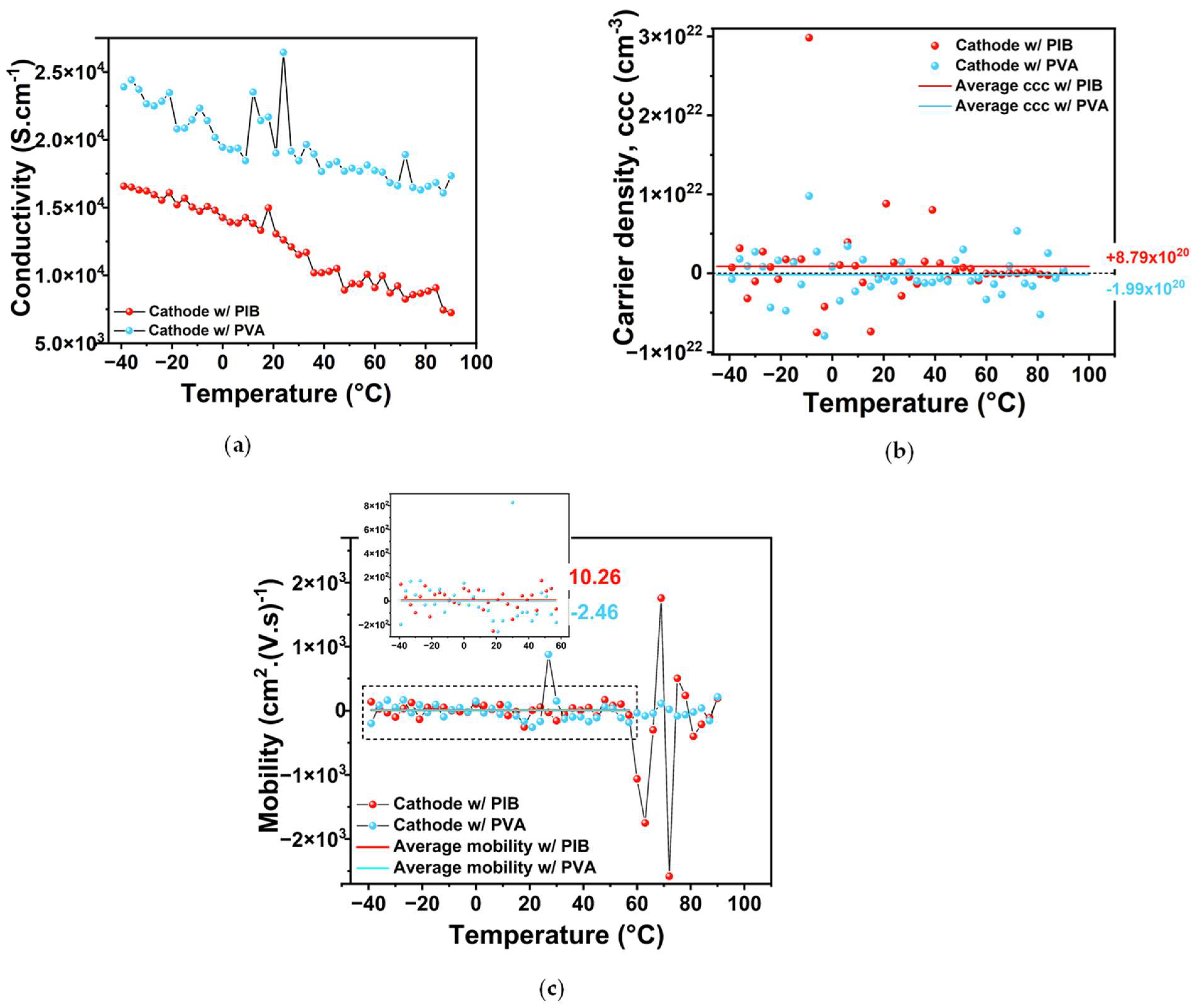
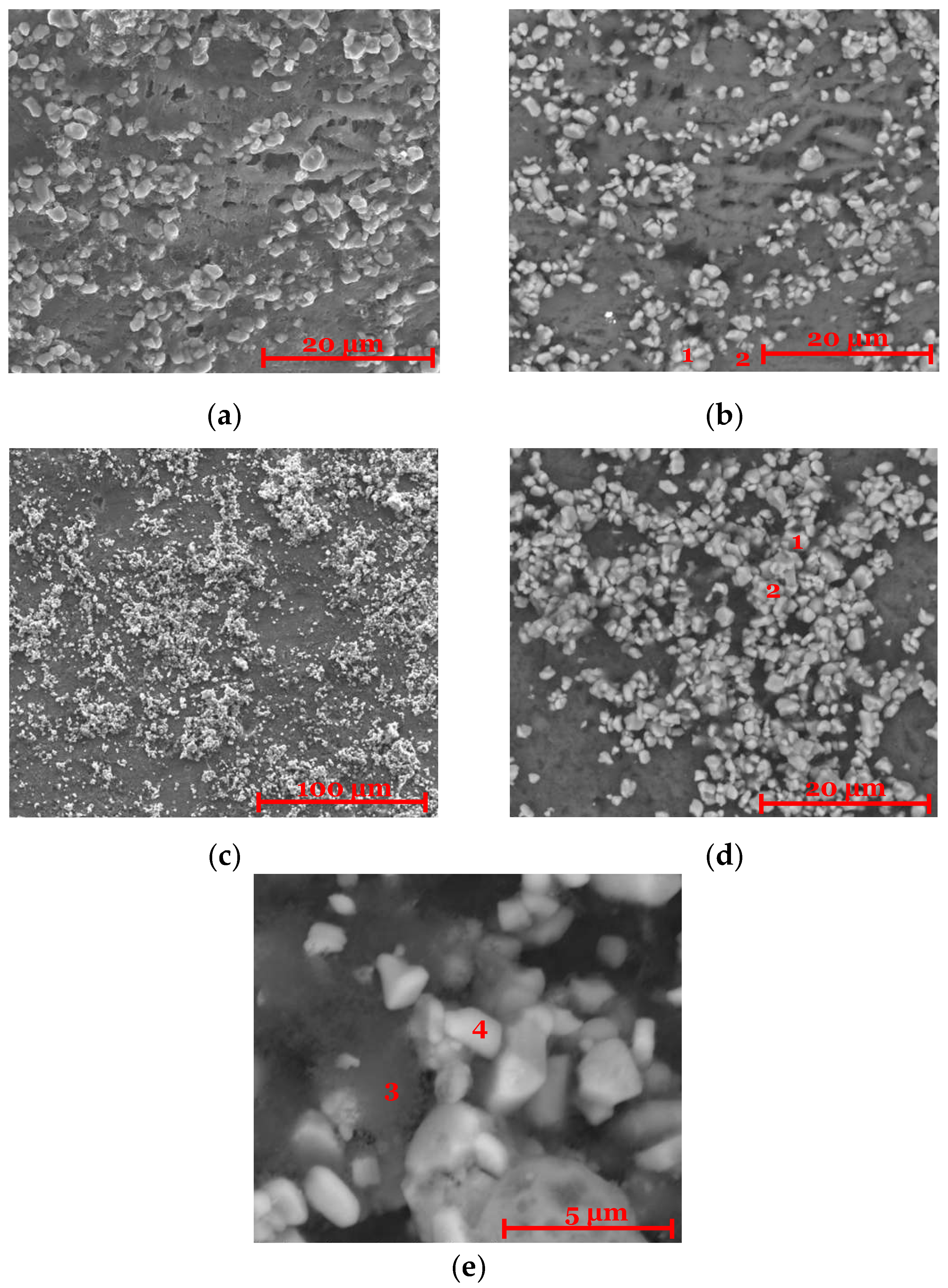
2.1. Cathode Characterization (SEM/EDX and Sheet Resistance/Hall Effect)

The microstructural analysis of the prepared cathode disks is presented in Figure 1. Figure 1a,b show the microstructure of the NMC955 (57%) + LPSCl (36%) + PIB (4%) + C65 (3%) composition. These images show the presence of an elastic matrix that effectively binds the cathode particles. The brighter regions, observed in Figure 1b and confirmed by elemental analysis (Table A1 and Table A2), correspond to the NMC955 active material, while the surrounding matrix consists of a mixture of LPSCl, binder, and conductive carbon. Figure 1c,d display the microstructure of the NMC955 (57%) + LPSCl (36%) + PVA (4%) + C65 (3%) composition. In this case, no elastic matrix is observed; however, the cathode remains highly homogeneous. As with the previous composition, the brighter particles correspond to the NMC955 active material, while the darker, more diffuse areas are attributed to the lighter LPSCl and binder mixture. It is highlighted that the radiation used are backscattered electrons. Elemental analysis (Table A1 and Table A2) confirms that all components are present in the expected stoichiometry. Both cathodes exhibit a uniform distribution of particles throughout the structure.
In both composite cathodes, NMC955 and C65 are the only intrinsically conductive components, while LPSCl exhibits semiconductor–insulator behavior and the binders (PIB or PVA) are electronic insulators. For effective battery operation, the cathode must display conductive behavior. Sheet resistance measurements reveal that both cathode compositions display an increase in resistance (a decrease in conductivity) with increasing temperature (Figure 2a), which is indicative of metallic or conductor behavior. This suggests that, despite the presence of semiconductor and insulator materials, the conductive network formed by NMC955 and C65 remains intact.
Charge carrier concentration was determined using Hall effect measurements conducted under a magnetic field of up to ±0.7 T, applied through two magnetic circuits. A Hall current of 3 mA was applied through the cathode sheets, and the Hall voltage (VH) and Hall coefficient (RH) were measured to calculate the charge carrier concentration (CCC), as detailed in Section 3. The polarity (positive or negative) of VH depends on whether the charge carriers are positive or negative.
As shown in Figure 2b, the PIB-based cathode exhibited an average carrier density of 8.79 × 1020 cm−3, associated with hole-type (h⁺, positive) carriers. In contrast, the PVA-based cathode showed an average carrier density of −1.99 × 1020 cm−3, indicating electron-type (e, negative) carriers (Figure 2b). The present number and polarity of average charge carriers indicate that the electrodes are degenerate semiconductors or heavily doped oxides, with partially metallic behavior. They are in the borderline between semiconductors and metallic conductors.
Mobility analysis (Figure 2c) reveals a transition region for the PIB-based cathode between 60 and 80 °C, characterized by a sudden increase in negative charge mobility followed by alternating peaks of positive and negative carrier mobility. The average charge mobility between −40 and 60 °C is 10.26 cm2·V−1·s−1 for the PIB-based cathode and −2.46 cm2·V−1·s−1 for the PVA-based cathode, showing once again that PIB and PVA binder-based cathodes are more prone to display positive and negative charge mobility, respectively, likely indicating that the PIB and PVA are, respectively, better cationic and electronic conductors. The change in charge mobility observed in the PIB-based cathode around 60–80 °C (Figure 2c) is likely due to thermal softening, which can change its mechanical properties. As PIB transitions into a viscoelastic state, conductive pathways may be compromised by weakening contact between the active materials. Above −70 °C, PIB is a supercooled liquid. Above ≈200 °C, depending on the type of PIB (for example, from its molecular weight), it melts.
The results obtained for conductivity and CCC for PIB are consistent with those reported in [18] for SBR binder-based NMC955 cathode (1.13 × 10²¹ h+ cm−3). The conductivity shows the same trend, decreasing with temperature, and the measured values are of the same order of magnitude. These findings reinforce the potential of NMC955 as a promising high-capacity material, particularly due to its compatibility with various alternative binders that are more sustainable than conventional options such as PVDF.

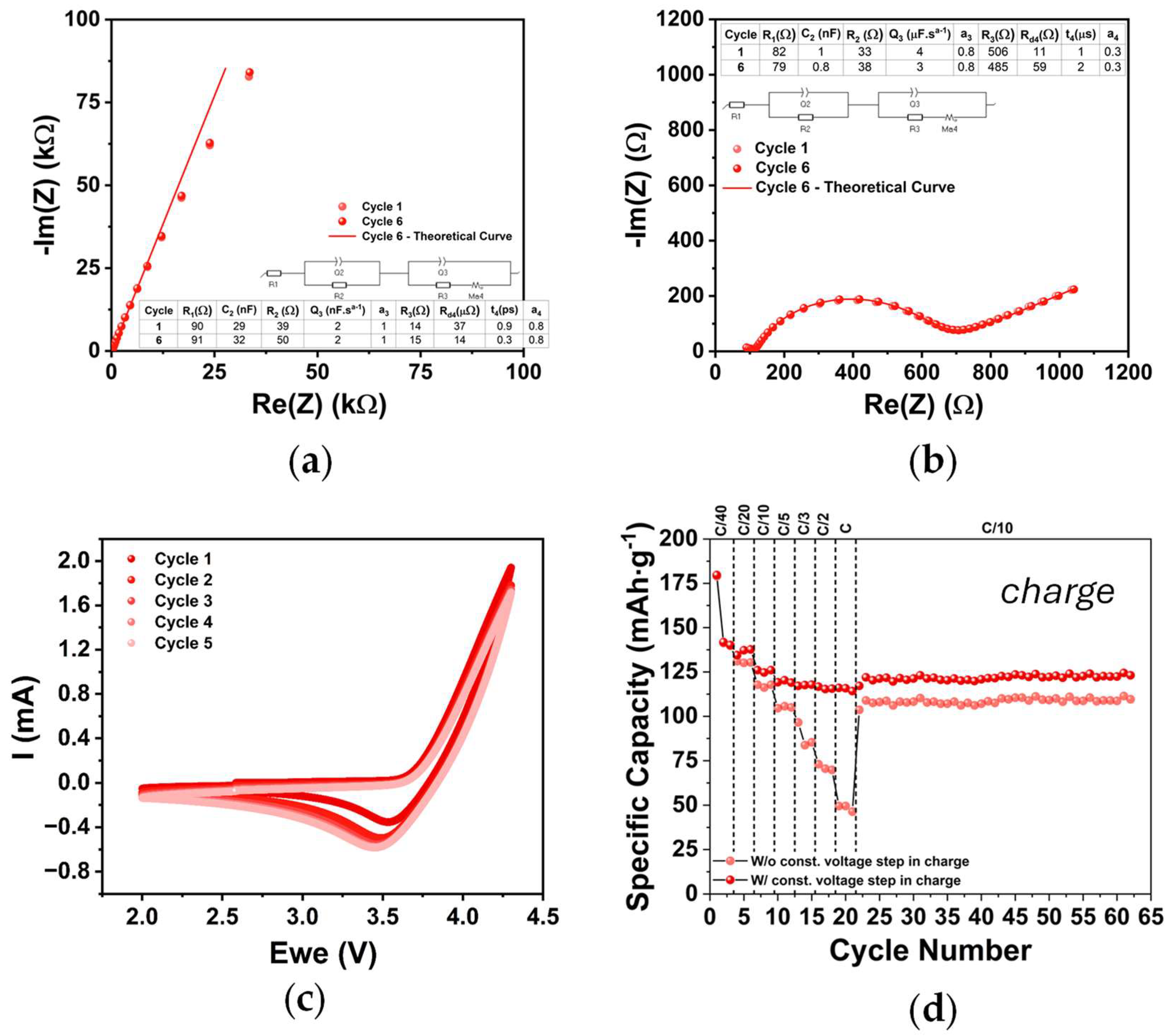
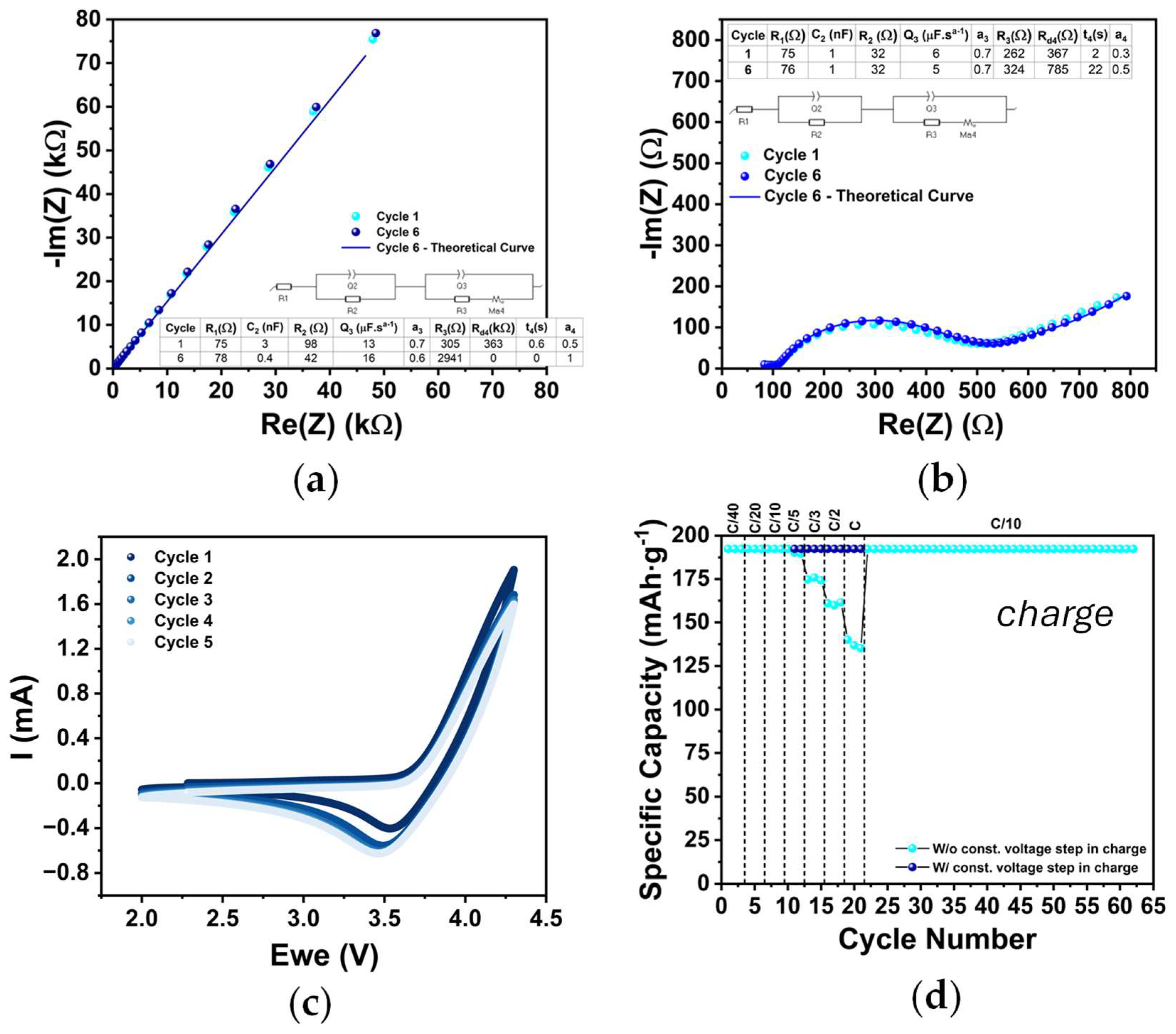
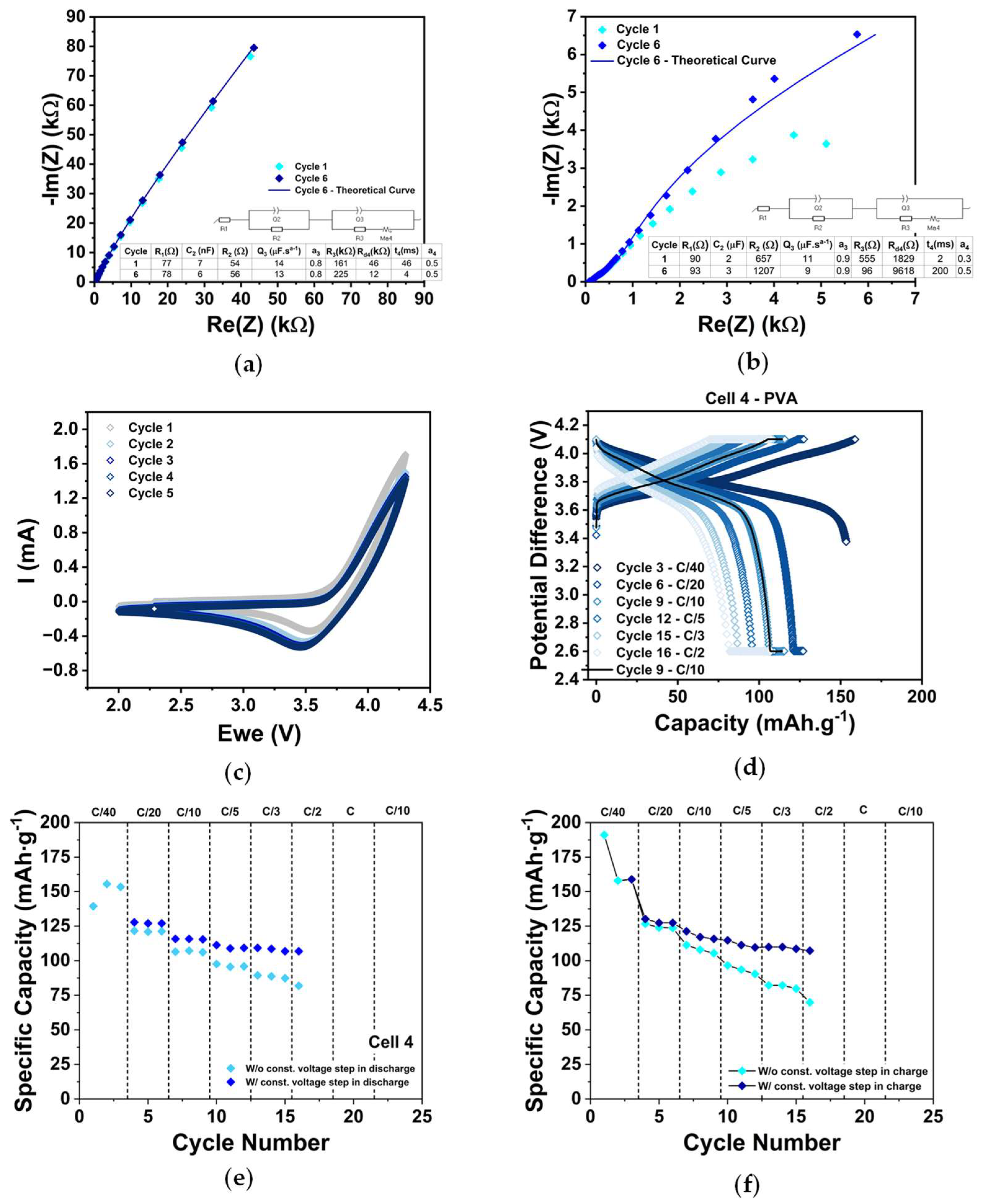
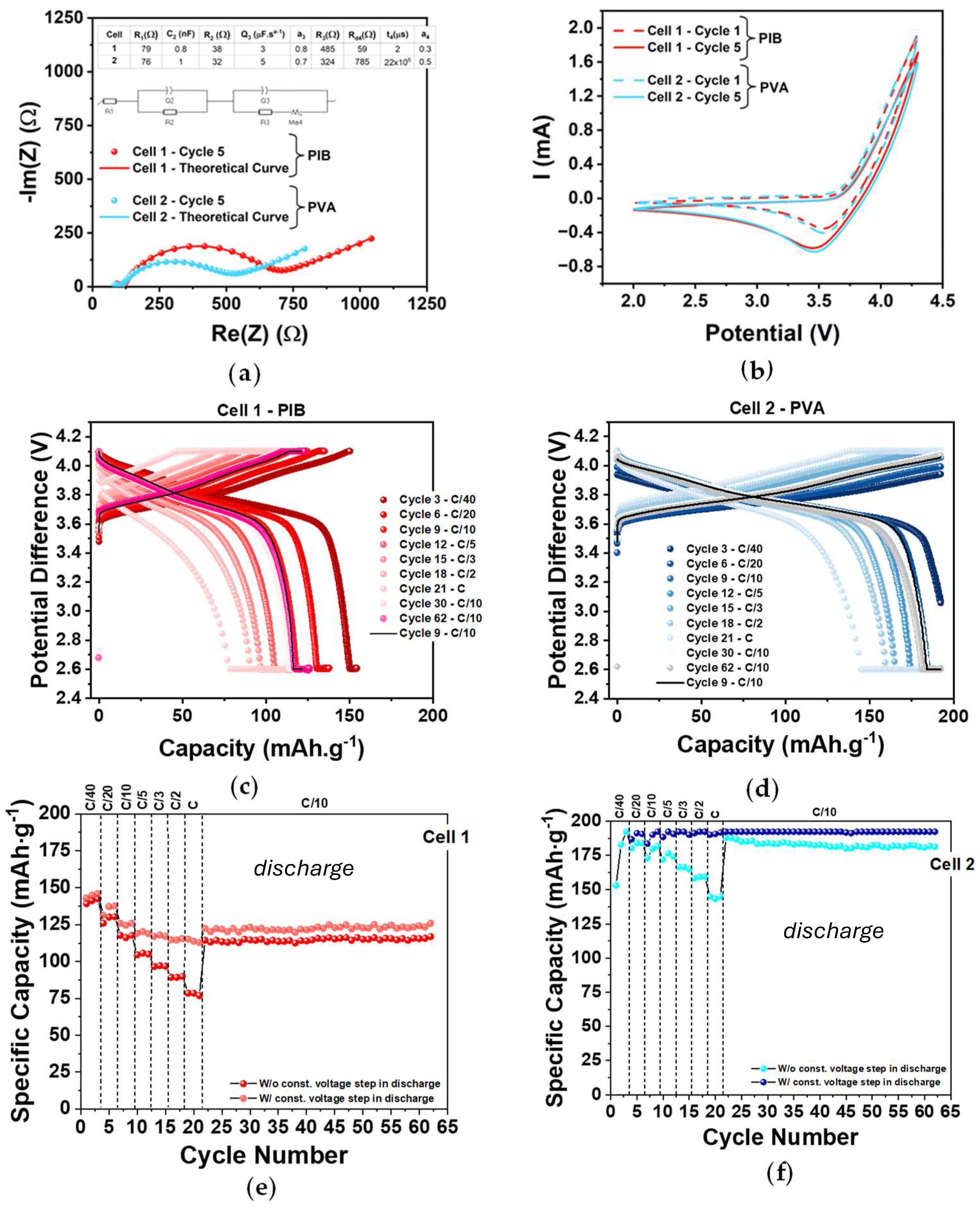
2.2. Cathode Electrochemical Characterization (PEIS, CV, and GCD)

All-solid-state coin cells were assembled with the obtained cathode disks, LPSCl as the electrolyte–separator and Li metal as the anode. A summary of all fabricated cells can be found in Table A1.
After assembly, cells underwent PEIS and CV tests. The equivalent circuit derived from the PEIS analysis was used to determine the ionic behavior of the system, with component values extracted accordingly (Figure 3a). R1, an ohmic resistance, corresponds to the conduction of the most mobile ionic species at high frequencies and is associated with interfacial contact resistance; ideally, it should approach zero. R2, representing the diameter of the first semicircle in the Nyquist plot, models bulk ionic transport through the electrolyte via ion hopping. This process is effectively represented by a resistor (R2) in parallel with a capacitor, capturing the dielectric behavior of the solid electrolyte in an “ideal” capacitor of thickness d. It does not account for the movement of the ions at the interfaces. In solid-state inorganic electrolytes, Li⁺ migration in one direction is accompanied by the movement of negatively charged vacancies in the opposite direction, influencing both electrodes simultaneously, and therefore the corresponding resistance is associated in parallel with the “ideal” capacitor. Interfacial processes, particularly those related to electrical double layer formation, are reflected in the elements Q3, R3, and Rd4. These elements represent non-ideal Li⁺ diffusion within the double-layer structure, mainly occurring at the positive electrode and limited to a narrow region with unknown thickness, usually of the order of angstrom.
This interpretation applies to both Cell 1 and Cell 2 (Figure 3a). In both cases, R1 and R2 exhibit low and comparable values, indicating similar bulk conductivity. A second semicircle is clearly visible in both spectra, signifying the formation of a double layer at the electrode–electrolyte interface. Notably, R3 is higher in the PIB cell, suggesting increased resistance to interfacial charge transfer or Li⁺ accumulation. Additionally, both PEIS spectra exhibit a linear low-frequency tail, characteristic of diffusion-controlled processes, confirming the presence of diffusion behavior.
The CVs show a reduction peak at approximately 3.5 V while discharging the cell (Figure 3b). The current response rises above 4.1 V, suggesting a shift in charge carrier origin from e to h+ (with possible loss of O2−), showcasing the importance of not charging beyond this cut-off voltage. The used voltage window was verified in already published theoretical simulations [18]. All CV curves are directly comparable since the active area is the same for all cells (≈0.5 cm2) and the mass of active material is similar (Table A1). For both cathode formulations the maximum current is situated at approximately 1.8 mA, showing very similar behavior.
All cells were subjected to electrochemical cycling between 2.6 and 4.1 V at various C-rates (C/40, C/20, C/10, C/5, C/3, C/2, and C), Figure 3c,d. Tests were conducted at room temperature without the application of external pressure. To prevent structural degradation of the NMC955 material due to complete lithium extraction, only approximately 70% of the lithium ions were targeted for de-lithiation. This limitation reduces the theoretical specific capacity of the NMC955 cathode to an estimated 192 mAh·g−1.
The electrochemical performance of the best-performing cell for each binder formulation is presented in Figure 3c,d. For the PIB-based cell, a maximum capacity of approximately 145 mAh·g−1 was achieved at C/40, with capacity decreasing as the C-rate increased (Figure 3e). The theoretical capacity was not reached at any point during cycling. In contrast, the PVA-based cell reached the theoretical capacity multiple times, even without requiring a constant voltage step, for lower C-rates. For C/40, the theoretical capacity was achieved before reaching the upper cut-off voltage of 4.1 V. Although the capacity decreased with increasing C-rate, the cell maintained a minimum capacity of 150 mAh·g−1 at 1C, and with the addition of a CV step, it was able to reach the theoretical capacity (Figure 3f). Furthermore, upon repeating the C/10 rate, the PVA-based binder cell demonstrated a higher capacity than at the beginning of cycling, suggesting ongoing improvement in electrochemical behavior (Figure 3f). Additional experimental data supporting these conclusions is presented in the Figure A1 and Figure A2. Figure A3 and Figure A4 present experimental results for Cell 3 and Cell 4 (Table A1) with the same cathode formulations, showing comparable performance to the results reported in the main text. The electrochemical performance achieved shows that both cathodes can be used to fabricate stable, long-lasting cells with promising discharge capacities.

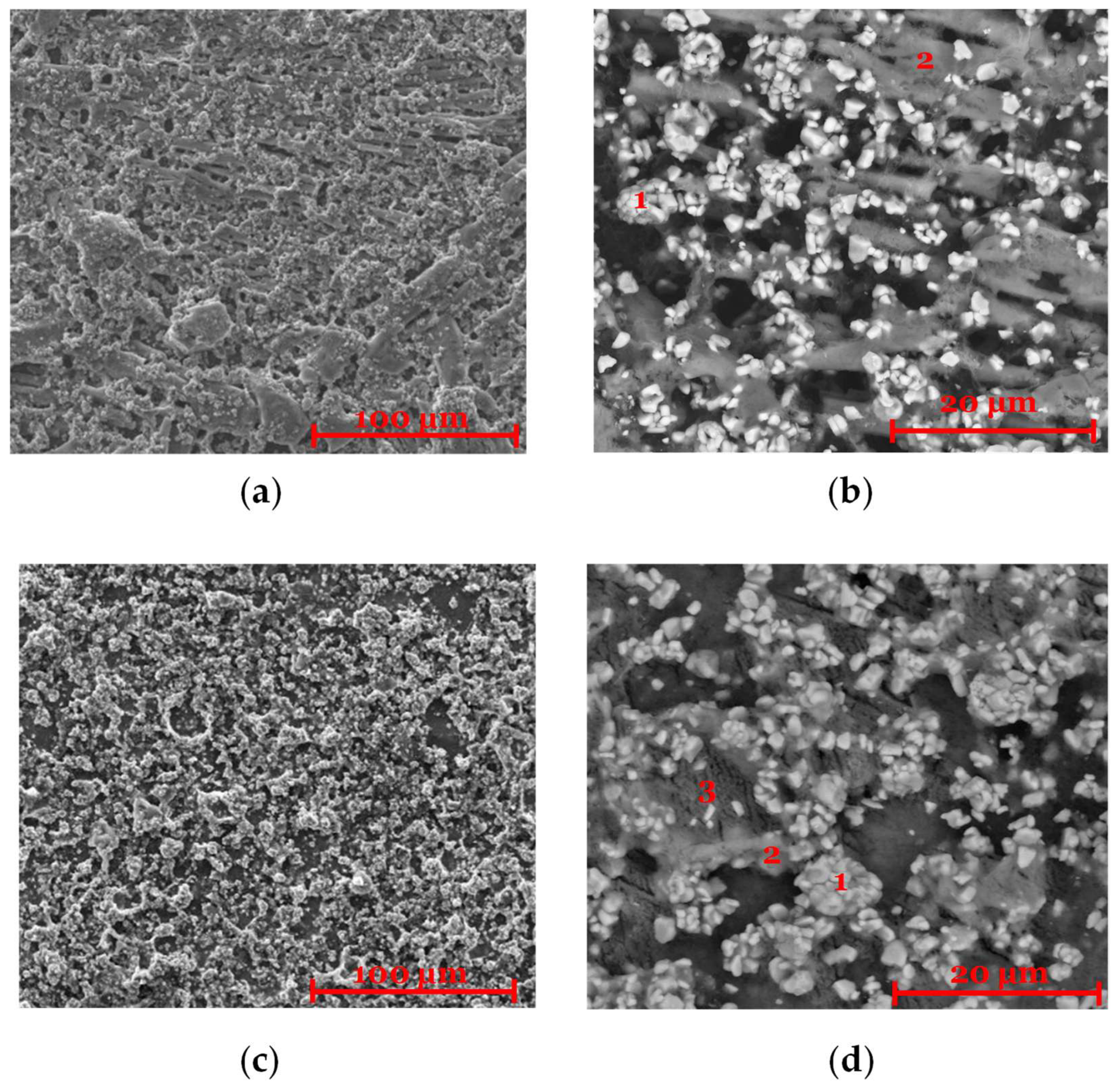
2.3. Post-Mortem Characterization (SEM/EDX)

Once the GCD tests were finished, cells were opened inside the glove box, and the cathodes were analyzed using post-mortem SEM/EDX. The performance of the cells selected for this analysis is shown in Figure A3 and Figure A4. In the PIB-based cathode, remnants of the elastic matrix were still visible (Figure 4a,b). A decrease in sulfur content compared to the initial composition (Table A2 and Table A4) was observed, consistent with the formation of sulfates as reported in [18]. NMC955 particles remained detectable, but a reduction in oxygen content was noted (Table A2 and Table A4), likely due to oxygen release during charging. This observation is supported by the CV data, which showed increased current near 4.1 V, suggesting the occurrence of competing side reactions.
For the PVA-based cathode (Figure 4c–e), a similar reduction in oxygen content was observed (Table A3 and Table A5). While Figure 4c seems to show fewer deposited particles compared to Figure 1c, this comparison should be interpreted with caution. The more difficult demolding process for the PVA sample may have damaged the surface, potentially affecting the observed microstructure and the quality of the analysis.

3. Materials and Methods

Solubility tests were conducted to assess the viability of pairing PVA [HiMedia, Poly (vinyl alcohol) cold water soluble] and PIB (Sigma Aldrich, St. Louis, MO, USA, BM, USA Polyisobutylene) with toluene (Honeywell, purity ≥ 99.7%). A fixed mass of PVA was added to 5 mL of toluene and stirred magnetically at 250 rpm for 24 h. Experiments were conducted at both room temperature and 40 °C. The results indicated that PVA was miscible with toluene at the elevated temperature of 40 °C, even having higher polarity. To enable a direct comparison between PVA and PIB as binder materials, cathode synthesis was performed at 40 °C for both materials.
The composite cathode material was prepared using a mixture of 57% NMC 955 (Huayou New Energy Technology, Quzhou, China), 36% Li6PS5Cl (NEI Corporation, Somerset, NJ, USA), 3% C65 (TIMCAL graphite and carbon super C65), and 4% binder: PVA or PIB. The used solvent was toluene (Honeywell International Inc., Charlotte, NC, USA, purity ≥ 99.7%), and the target for the total mass of the cathode was 1 g.
The binder was initially mixed with 2 mL of toluene and magnetically stirred. The active material and conductive agent were then added together, followed lastly by the solid electrolyte powder. Each mixing step was performed for 24 h at 250 rpm at 40 °C. To ensure a proper mixing and a homogeneous deposition, an additional 0.5 mL of toluene was added with the electrolyte at the last stirring stage. Once a homogeneous slurry was obtained, it was deposited with a thickness of 250 µm onto pre-heated aluminum foil coated with carbon (MSE Supplies LLC, Tucson, AZ, USA) of 15 µm thickness and left to dry overnight. The dried cathode film was then cut into 10 mm diameter disks using a TMAX-CN cutter. All procedures were conducted inside a GS Glovebox (O2 < 1 ppm, H2O < 1 ppm).
A scanning electron microscope (SEM) (FEI QUANTA 400 FEG ESEM, Hillsboro, OH, USA) was used for microstructural analysis. Chemical composition was determined using an EDAX Genesis X4M energy-dispersive X-ray spectrometer (EDX) (Thermo Scientific, Waltham, MA, USA). Observations were carried out at an accelerating voltage of 15 kV, with a spot size between 3 and 5 and a working distance of 10 µm. The microstructure was observed with magnifications ranging from 20× to 20,000× using a backscattered electron detector (Thermo Scientific, Waltham, MA, USA).
Hall effect measurements were conducted using the Linseis HCS 1 system, equipped with two neodymium magnetic circuits on a movable sled. Samples were mounted with edge contacts, and a perpendicular magnetic field of ±0.7 and 0 T was applied. A constant current of 3 mA was applied to the samples (NMC955 cathodes with PIB or PVA), and the resulting Hall voltage ( V H ), generated orthogonal to both the current ( I ) and magnetic field ( B ), was precisely measured with high sensitivity from −40 to 90 °C. Each temperature is equilibrated for a heating/cooling rate of ≈0.5 °C.min−1. The Hall coefficient ( R H ) and charge carrier concentration ( n ) can be calculated using the equations R H = V H · d I B , where d is the sample thickness, and n = 1 e · R H .
Sheet resistance analysis was performed on the electrodes using the Van der Pauw method with four collinear contacts. Current and voltage were applied across different contact pairs in multiple configurations to ensure accuracy. Sheet resistance R S was determined using the formula R S = V I · f , with correction factor f , and the Van der Pauw relation e π R s 1 / R s + e π R s 2 / R s = 1 . All tests were performed under controlled conditions, with the chamber evacuated to 10−2 bar and flushed with nitrogen gas (4–5 L/min) to reduce noise, temperature fluctuations, and unwanted reactions.
To assemble the cells, 100 mg of Li6PS5Cl were pressed onto the cathode disk for 90 s at 1 ton, using a mold with a 10 mm diameter and the SPECAC press machine, and forming a bilayer. The coin cells were fabricated by stacking the anode on top of the SSE sheet of the bilayer, followed by a spacer and a spring. The used anode material was Li metal with a thickness of 200 μm and an 8 mm diameter. The cells were closed using a pressure-controlled electric crimper for coin cells MSK-160E. The capacities of the cathodes were calculated based on the active area of the cathode, which is constrained by the size of the anode (d ≈ 8 mm), and considering the theoretical capacity of 192 mAh.g−1. The anode was made smaller than the cathode to avoid short circuits by possible contact at the disk’s edge. Three types of electrochemical tests were performed to evaluate the fabricated cells. Potentiostatic electrochemical impedance spectroscopy (PEIS) tests were performed to evaluate the internal impedance. Cyclic voltammetry (CV) tests were performed to determine the capacity of the obtained cell. Both were performed using a Biologic VMP-300 potentiostat (Seyssinet-Pariset, France). Lastly, galvanostatic charge–discharge (GCD) was implemented to evaluate the cyclability and behavior of cells at different C-rates. The latter were performed in a Neware-CT-4008Tn-5V-20mA battery tester (Montclair, CA, USA) with 2.6 and 4.1 V cut-off voltages.

4. Conclusions

This work demonstrates a scalable and cost-effective fabrication method for an Li0/Li6PS5Cl/NMC955 all-solid-state half-cell. The high specific capacities achieved are attributed to the high-Ni, low-Co stoichiometry of NMC955, which enhances energy density. Both binders, PVA and PIB, emerge as viable alternatives to the conventional PVDF. PVA shows itself as the best-performing binder, which is likely associated with an average excess of negative charges ( e ¯ ) of 2.4 mAh.g−1, corresponding with higher electronic and ionic conductivity, while the PIB shows a correspondent excess of positive charges ( h + or L i + in the cathode) of 10.7 mAh.g−1, considering the densities of the cathodes of 3.64 g.cm−3 (PIB-based) and 3.73 g.cm−3 (PVA-based). PVA is the better choice for ionic conduction. Neither PVA nor PIB is naturally good at electronic conduction, but PVA is more efficient when composited with conductive fillers (e.g., carbon, graphene) to form mixed-conduction systems.
Cathodes synthesized with the proposed method deliver stable and long-lasting performance, achieving capacities of 145 mAh·g−1, at C/40 in the case of the PIB formulation and 192 mAh.g−1 at all the tested C-rates for the PVA formulation. Cells maintained a high-rate capability at C/10 after being tested from C/40 to 1C. Electrochemical testing, alongside SEM/EDX characterization and Hall effect/sheet resistance measurements, highlights the role of cathode design in determining overall cell performance and cycle life.

Author Contributions

Conceptualization, J.M.P., B.M.G. and M.H.B.; methodology, J.M.P., B.M.G. and M.C.B.; validation, M.H.B.; formal analysis, J.M.P., B.M.G. and M.H.B.; investigation, Pinheiro, J.M.P., B.M.G. and M.C.B.; resources, M.H.B.; data curation, J.M.P., B.M.G. and M.C.B.; writing—original draft preparation, J.M.P., B.M.G. and M.H.B.; writing—review and editing, J.M.P. and M.H.B.; visualization, J.M.P., B.M.G. and M.H.B.; supervision, M.H.B.; project administration, M.H.B.; funding acquisition, M.H.B. All authors have read and agreed to the published version of the manuscript.

Funding

B.M.G., M.C.B. and M.H.B acknowledge the European Union’s Horizon Europe Research and Innovation Programme under grant agreement No. 101069686 (PULSELiON). Views and opinions expressed are those of the author(s) only and do not necessarily reflect those of the European Union. This project benefited from FCT UIDP/50022/2020 Emerging Technologies–LAETA. J.M.P. acknowledges the scholarship funded by the Engineering Faculty of the University of Porto.

Data Availability Statement

The data will be made available upon reasonable request.

Conflicts of Interest

The authors declare no conflicts of interest. The funders had no role in the design of the study; in the collection, analyses, or interpretation of data; in the writing of the manuscript; or in the decision to publish the results.

Abbreviations

The following abbreviations are used in this manuscript:
ASSBall-solid-state battery
CAMcathode active material
CVcyclic voltammetry
EDXenergy-dispersive X-ray spectroscopy
EVelectric vehicle
GCDgalvanostatic charge and discharge
LEliquid electrolyte
LIBlithium-ion battery
LPSClLi6PS5Cl
NMCLiNixMnyCo1-x-yO2
PEISpotentiostatic electrochemical impedance spectroscopy
PIBpolyisobutene
PVApolyvinyl acetate
PVDFpolyvinylidene fluoride
SEMscanning electron microscope
SSEsolid-state electrolyte

Appendix A

Table A1. Summary table of the cells reported in the paper.
Cell IDBinderMass of NMC 955 (mg) Areal Capacity (mAhcm−2)Correspondent
Figures
Cell 1PIB4380.168Figure 1a,b, Figure 2, Figure 3a–c,e and Figure 4a,b
Cell 2PVA1820.07Figure 1c,d, Figure 2, Figure 3a,b,d,f and Figure 4c–e
Cell 3PIB4380.168Figure A3
Cell 4PVA2920.112Figure A4
Table A2. EDX data for the PIB-based cathode (57% NMC955 + 36% Li6PS5Cl + 3% C65 + 4% PIB) shown in Figure 1.
At %
CONiMnCoPSCl
14.2954.2434.541.701.490.292.610.84
212.1528.472.150.140.288.4541.996.37
Table A3. EDX data for the PVA-based cathode (57% NMC955 + 36% Li6PS5Cl + 3% C65 + 4% PVA) shown in Figure 1.
At %
CONiMnCoPSCl
15.0044.6738.521.932.010.906.220.75
28.783.0066.911.332.202.6113.231.94
313.1919.152.650.440.507.6647.409.01
Table A4. Post-mortem EDX data for the PIB-based cathode (57% NMC955 + 36% Li6PS5Cl + 3% C65 + 4% PIB) shown in Figure 4.
At %
CONiMnCoPSCl
19.0147.6937.681.691.870.331.400.33
224.2825.871.120.220.268.1033.826.33
Table A5. Post-mortem EDX data for the PVA-based cathode (57% NMC955 + 36% Li6PS5Cl + 3% C65 + 4% PVA) shown in Figure 4.
At %
CONiMnCoPSCl
151.2925.6017.370.881.480.232.900.25
27.2252.5334.181.551.810.122.430.16
371.1411.9811.560.670.790.433.000.43
413.6850.3430.151.471.510.382.170.30
Figure A1. Electrochemical characterization of Cell 1 (PIB-based): (a) PEIS analysis before CV; (b) PEIS analysis after CV; (c) CV results, all cycles; (d) specific charge capacity as a function of number of cycles.
Molecules 30 02974 g0a1
Figure A2. Electrochemical characterization of Cell 2 (PVA-based): (a) PEIS analysis before CV; (b) PEIS analysis after CV; (c) CV results, all cycles; (d) specific charge capacity as a function of number of cycles.
Molecules 30 02974 g0a2
Figure A3. Electrochemical characterization of Cell 3: (a) PEIS analysis before CV; (b) PEIS analysis after CV; (c) CV results, all cycles; (d) GCD results, the third and last cycle at each C-rate is plotted; (e) specific discharge capacity as a function of cycle number; (f) specific charge capacity as a function of cycle number.
Molecules 30 02974 g0a3
Figure A4. Electrochemical characterization of Cell 4: (a) PEIS analysis before CV; (b) PEIS analysis after CV; (c) CV results, all cycles; (d) GCD results, the third and last cycle at each C-rate is plotted; (e) specific discharge capacity as a function of cycle number; (f) specific charge capacity as a function of cycle number.
Molecules 30 02974 g0a4

References

  1. Markets and Markets. Lithium-Ion Battery Market Size, Share and Growth Analysis. 2023. Available online: https://www.marketsandmarkets.com/Market-Reports/lithium-ion-battery-market-49714593.html?gad_source=1&gclid=Cj0KCQjw1um-BhDtARIsABjU5x4h8ruL5crN1XqYbete5aC-1FNAa1kVcqh6W4N1yiFgMxRgJaleLmQaAuEDEALw_wcB (accessed on 24 March 2025).
  2. Li, W.; Song, B.; Manthiram, A. High-voltage positive electrode materials for lithium-ion batteries. Chem. Soc. Rev. 2017, 46, 3006–3059. [Google Scholar] [CrossRef] [PubMed]
  3. Wen, J.; Yu, Y.; Chen, C. A review on lithium-ion batteries safety issues: Existing problems and possible solutions. Mater. Express 2012, 2, 197–212. [Google Scholar] [CrossRef]
  4. Manthiram, A. A reflection on lithium-ion battery cathode chemistry. Nat. Commun. 2020, 11, 1550. [Google Scholar] [CrossRef] [PubMed]
  5. International Energy Agency. Global EV Outlook 2024 Moving Towards Increased Affordability. 2024. Available online: https://www.iea.org (accessed on 14 July 2025).
  6. Celadon, A.; Sun, H.; Sun, S.; Zhang, G. Batteries for electric vehicles: Technical advancements, environmental challenges, and market perspectives. SusMat 2024, 4, e234. [Google Scholar] [CrossRef]
  7. Nkulu, C.B.L.; Casas, L.; Haufroid, V.; De Putter, T.; Saenen, N.D.; Kayembe-Kitenge, T.; Obadia, P.M.; Mukoma, D.K.W.; Ilunga, J.-M.L.; Nawrot, T.S.; et al. Sustainability of artisanal mining of cobalt in DR Congo. Nat. Sustain. 2018, 1, 495–504. [Google Scholar] [CrossRef] [PubMed]
  8. Manthiram, A.; Yu, X.; Wang, S. Lithium battery chemistries enabled by solid-state electrolytes. Nat. Rev. Mater. 2017, 2, 16103. [Google Scholar] [CrossRef]
  9. Zhao, S.; Jiang, W.; Zhu, X.; Ling, M.; Liang, C. Understanding the synthesis of inorganic solid-state electrolytes for Li ion batteries: Features and progress. Sustain. Mater. Technol. 2020, 33, e40091. [Google Scholar] [CrossRef]
  10. Huo, S.; Sheng, L.; Xue, W.; Wang, L.; Xu, H.; Zhang, H.; He, X. Challenges of polymer electrolyte with wide electrochemical window for high energy solid-state lithium batteries. InfoMat 2023, 5, e12394. [Google Scholar] [CrossRef]
  11. Phillip, N.D.; Westover, A.S.; Daniel, C.; Veith, G.M. Structural Degradation of High Voltage Lithium Nickel Manganese Cobalt Oxide (NMC) Cathodes in Solid-State Batteries and Implications for Next Generation Energy Storage. ACS Appl. Energy Mater. 2020, 3, 1768–1774. [Google Scholar] [CrossRef]
  12. Bielefeld, A.; Weber, D.A.; Janek, J. Microstructural Modeling of Composite Cathodes for All-Solid-State Batteries. J. Phys. Chem. C 2019, 123, 1626–1634. [Google Scholar] [CrossRef]
  13. Han, S.C.; Ali, M.; Kim, Y.J.; Park, J.; Lee, Y.-J.; Park, J.-W.; Park, H.; Park, G.; Lee, E.; Kim, B.G.; et al. Unraveling electrochemo-mechanical aspects of core–shell composite cathode for sulfide based all-solid-state batteries. J. Mater. Chem. A 2024, 12, 24896–24905. [Google Scholar] [CrossRef]
  14. Singer, C.; Schmalzbauer, S.; Daub, R. Influence of the slurry composition on thin-film components for the wet coating process of sulfide-based all-solid-state batteries. J. Energy Storage 2023, 68, 107703. [Google Scholar] [CrossRef]
  15. PFAS Restriction Proposal RECHARGE Statement for 2 nd Call for Evidence-October 2021, n.d. Available online: https://rechargebatteries.org/wp-content/uploads/2022/09/Call-for-Evidence_RECHARGE-_-PFAS-restriction-V1.pdf (accessed on 24 March 2025).
  16. Rolandi, A.C.; de Meatza, I.; Casado, N.; Forsyth, M.; Mecerreyes, D.; Pozo-Gonzalo, C. Unlocking sustainable power: Advances in aqueous processing and water-soluble binders for NMC cathodes in high-voltage Li-ion batteries. RSC Sustain. 2024, 2, 2125–2149. [Google Scholar] [CrossRef]
  17. Nikodimos, Y.; Huang, C.J.; Taklu, B.W.; Su, W.N.; Hwang, B.J. Chemical stability of sulfide solid-state electrolytes: Stability toward humid air and compatibility with solvents and binders. Energy Environ. Sci. 2022, 15, 991–1033. [Google Scholar] [CrossRef]
  18. Gomes, B.M.; Baptista, M.C.; Orue, A.; Dhrubajyoti, B.; Terlicka, S.; Sjövall, P.; Zamperlin, N.; Fonseca, C.; Smajic, J.; Kekkonen, V.; et al. All-solid-state lithium batteries with NMC955 cathodes: PVDF-free formulation with SBR and capacity recovery insights. Energy Mater. 2025, 5, 500091. [Google Scholar] [CrossRef]
Figure 1. SEM/EDX acquired with a backscattered electron detector. (a,b) Cathode with composition 57% NMC955 + 36% Li6PS5Cl + 3% C65 + 4% PIB observed with 1000× and 5000× magnification. (c,d) Cathode with composition 57% NMC955 + 36% Li6PS5Cl + 3% C65 + 4% PVA observed with 1000× and 5000× magnification. Note: zones 1 and 2 in (b) and 1, 2, and 3 in (d) are analyzed in Table A2 and Table A3, respectively.
Molecules 30 02974 g001
Figure 2. Experimental results from sheet resistance/Hall effect measurements: (a) Conductivity as a function of temperature—the obtained behavior is that of a typical metal; (b) charge carrier density as a function of temperature: positive in the cathode synthesized using PIB and negative for the cathode containing PVA; (c) charge carrier mobility coefficient as a function of temperature.
Molecules 30 02974 g002
Figure 3. Experimental results from electrochemical characterization: (a) PEIS analysis—both cells were modeled using the same equivalent circuit. The presented cycle is the last one before CV; (b) CV diagrams from each cell, cycles 1 and 5, are presented, displaying a stable behavior from start to finish of the test; (c) GCD test performed on Cell 1 (PIB binder), the third and last cycle for each C-rate is plotted; (d) GCD test performed on Cell 2 (PVA binder), the third and last cycle for each C-rate is plotted; (e) specific discharge capacity as a function of number of cycles from Cell 1 (PIB binder); (f) specific discharge capacity as a function of number of cycles from Cell 2 (PVA binder).
Molecules 30 02974 g003
Figure 4. Cathode characterization. Images were acquired with SEM/EDX and a backscattered electron detector. (a,b) Cathode with composition 57% NMC955 + 36% Li6PS5Cl + 3% C65 + 4% PIB observed with 5000× magnification; (ce) cathode with composition 57% NMC955 + 36% Li6PS5Cl + 3% C65 + 4% PVA observed with 1000×, 5000×, and 20,000× magnification. Note: zones 1 and 2 in (b), 1 and 2 in (d), and 3 and 4 in (e) are analyzed in Table A4 and Table A5.
Molecules 30 02974 g004
Disclaimer/Publisher’s Note: The statements, opinions and data contained in all publications are solely those of the individual author(s) and contributor(s) and not of MDPI and/or the editor(s). MDPI and/or the editor(s) disclaim responsibility for any injury to people or property resulting from any ideas, methods, instructions or products referred to in the content.

