
A Spectral Method for Rapidly Determining the Linear Birefringence of Thin Polymer Films


Abstract
1. Introduction
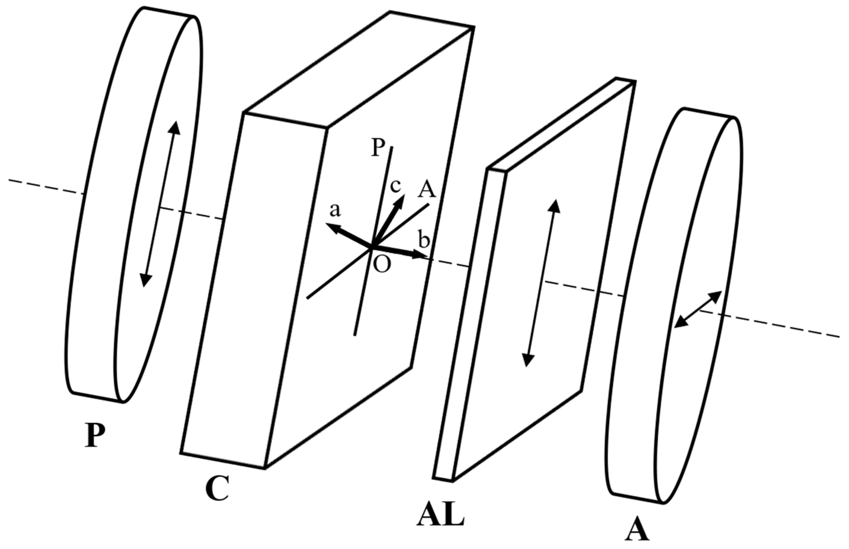
2. Experimental Setup
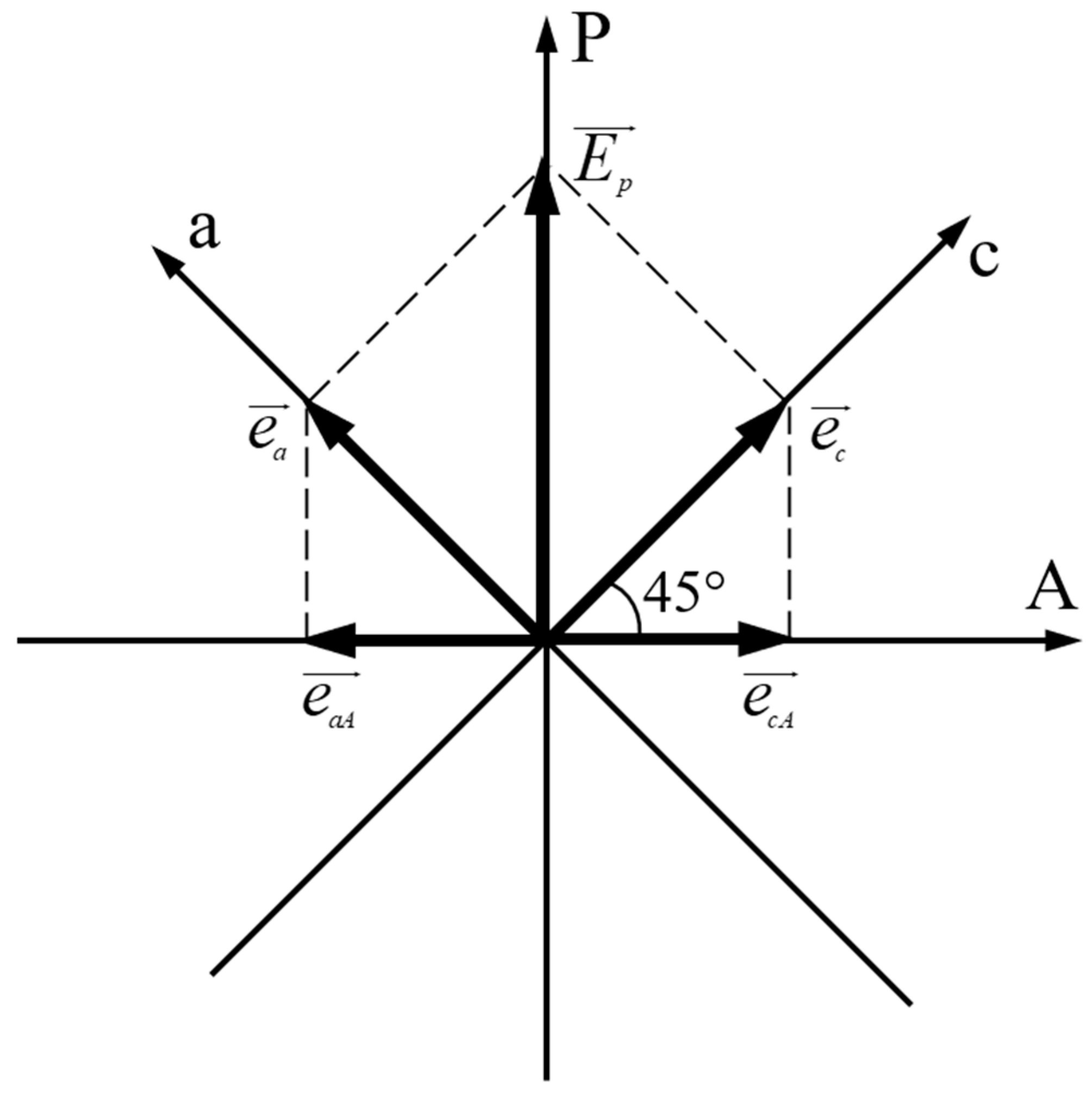
3. Theoretical Notions
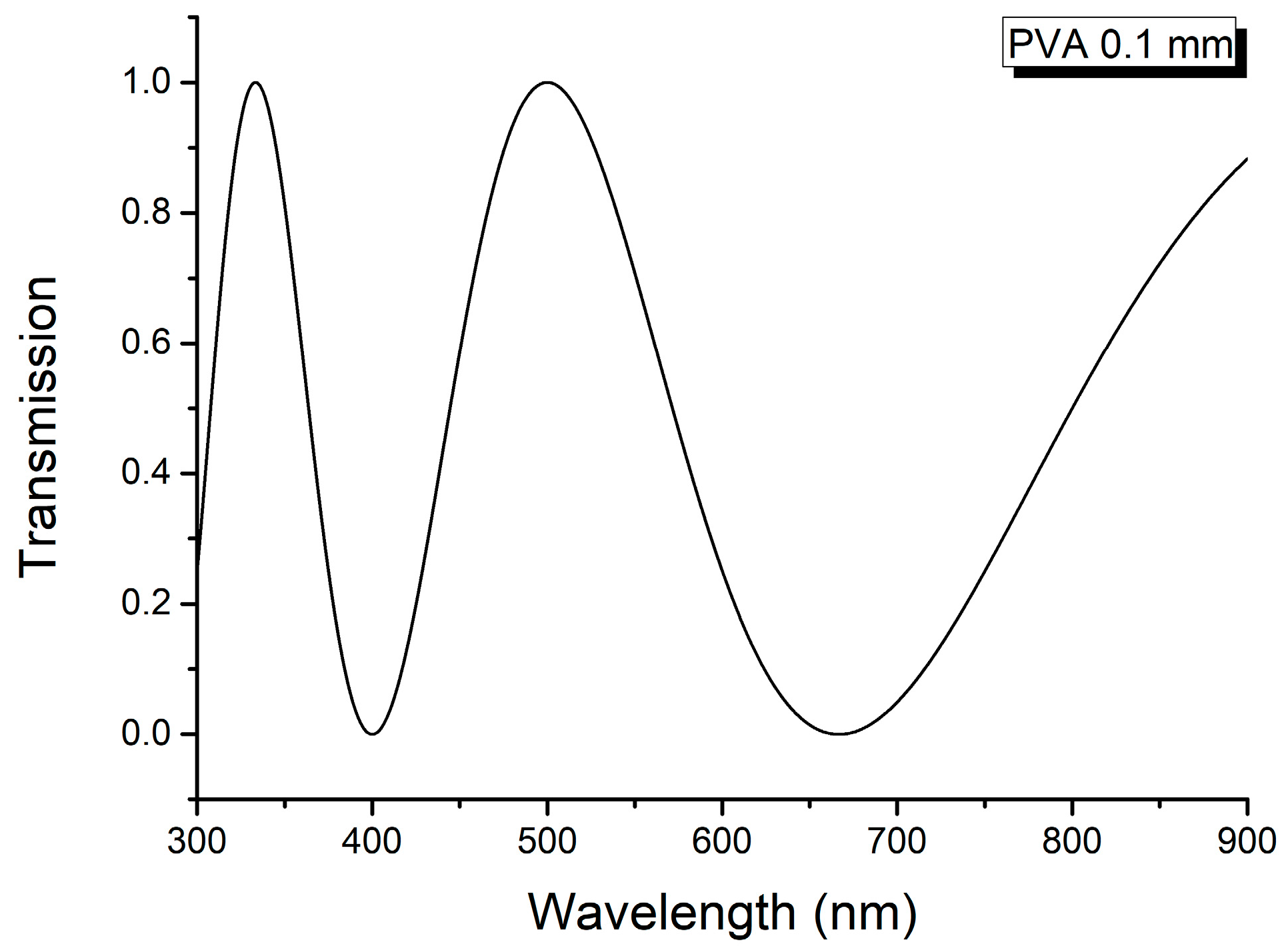
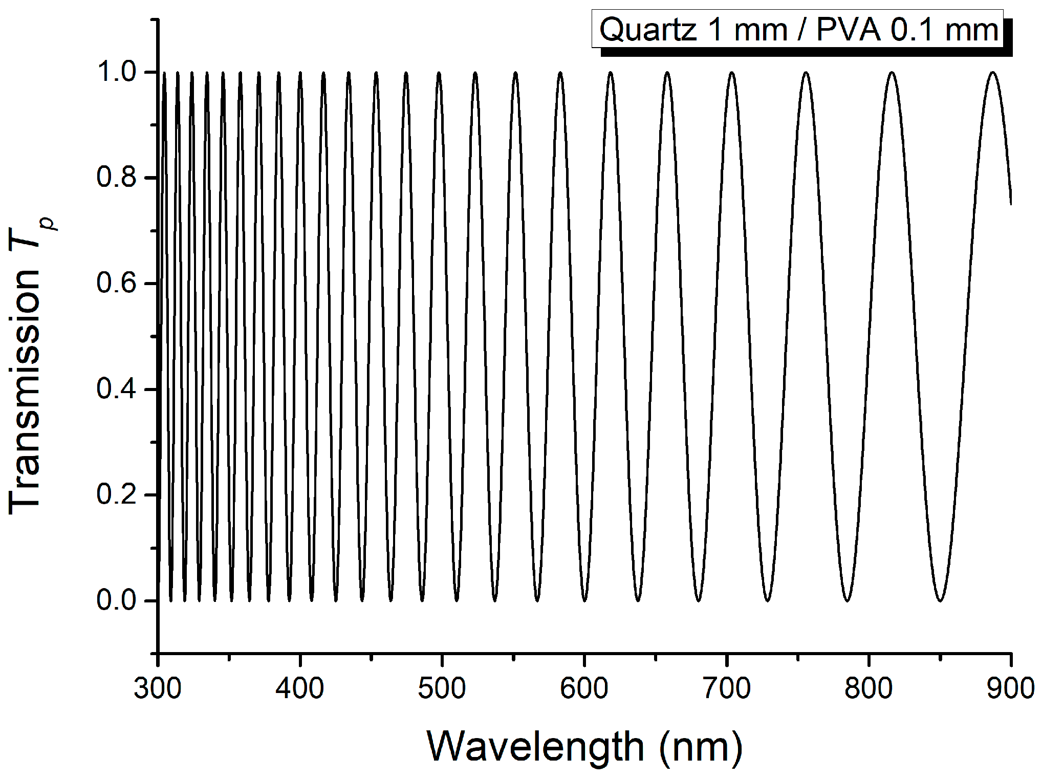
4. Results and Discussion
5. Conclusions
Author Contributions
Funding
Institutional Review Board Statement
Informed Consent Statement
Data Availability Statement
Conflicts of Interest
References
- Dorohoi, D.O.; Postolache, M.; Nechifor, C.D.; Dimitriu, D.G.; Albu, R.M.; Stoica, I.; Barzic, A.I. Review on optical methods used to characterize the linear birefringence of polymer materials for various applications. Molecules 2023, 28, 2955. [Google Scholar] [CrossRef]
- Postolache, M.; Ivan, L.M.; Puica-Melniciuc, N.; Dimitriu, D.G.; Dorohoi, D.O. Birefringence of binary liquid crystalline mixtures of MBBA and PPMAECOBA in TCM, interferometric assessment. Mol. Cryst. Liq. Cryst. 2020, 698, 78–86. [Google Scholar] [CrossRef]
- Androne, D.A.M.; Nechifor, C.; Postolache, M.; Dimitriu, D.G.; Dorohoi, D.O. Linear birefringence of uniaxial anisotropic inorganic crystals measured by ellipsometric means. Univ. Politeh. Buchar. Sci. Bull. Ser. A 2023, 85, 199–212. [Google Scholar]
- Glazer, A.M. Linear and circular birefringence and crystal structures. In Physical Properties and Thermodynamic Behaviour of Minerals; Salje, E.K.H., Ed.; Springer: Dordrecht, The Netherlands, 1988; pp. 185–212. [Google Scholar]
- Ursu, L.; Postolache, M.; Postolache, M.; Dorohoi, D.O. The stretching effect on the anisotropy of Poly (Vinyl) Alcohol (PVA) foils. Mater. Plast. 2015, 52, 58–61. [Google Scholar]
- Nishio, Y.; Suzuki, H.; Sato, K. Molecular orientation and optical anisotropy induced by the stretching of poly(vinyl alcohol)/poly(N-vinyl pyrrolidone) blends. Polymer 1994, 35, 1452–1461. [Google Scholar] [CrossRef]
- Dorohoi, D.O. Fundamental Optics; Addleton Academic Publisher: New York, NY, USA, 2010; Chapter III. [Google Scholar]
- Bennett, J.M. Polarization. In Handbook of Optics, 2nd ed.; Bass, M., Van Stryland, E.W., Williams, D.R., Wolfe, W.L., Eds.; McGraw-Hill: New York, NY, USA, 1995; Volume I, pp. 5.1–5.30. [Google Scholar]
- Sanaâ, F.; Palierne, J.F.; Gharbia, M. Channeled spectrum method for birefringence dispersion measurement of anisotropic Mylar film. Opt. Mater. 2016, 57, 193–201. [Google Scholar] [CrossRef]
- Avadanei, M.I.; Dimitriu, D.G.; Dorohoi, D.O. Optical anisotropy of polyethylene terephthalate films characterized by spectral means. Polymers 2024, 16, 850. [Google Scholar] [CrossRef] [PubMed]
- Pop, V.; Dorohoi, D.; Cringeanu, E. A new method for determining birefringence dispersion. J. Macromol. Sci. B 1994, 33, 373–385. [Google Scholar] [CrossRef]
- Lima, R.L.S.; Silva, E.S.; Araujo, P.T.; Barbosa Neto, N.M. Measuring linear birefringence via rotating-sample transmission Stokes spectropolarimetry. Appl. Opt. 2024, 63, 7625–7636. [Google Scholar] [CrossRef]
- Postolache, M.; Dimitriu, D.G.; Nechifor, C.D.; Condurache Bota, S.; Closca, V.; Dorohoi, D.O. Birefringence of thin uniaxial polymer films estimated using the light polarization ellipse. Polymers 2022, 14, 1063. [Google Scholar] [CrossRef] [PubMed]
- Goodship, V.; Jacobs, D.K. Polyvinyl Alcohol: Materials, Processing and Applications; Smithers Rapra Technology: Shrewsbury, UK, 2009. [Google Scholar]
- Cole, K.C.; Ajji, A.; Pellerin, E. New insights into development of ordered structure in poly (ethylene terephthalate). 1. Results from external reflection infrared spectroscopy. Macromolecules 2002, 35, 770–784. [Google Scholar] [CrossRef]
- Kim, K.-H.; Song, J.-K. Technical evolution of liquid crystal displays. NPG Asia Mater. 2009, 1, 29–36. [Google Scholar] [CrossRef]
- Zhu, X.; Ge, Z.; Wu, S.-T. Analytical solutions for uniaxial-film-compensated wide-view liquid crystal displays. J. Disp. Technol. 2006, 2, 2–20. [Google Scholar] [CrossRef]
- Kim, S.S.; Berkeley, B.H.; Kim, K.-H.; Song, J.K. New technologies for advanced LCD-TV performance. J. Soc. Inf. Disp. 2004, 12, 353–359. [Google Scholar] [CrossRef]
- Flores-Arriaga, J.C.; Chavarría-Bolaños, D.; de Jesús Pozos-Guillén, A.; Escobar-Barrios, V.A.; Cerda-Cristerna, B.I. Synthesis of a PVA drug delivery system for controlled release of a Tramadol-Dexketoprofen combination. J. Mater. Sci. Mater. Med. 2021, 32, 56. [Google Scholar] [CrossRef]
- Lu, Y.; Wang, D.; Li, T.; Zhao, X.; Cao, Y.; Yang, H.; Duan, Y.Y. Poly(vinyl alcohol)/poly(acrylic acid) hydrogel coatings for improving electrode-neural tissue interface. Biomaterials 2009, 30, 4143–4151. [Google Scholar] [CrossRef]
- Aslam, M.; Kalyar, M.A.; Raza, Z.A. Polyvinyl alcohol: A review of research status and use of polyvinyl alcohol based nanocomposites. Polym. Eng. Sci. 2018, 58, 2119–2132. [Google Scholar] [CrossRef]
- Bianchi, M.; Pegoretti, A.; Fredi, G. An overview of poly(vinyl alcohol) and poly(vinyl pyrrolidone) in pharmaceutical additive manufacturing. J. Vinyl Addit. Technol. 2023, 29, 223–239. [Google Scholar] [CrossRef]
- Tanizaki, Y. Dichroism of Dyes in the stretched PVA sheet. II. The relation between the optical density ratio and the stretch ratio, and an attempt to analyze relative directions of absorption bands. Bull. Chem. Soc. Jpn. 1959, 32, 75–80. [Google Scholar] [CrossRef]
- Tanizaki, Y. Dichroism of dyes in the stretched PVA sheet. III. Direction of absorption of pinacyanol iodide. Bull. Chem. Soc. Jpn. 1960, 33, 979–985. [Google Scholar] [CrossRef]
- van Gurp, M.; van Ginkel, G.; Levine, Y.K. On the distribution of dye molecules in stretched poly(vinyl alcohol). J. Polym. Sci. Part B Polym. Phys. 1988, 26, 1613–1625. [Google Scholar] [CrossRef]
- Natarajan, L.V.; Robinson, M.; Blankenship, R.E. Linear dichroism of cyanine dyes in stretched polyvinyl alcohol films: A physical chemistry laboratory experiment. J. Chem. Educ. 1983, 60, 241. [Google Scholar] [CrossRef]
- Chen, S.; Xie, S.; Guang, S.; Bao, J.; Zhang, X.; Chen, W. Crystallization and thermal behaviors of poly(ethylene terephthalate)/bisphenols complexes through melt post-polycondensation. Polymers 2020, 12, 3053. [Google Scholar] [CrossRef]
- Irwin, G. Blow molding. In The Wiley Encyclopedia of Packaging Technology, 3rd ed.; Yam, K.L., Ed.; John Wiley & Sons: Hoboken, NJ, USA, 2009; pp. 137–154. [Google Scholar]
- Vallejos, S.; Trigo-López, M.; Arnaiz, A.; Miguel, Á.; Muñoz, A.; Mendía, A.; García, J.M. From classical to advanced use of polymers in food and beverage applications. Polymers 2022, 14, 4954. [Google Scholar] [CrossRef]
- Elamri, A.; Zdiri, K.; Harzallah, O.; Lallam, A. Progress in polyethylene terephthalate recycling. In Polyethylene Terephthalate: Uses, Properties and Degradation; Barber, N.A., Ed.; Nova Science Publishers: Hauppauge, NY, USA, 2017; pp. 155–185. [Google Scholar]
- Singh, S.K.; Kachel, M.; Castillero, E.; Xue, Y.; Kalfa, D.; Ferrari, G.; George, I. Polymeric prosthetic heart valves: A review of current technologies and future directions. Front. Cardiovasc. Med. 2023, 10, 1137827. [Google Scholar] [CrossRef]
- Tinay, I.; Temiz, Y.; Ilker, Y.; Tuglular, S.; Turkeri, L. An alternative for short renal vein during kidney transplantation: Long-term experience with polyethylene terephthalate (Dacron) vascular graft. Urology 2013, 82, 245–247. [Google Scholar] [CrossRef]
- Gawlikowski, M.; El Fray, M.; Janiczak, K.; Zawidlak-Węgrzyńska, B.; Kustosz, R. In-vitro biocompatibility and hemocompatibility study of new PET copolyesters intended for heart assist devices. Polymers 2020, 12, 2857. [Google Scholar] [CrossRef]
- Al Meslmani, B.; Mahmoud, G.; Strehlow, B.; Mohr, E.; Leichtweiß, T.; Bakowsky, U. Development of thrombus-resistant and cell compatible crimped polyethylene terephthalate cardiovascular grafts using surface co-immobilized heparin and collagen. Mater. Sci. Eng. C 2014, 43, 538–546. [Google Scholar] [CrossRef] [PubMed]
- Silva, G.G.; da Costa Valente, M.L.; Bachmann, L.; dos Reis, A.C. Use of polyethylene terephthalate as a prosthetic component in the prothesis on an overdenture implant. Mater. Sci. Eng. C 2019, 99, 1341–1349. [Google Scholar] [CrossRef]
- Yang, J.; Jiang, J.; Li, Y.; Li, H.; Jing, Y.; Wu, P.; Yu, D.; Chen, S. A new strategy to enhance artificial ligament graft osseointegration in the bone tunnel using hydroxypropylcellulose. Int. Orthop. 2013, 37, 515–521. [Google Scholar] [CrossRef] [PubMed]
- Zhou, Z.; Jiang, H.; Gu, H.; Chen, X.; Peng, H.; Liao, Y.; Liu, S.; Xie, X. Strain-optical behavior of polyethylene terephthalate film during uniaxial stretching investigated by Mueller matrix ellipsometry. Polymer 2019, 182, 121842. [Google Scholar] [CrossRef]
- He, Q.; Wang, M.; Du, Y.; Qin, Q.; Qiu, W. Quantitative characterization of the anisotropy of the stress-optical properties of polyethylene terephthalate films based on the photoelastic method. Polymers 2022, 14, 3257. [Google Scholar] [CrossRef] [PubMed]
- Schmidegg, K.; Sun, L.D.; Zeppenfeld, P. Optical and mechanical anisotropies of oriented poly(ethylene terephthalate) films. Appl. Phys. Lett. 2006, 89, 051906. [Google Scholar] [CrossRef]
- Yang, S.M.; Hong, S.; Kim, S.Y. Optical, mechanical, and photoelastic anisotropy of biaxially stretched polyethylene terephthalate films studied using transmission ellipsometer equipped with strain camera and stress gauge. J. Polym. Sci. Part B Polym. Phys. 2019, 57, 152–160. [Google Scholar] [CrossRef]
- Yang, S.M.; Hong, S.; Kim, S.Y. Wavelength dependent in-plane birefringence of transparent flexible films determined by using transmission ellipsometry. Jpn. J. Appl. Phys. 2018, 57, 05GB03. [Google Scholar] [CrossRef]


| Wavelength (nm) | Δn2 | Theoretical Relations |
|---|---|---|
| Maxima of channeled spectrum | ||
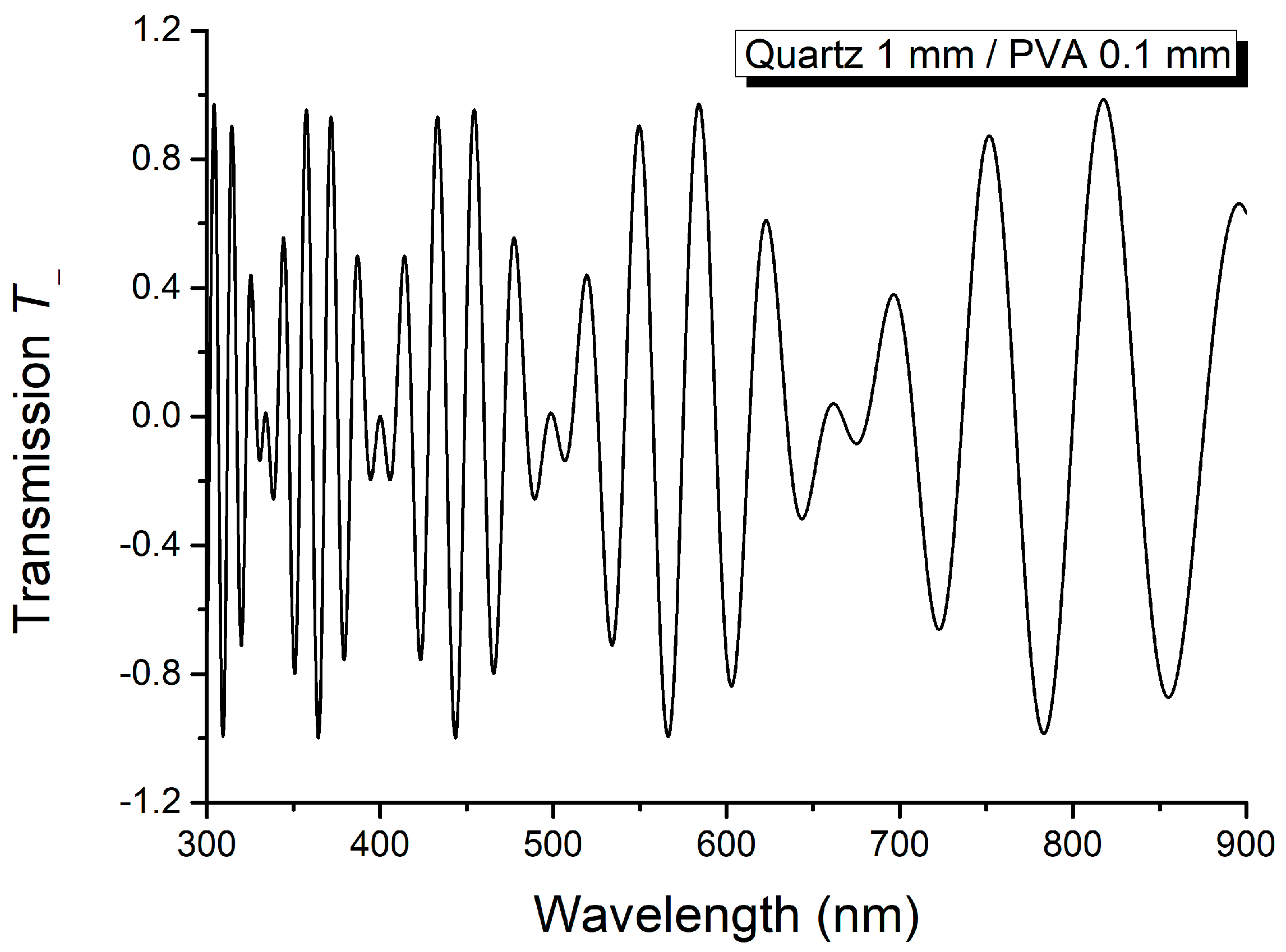
| 334.5; 400.0 | 0.0204275 | |
| 400.0; 497.3 | 0.0204440 | |
| 497.3; 657.3 | 0.0204297 | |
| Minima of channeled spectrum | ||
| 328.6; 391.6 | 0.0204254 | |
| 408.8; 511.0 | 0.0204400 | |
| 511.0; 682.3 | 0.0203445 | |
| Wavelength (nm) | Δn2 | Theoretical Relations |
|---|---|---|
| Maxima of channeled spectrum | ||
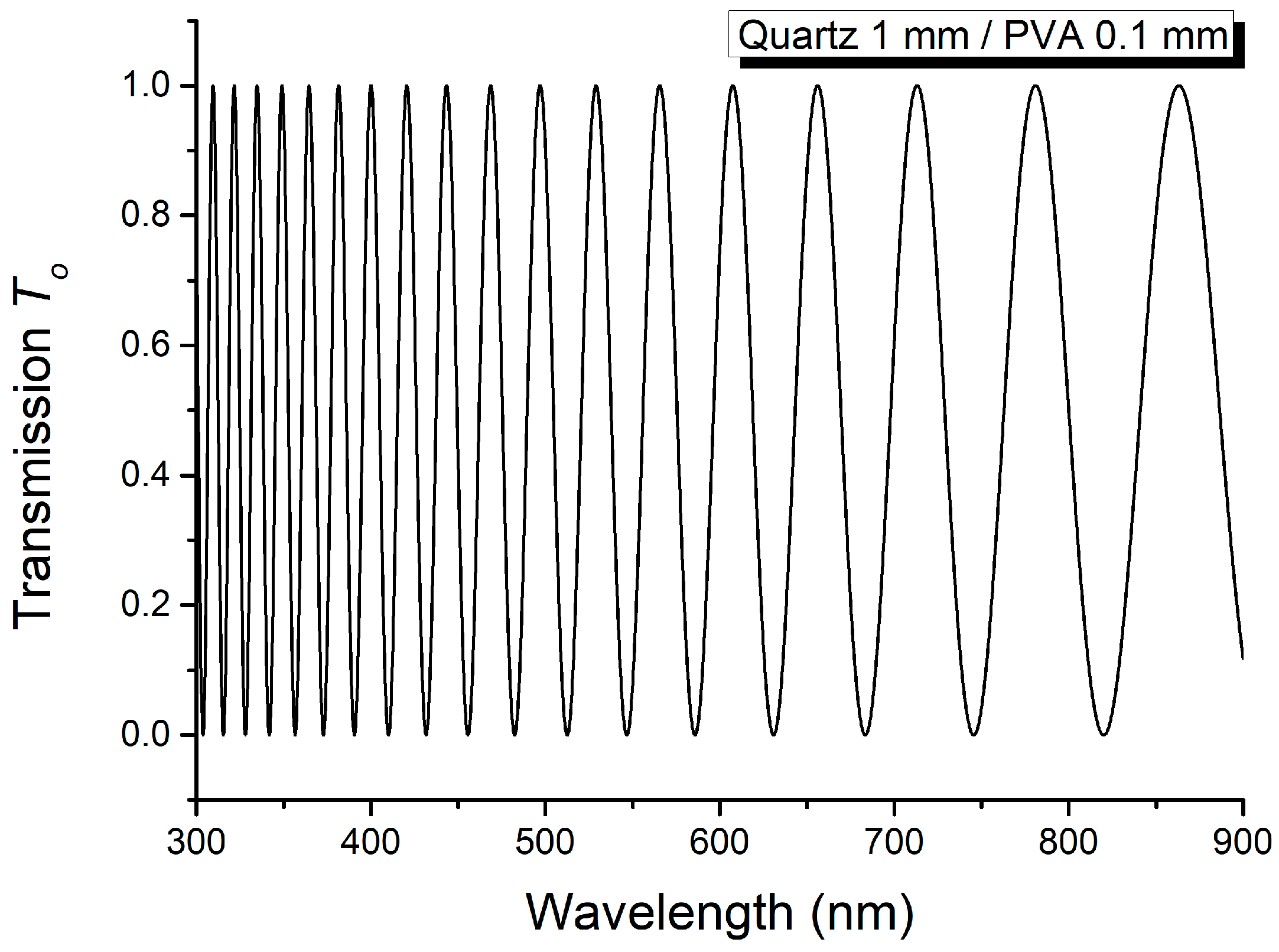
| 304.2; 357.2 | 0.0204362 | |
| 454.2; 584.0 | 0.0204355 | |
| 584.0; 817.6 | 0.0204338 | |
| Minima of channeled spectrum | ||
| 309.2; 364.4 | 0.0204376 | |
| 364.4; 443.4 | 0.0204526 | |
| 443.4; 566.2 | 0.0204440 | |
| 566.2; 793.2 | 0.0197968 | |
| Wavelength (nm) | Δn2 | Theoretical Relations |
|---|---|---|
| Maxima of channeled spectrum | ||
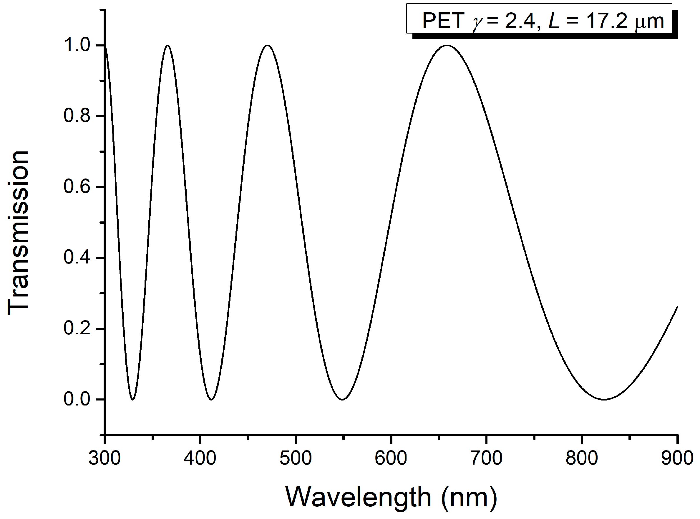
| 367.9; 409.0 | 0.2131284 | |
| 557.3; 657.2 | 0.2131755 | |
| 657.2; 800.7 | 0.2139944 | |
| Minima of channeled spectrum | ||
| 301.6; 328.6 | 0.2134060 | |
| 471.7; 541.4 | 0.2130212 | |
| 680.9; 835.9 | 0.2134900 | |
| Wavelength (nm) | Δn2 | Theoretical Relations |
|---|---|---|
| Maxima of channeled spectrum | ||
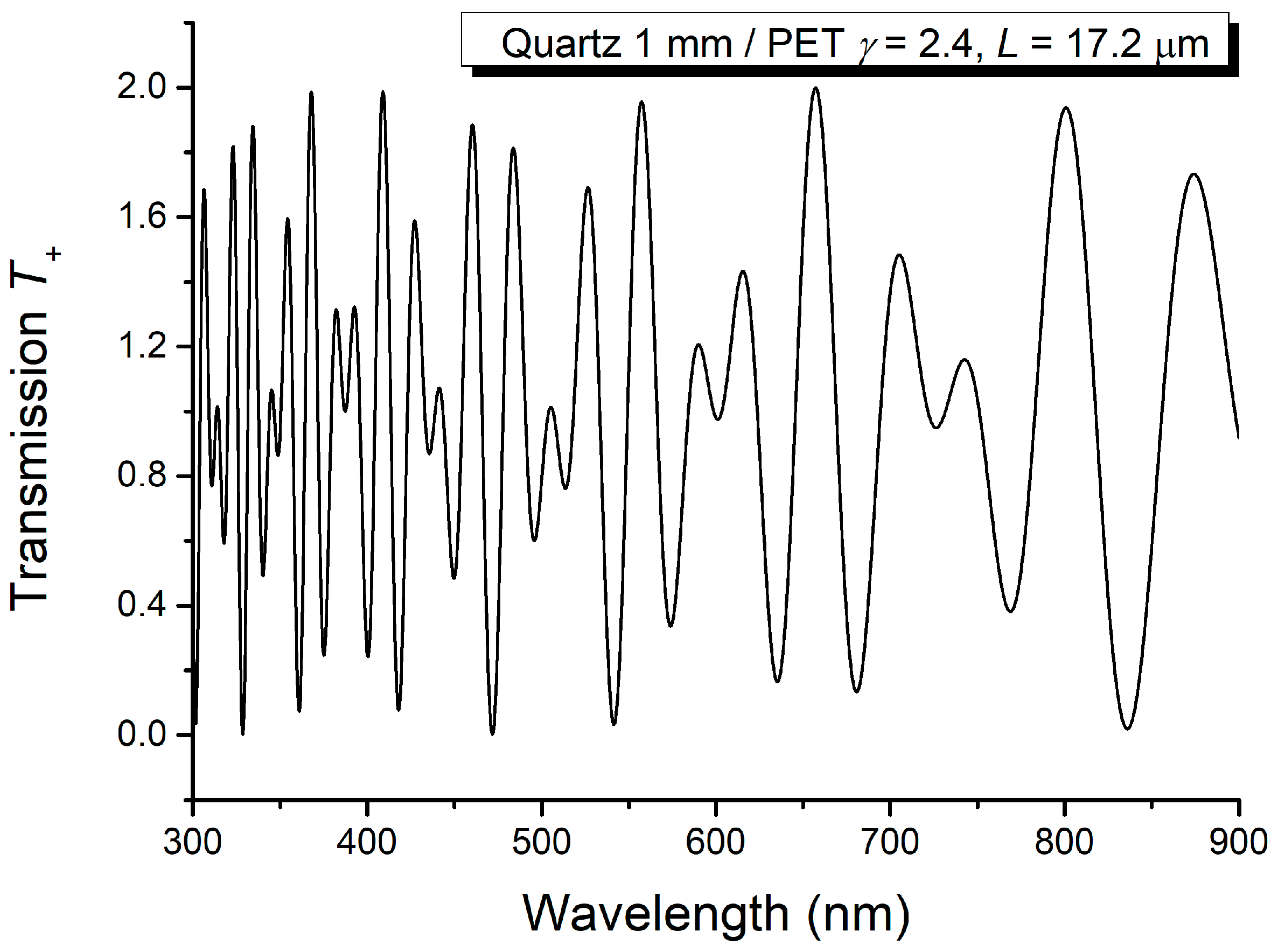
| 314.5; 344.5 | 0.2131525 | |
| 443.2; 504.2 | 0.2139827 | |
| 623.9; 750.4 | 0.2130108 | |
| Minima of channeled spectrum | ||
| 350.2; 387.4 | 0.2135917 | |
| 603.1; 721.9 | 0.2130696 | |
Disclaimer/Publisher’s Note: The statements, opinions and data contained in all publications are solely those of the individual author(s) and contributor(s) and not of MDPI and/or the editor(s). MDPI and/or the editor(s) disclaim responsibility for any injury to people or property resulting from any ideas, methods, instructions or products referred to in the content. |
© 2024 by the authors. Licensee MDPI, Basel, Switzerland. This article is an open access article distributed under the terms and conditions of the Creative Commons Attribution (CC BY) license (https://creativecommons.org/licenses/by/4.0/).
Share and Cite
Dorohoi, D.O.; Dimitriu, D.G. A Spectral Method for Rapidly Determining the Linear Birefringence of Thin Polymer Films. Molecules 2024, 29, 6007. https://doi.org/10.3390/molecules29246007
Dorohoi DO, Dimitriu DG. A Spectral Method for Rapidly Determining the Linear Birefringence of Thin Polymer Films. Molecules. 2024; 29(24):6007. https://doi.org/10.3390/molecules29246007
Chicago/Turabian StyleDorohoi, Dana Ortansa, and Dan Gheorghe Dimitriu. 2024. "A Spectral Method for Rapidly Determining the Linear Birefringence of Thin Polymer Films" Molecules 29, no. 24: 6007. https://doi.org/10.3390/molecules29246007
APA StyleDorohoi, D. O., & Dimitriu, D. G. (2024). A Spectral Method for Rapidly Determining the Linear Birefringence of Thin Polymer Films. Molecules, 29(24), 6007. https://doi.org/10.3390/molecules29246007