Abstract
Activated carbons were prepared from kenaf (Hibiscus cannabinus L.). Carbonization was carried out at 600 °C for 2 h, and activation was performed using air at 600 °C and using CO2 at 750 °C. The activated carbons obtained were treated with HNO3 and H2SO4. The samples were characterized by their chemical and physical structure. The activated carbons obtained were mainly macroporous, and their structure underwent major changes with the activation method and acid treatment. Activated carbons were alkaline and acid-treated carbons were neutral. They were used for phenol adsorption and a kinetic and mechanistic study of adsorption was carried out. The fit to the pseudo-second order and Elovich models was predominant. The rate-limiting step of the process was determined to be diffusion within the pores, as the experimental data fit the Bangham model. DFT simulation showed that the preferred adsorption position involves π-π stacking and that oxidation enhances this interaction. Furthermore, the simulation showed that the interaction of phenol with oxygenated functional groups depends on the type of functional group.
1. Introduction
Many biomass types may be used as raw materials to produce activated carbons. Numerous recent reviews on this topic provide lists of biomass materials used for this purpose. Some of these reviews are specific to a particular material type, raw material, preparation method or application, i.e., the preparation of activated carbon spheres [1] or composites [2], the use of biowastes [3,4], food waste [5] or spent tires [6], pyrolytic [7] or hydrothermal carbonization [8,9], application to carbon electrodes [10], adsorption of formaldehyde [11], dyes [12], or perfluorinated compounds [13].
Biomass is a renewable resource, accessible in many parts of the world and of varied origins. To obtain activated carbon, it is essential to select both the precursor and the carbonization and activation methods [7]. It should be considered that both textural properties and surface chemistry can influence the activity of these materials [14], so their study remains a topic of great interest.
The kenaf plant (Hibiscus cannabinus L.) has attracted attention as a source of natural fiber, with both ecological and economic advantages, because it grows rapidly [15,16]. It is a plant native to Africa that grows in high densities and can be adapted to other parts of the world. Under good conditions, kenaf grows up to a height of nearly 4 m in 5–6 months [17].
The outer stem bark contains soft and long fibers (bast), and the center of the stem is formed by short fibers (core). Although both contain fibers, it has been shown that the inside of kenaf has different properties for the outer skin.
The traditional use of kenaf is focused on the production of its outer fiber, e.g., for making ropes, sacs, canvases, and carpets [18]. However, new applications of kenaf have recently been developed, such as adsorbent material for oils and liquids [16], thermal and acoustic insulation in composite boards [15,19], automotive components [20], cementitious material components [21], and even as a source of natural chemicals [16,22]. These uses of external fiber result in a considerable amount of internal fiber with no obvious destination.
Although kenaf core fiber has some applications as animal bedding [16], it makes up most of the stem. Most of the production is discarded and may be considered as waste [23]. Its transformation into a useful product such as activated carbon would avoid the problem of its disposal, in addition to being a zero-cost material. Since kenaf core fiber is characterized by relatively high lignin and low ashes content [17], it is a promising raw material for producing high-quality activated carbon commercially to derive better economic value.
In the present study, activated carbon was prepared from kenaf core fiber. The activation process was carried out in two different manners: one with air and one with CO2. Some authors have also prepared activated carbon from this material. It has been used as a gas [24,25], organic [26,27], or heavy metals [28,29] adsorbent.
In addition, carbon oxidation treatments using sulfuric acid and nitric acid were studied.
The activation processes and the oxidative treatments were evaluated by characterizing their physical and chemical structure.
The kinetics of phenol adsorption were studied using different concentrations of carbon applying different kinetic models. These experiments and theoretical studies using DFT methods have allowed us to study the mechanism of phenol adsorption. Phenol is the simplest molecule of the phenol family. It is a significant contributor to water pollution [30] and is produced in natural or human activities [31]. For this reason, it is frequently found in drinking water sources. Moreover, phenols are characterized by the fact that they are often recalcitrant compounds, difficult to oxidize by classical methods, and, in many cases, poorly biodegradable. This compound was selected because the simplicity of its structure with only one functional group allows a simplified study especially in terms of theoretical simulation.
Also, phenol is a representative organic molecule for many possible pollutants or chemicals of interest that present aromatic structures accompanied by some polar functional groups, such as dyes, drugs, etc. Although there are some precedents for phenol adsorption with kenaf-activated carbons, these have been prepared by mixing the two types of fiber and using other preparation conditions [32,33,34].
This research work investigates the use of a waste material (kenaf internal fiber) to prepare activated carbon as an adsorbent, which we are unaware of having been used individually before. The activated carbon has also been modified with mineral acids and the materials obtained have been extensively characterized. To this experimental work, we have added an extensive theoretical study on the adsorption mechanism by means of kinetic and DFT models that provide information on the energy of the adsorption process and the influence of oxygenated functional groups on phenol adsorption.
2. Results and Discussion
Table 1 shows an abstract of the adsorbents used and how they are prepared.

Table 1.
Used adsorbents.
2.1. Physical Structure
2.1.1. Surface Area and Pore Size Distribution
The N2 adsorption isotherms of the activated kenaf carbons are shown in Figure 1. As shown in isotherms, carbonized kenaf has a poorly developed porosity, whereas all the activated carbons show a greater porosity (except KA). Isotherms with higher capacity are of type I (KAN, KCS, and KCN), type II (KAS), or type I + II (KC) [35]. The KC isotherm has a “step” in the middle of the isotherm that can be a significant volume of pores with a narrow distribution. This is not observed in the KC acid-treated carbons (KCN and KCS). Treatment with mineral acids produced a different effect on the two activated carbons. While treatment with H2SO4 showed the best result produced on carbon activated with CO2 (KCS), treatment with HNO3 is best suited for the one activated with air (KAN).
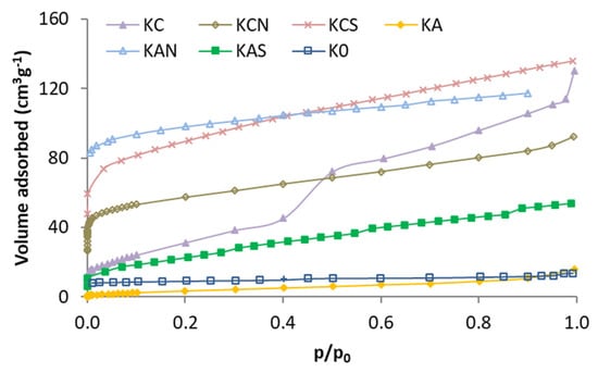
Figure 1.
Nitrogen adsorption isotherms of the kenaf carbons.
In Figure 2 and Figure 3, the pore size distribution is shown by applying the DFT model, and it can be observed that the effect of the treatments is different: the activation caused a loss of the narrow porosity, which was regained (at a different width) with acid oxidation treatments.
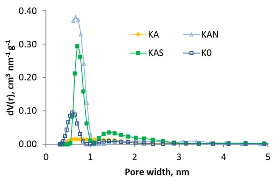
Figure 2.
Pore size distributions (based in DFT) of the samples activated with air and K0.
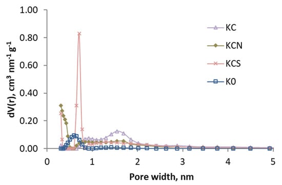
Figure 3.
Pore size distributions (based in DFT) of the samples activated with CO2 and K0.
By applying the BET, Dubinin–Radushkevich, and t-plot methods to the adsorption data, the values of the specific surface area (SBET), micropore volume (W0), adsorption energy (E0), and average half-pore width (L) were calculated. Such values are listed in Table 2.

Table 2.
Textural properties of the carbonized and activated samples.
In the kenaf carbons, the SBET and the micropore volume increased considerably with the activation and oxidation treatments, except in the KA sample. The SBET data, so low and similar to the initial data shown by the carbonized KA sample, may be due to a blockage of the porosity in the sample caused by: (i) products generated during the carbonization process and which have not been eliminated by activation with air; or (ii) by ash produced in the activation with air. Both can be eliminated in the acid treatment.
The activation treatment with CO2 (KC sample) had a limited effect on micropores: the volume increased nearly twice, but the adsorption energy (E0) and average diameter (L) were similar. However, it differed greatly with air activation (KA sample): micropores almost disappeared in KA, and the average diameter widened. This may be because the blocked pores are the narrowest, so the adsorption energy is lower as they do not have micropores, and the average width increases as the blocked pores cannot be measured.
The volume of meso- and macropores was determined by mercury porosimetry and is shown in Table 2. All kenaf samples showed a width distribution of porosity (except micropores in KA) and were essentially macroporous.
The mesopore volume was higher in the carbons of the KA series than in the KC series and was higher when sulfuric acid was used compared to nitric acid. The macropore volume, in contrast, was higher in the KC series than in the KA series and was also greater when sulfuric acid was used.
In the carbons from kenaf activated with air, the less developed wide porosity (meso and macropores) corresponds to activated carbon KAN, which was the furthest developed narrow porosity. In the activated carbons with CO2, the acid treatment decreased the macropore volume and increased the mesopore volume.
2.1.2. Scanning Electron Micrograph
Figure S1 shows SEM images of some samples. Despite undergoing the process of carbonization, activation, and oxidation, the carbons preserved the initial cellular structure corresponding to plant biochar.
2.2. Chemical Structure
2.2.1. Elemental Analysis
When the activation process occurs in kenaf biochar, a slight decrease in oxygen content can be observed since heat treatment eliminates thermally labile functional groups, such as some that contain oxygen. Although in the case of KA the activation is carried out with oxygen, the possible formation of oxygenated groups is less than the destruction of these groups by the effect of temperature.
On the contrary, the oxidation treatment produces an increased oxygen content in the samples, although the amount gained depends on the method and precursor used [36,37]. This effect is observed in the results shown in Table 3 where the oxidation treatments produced, in general, an increase in the oxygen content of the activated carbons, except for KCS. Besides increasing the oxygen content, this is greater when HNO3 is used than when H2SO4 is used, which has also been reported by other authors who compared HNO3 with other oxidizing agents [38,39]. The increased oxygen content can be attributed to the formation of functional groups with oxygen-carbon bonds, as well as to the formation of -NO2 groups, although it is difficult to assert that this would happen in all cases [39].

Table 3.
Elemental and proximate analysis.
HNO3 treatment also slightly increases nitrogen content, possibly due to remnants of the acid or any of its by-products or carbon nitration. Some authors [40,41] have attributed this observation to the formation of nitro and nitrate aromatic compounds.
Likewise, treatment with H2SO4 produces a slight increase in the sulfur content of the carbon samples treated, as seen in Table 3. This may be due to the same reasons as indicated for nitrogen, although a better explanation is the existence of sulfonic acid groups covalently bonded to carbon [42,43].
2.2.2. Proximate Analysis
According to the results shown in Table 3, a slight increase in the ash content with activation treatments was observed due to a loss of organic material in the process.
The oxidation treatment increases the volatile matter in all samples except KCS. This effect is more pronounced when nitric acid is used.
The increase in volatile matter can be attributed to the functional groups formed with the oxidation treatment. These functional groups are thermally labile and, therefore, constitute an important part of the volatile matter. This result is consistent with the variation in oxygen content. Concentrated acids may also degrade functional groups if they are not stable. This fact may explain the decrease in volatile matter in the KCS sample because the less oxidizing, more strongly acidic, and higher concentration compound is used. The degradation effect is, in this case, greater than the oxidation effect. Since this is not the case for KAS, it must be assumed that functional groups of different types must be formed during activation.
Another effect that is usually noticed is that the acid treatment leaches the mineral matter from the activated carbons.
2.2.3. X-Ray Photoelectron Spectroscopy
Table 4 shows the results of the elemental analysis determined by XPS analysis.

Table 4.
Elemental analysis (XPS) composition.
Acid treatments only increase oxygen content in those treated with nitric acid.
Furthermore, the nitrogen content increased in the samples treated with nitric acid (KAN and KCN) and the sulfur content increased in the samples treated with sulfuric acid (KAS and KCS).
In general, both types of elemental analysis are consistent in their results, indicating that the effect produced by different processes on the material’s surface (Table 4) was similar to the effect produced in the entire material as a bulk (Table 3).
The components of these spectra are assigned based on databases [44,45,46] and literature references [47].
As shown in Table 5, the activation process in carbons induced a slight increase in oxidized forms. The acid treatment produces a significant increase at the peak near 290 eV and a smaller decrease at the peak near 286 eV. No significant component has been detected at medium values of B.E. This can be explained by the fact that carbonyl groups (the main functional group of this component) are usually labile and must be lost in the carbonization step. Subsequent oxidation, when carried out in acid or aqueous acidic media, may form hydrogen-containing oxygenated groups [36] but is not likely to create new carbonyl groups, which are also alkaline and could react with acids.

Table 5.
The content of surface groups of carbons determined by the XPS method.
Two zones can be differentiated in the XPS spectrum of N 1s (Table 6). The first zone is around 398–401 eV and can be regarded as characteristic of pyrrolic nitrogen, pyridones, quaternary nitrogen, and other reduced forms of nitrogen. The second zone usually appears around 405 eV and is characteristic of oxidized nitrogen functionalities.

Table 6.
The content of surface groups of nitrogen and sulfur determined by the XPS method.
There are also two different zones in the case of sulfur (Table 6). One appears around 163–165 eV and is usually attributed to SH groups attached to the phenol ring and sulfur bonded to the carbon in the structures C-S-C and R-S-S-OR. The other zone ranges from 168 to 169 eV and is attributed to forms of sulfur in a high oxidation state, such as sulfates, sulfites, and sulfonic acids.
In surface nitrogen and sulfur groups, the most significant differences were observed when oxidation treatment was given to the samples. In the case of nitrogen, all samples show the reduced form of nitrogen, whereas in the case of modification with nitric acid carbons, a second characteristic peak group from oxidized nitrogen or -NO2 groups is also shown in Figure 4. In the case of sulfur (Figure 5), there is initially a high amount of sulfur in a high oxidation state. This is reduced in the activation treatment, but treatment with sulfuric acid increases the proportion of oxidized sulfur again. This has mainly been attributed [39,40,41,48,49] to the formation of sulphonic groups, although other sulfur functional groups may have formed.
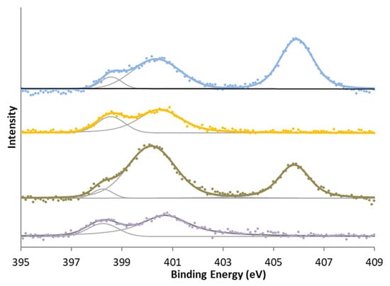
Figure 4.
N 1s XPS spectra for (bottom to top) KC, KCN, KA, and KAN.
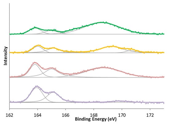
Figure 5.
S 2p XPS spectra for (bottom to top) KC, KCS, KA, and KAS.
2.2.4. Point of Zero Charge (PZC) and Total Surface Acidity and Basicity
Table 7 shows the PZC results of different samples and acid/basic groups determined by titration. Oxidized carbons have a lower PZC than other samples. In kenaf carbons, there are no differences according to the acid used, while in commercial activated carbons, there are significant differences between nitric and sulfuric acid [39].

Table 7.
PZC and total acidity and basicity of the samples.
The adsorbents whose PZC is basic have a higher contribution of basic groups on their surface, whereas those who have a PZC near neutral pH show a similar contribution of acidic and basic groups. In addition, the activation process significantly increased the number of alkaline groups on the carbon surface. The total acid-active sites on the surface increased with the oxidation treatment, whereas the total basic active sites decreased.
The most significant number of acid-active sites was obtained after treatment with nitric acid, as this fixed the largest amount of oxygen. Interestingly, the activated carbon treated with sulfuric acid was as acidic as the one treated with nitric acid but with less acidic functional groups. This can be explained by the formation of sulfonic acid groups, which are more acidic than carboxyl or phenol/hydroxyl groups.
2.3. Kinetic Experiments
2.3.1. Kinetic Models
The evaluation of phenol concentration was studied using different adsorbent ratios. As expected, the higher the amount of activated carbon used, the better the pollutant removal. More than 90% of the phenol is removed with all adsorbents except the less porous ones (KA and KAS) where 80% and 60% of the phenol is removed after 300 h. On the other hand, the KC and KCN carbons stand out, where equilibrium is achieved in about 100 h, and 94 and 98% of the phenol has been adsorbed. Figure 6 shows the results for KCN activated carbon. The plots of the other adsorbents are shown in Supplementary Materials (Figures S2–S6).
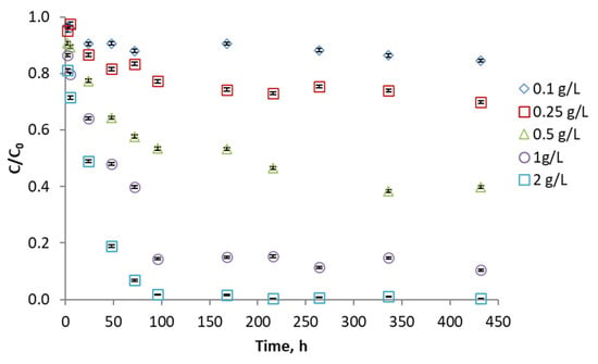
Figure 6.
Phenol adsorption kinetics with KCN activated carbon using different proportions of adsorbent.
Generally, kenaf carbons activated with CO2 have a greater phenol adsorption capacity, while air-activated kenaf carbons (KAN and KAS) present poor results.
Various kinetic models (pseudo-first and pseudo-second order, Elovich, Natarajan-Khalaf and Bhattacharya-Venkobachar) have been applied to the experimental data obtained. The validity of the fit to one or the other model was evaluated by calculating the error with the following formula:
where qt,calc is the adsorbed quantity calculated according to the model, qt,exp is the experimentally adsorbed quantity, and n is the number of data of the experiment. The results obtained are shown in Table 8.

Table 8.
Error values calculated from the application of the different models to kenaf carbons.
Given the calculated error of kinetic results obtained, all the carbons seem to fit better to the pseudo-second order or Elovich kinetic models, especially at higher carbon concentrations. Although the errors obtained when applying the Elovich model are small, a better linear fit is obtained with the pseudo-second order model (Table S1). The fact that the Elovich and PSO models give good fits is not surprising, as both can be considered very similar when the degree of surface coating is low [50]. It also implies that the adsorption process developed experimentally by us is far from reaching saturation since the Elovich model is valid far from chemical equilibrium and the PSO model is valid when the ratio of occupied sites to the amount of adsorbate is high (see more information in the Supplementary Materials).
The model with the worst fit to the experimental data is that of Natarajan y Khalaf. The adjustment is more accurate the higher the proportion of adsorbent used. A slightly different behavior is KCN, whose kinetics do not fit the Elovich model particularly well but does fit the PSO model. It should be remembered that this is the activated carbon with which the best results have been obtained.
Table 9 shows the calculated values (PSO model) of k2 and adsorption capacity qe for the 2 g L−1 test. For comparison, the experimental values of qe are also shown. These are similar to the calculated values, which demonstrates the good fit of the PSO model. The rate constants and adsorption capacity are lower for the air-activated adsorbents than for the CO2-activated ones. In KA and KAS, this can be explained by a lower pore development, as shown in the characterization discussion. KAN has a higher specific surface area, but for some reason, the adsorption is slower (Figure S3). This can be explained by the pore width distribution not being adequate. Thus, this adsorbent has the smallest volume of macropores of all activated carbons and also stands out for having hardly any wide micropores, between 1 and 2 nm (Figure 3), which may hinder the diffusion of phenol.

Table 9.
Pseudo-second order constant for the adsorption of phenol in activated carbons (rate: 2 g L−1).
It is more complex to explain why the two adsorbents with the largest BET surface area do not adsorb the most. One factor explaining this may be surface chemistry, which is more suitable for KCN than KCS (see the Section 2.4).
2.3.2. Mechanistic Models
The adsorption mechanism is presumed to involve three stages that can influence the speed of the process: mass transfer of the adsorbate molecules across the external boundary layer (film diffusion), intraparticle diffusion, and diffusion into pores. One last step (adsorption at a site on the surface) is considered a fast process if it is physisorption (see below for theoretical simulations) and does not affect the adsorption kinetics.
Thus, diffusional kinetic models have also been applied to the adsorption of phenol to understand better the importance of the different stages in the adsorption process. We have therefore applied three mechanistic models: (a) the liquid film diffusion or Boyd model to study whether the determining step in the process is the mass transfer from solution; (b) the intra-particle diffusion model or Weber and Morris model; and (c) the Bangham model, which determines whether the limiting step is diffusion in narrow pores. The errors calculated from applying these three models to the experimental data are shown in Table 10. Also, since in order to consider one of the stages as limiting the process, a linearity in its fit must be observed, the values of R2 have been calculated (Table S2).

Table 10.
Error values from the application of the different models to carbons.
If we consider the calculated errors (Table 10), the best fits are achieved for the Bangham model, implying that the process’s rate-controlling step is diffusion inside the pores [51]. However, if there are several successive stages in a process, it can be perceived that some of the previous stages influence the speed since, before reaching the diffusion inside the pores, the molecules must be transferred from the liquid to the activated carbon and then enter through the wider pores until they reach the narrower pores. Therefore, in some cases, low error values are observed in the liquid film diffusion (KAN and KAS) or intraparticle diffusion (KAN) stages. It should be remembered that KAN carbon shows a somewhat different behavior compared to CO2 activated carbon, which has a similar specific surface area. This may be because there are several slow stages rather than a single one, which explains its slower adsorption.
As in the kinetic models, better fits are obtained using larger amounts of adsorbent. The amount of activated carbon used does not generally influence the adsorption mechanism.
If the R2 values are used, the conclusions are the same. Again, the best fit is achieved with the Bangham model, and for the KAN adsorbent, high R2 values are obtained for all three models.
2.4. DFT Simulations
To study how a phenol molecule adsorbs on a graphene molecule, the M1 and M2 models were simulated separately (Figure 7) and then together (Figure 8).
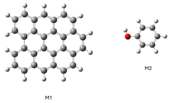
Figure 7.
Representation of the structure of models of graphene (M1) and phenol (M2) molecules.
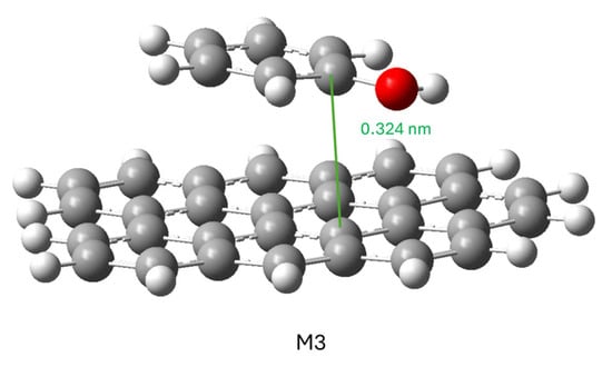
Figure 8.
Representation of structure with minimal potential energy.
To calculate the conjugate model, the phenol molecule was placed in various positions and orientations with respect to the graphene molecule: on the graphene molecule or to one side; with the hydroxyl group close to the graphene molecule, far away or in a neutral position; and with the phenol aromatic ring parallel or perpendicular to the plane of the graphene molecule. In all cases, the minimization of the ensemble’s energy led to the same result shown in Figure 8: the phenol molecule was positioned parallel to the graphene molecule, so this structure can be considered the most stable for this adsorption.
The interaction between the two gave a result of ΔG= −2.97 KJ mol−1. This differs from the situation in which both molecules are solvated in water, so the adsorption from the aqueous phase must be considered favorable.
The following calculated model was an attempt to study the energy of the phenol molecule’s approach to the graphene surface. The keyword scan was used to calculate the system’s energy as the two molecules gradually moved away from each other. Two close atoms, one from each molecule, were chosen and separated in 0.5 Å steps.
This simulation could not be completed because, after several steps, the calculation was aborted due to a problem related to the geometrical constraints imposed. However, in the few calculated steps, we could observe that the molecules did not separate from each other but that the phenol molecule slid over the surface of the graphene molecule to move the two atoms considered away from each other. This indicates that (a) the adsorption is stable; (b) the mobility of a phenol molecule on the surface of a carbonaceous material of this type is possible because no large variations in the energy of the system were observed; (c) the type of adsorption is physisorption.
To carry out this study, we changed the method and used an IRC (intrinsic reaction coordinate) calculation [52]. This was possible, and Figure 9 shows the relative energy with respect to the reaction coordinate and the distance (0 equals the minimum energy distance) between the two reference atoms.
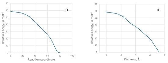
Figure 9.
Representation of relative energy with respect to the reaction coordinate (a) and with respect to the distance between the two atoms (b). Model M3.
It can be seen that the energy decreases continuously as the two molecules approach each other, which corresponds to a typical physisorption process, and there is no activation energy in the adsorption. We have also provided a video (IRC-G.mp4) of the process from two perspectives.
The following simulation was used to study the effect of oxygenated functional groups on adsorption. For this purpose, the M1 model was modified by adding a carboxyl, a carbonyl, and a hydroxyl group. The model phenol molecule was placed in such a way that it interacted with the graphene plane (π-π stacking) and each functional group. The result of the energy optimization is the four models (M4 to M7) shown in Figure 10. We have also provided an IRC video of the M4 model (IRC-GO.mp4).
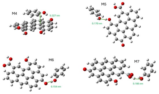
Figure 10.
Stable structures of the interaction of phenol molecules with oxidized graphene. M4, π-π stacking; M5, interaction with hydroxyl; M6, interaction with carbonyl; and M7, interaction with carboxyl.
The calculated ΔG, ΔH, and ΔS values are shown in Table 11.

Table 11.
Calculated ΔG values for the different simulations.
These results show that binding by π-π stacking is more favorable if oxygenated groups are present (M4) than if they are absent (M3) for phenol adsorption. This result, which has traditionally been discussed in the literature, can be explained in this case for several reasons. One is that the oxidized graphene model has a high amount of oxygen (16.5 wt.%), implying a high degree of polarity. The second reason is that phenol has a polar functional group (-OH) and an apolar functional group (aromatic ring). Being a moderately polar substance, oxidized graphene can compete with the water solvation of phenol, increasing its adsorption capacity. In our case (Table 9), it can be observed that in the KA series the adsorption capacity decreases upon CA oxidation while in the KC series the opposite happens. It is a subject, therefore, where it is difficult to reach simple conclusions.
The adsorption enthalpy values are decisive since the best-performing models (M3, M4, and M6) clearly show more negative values than the other models. The presence of oxygenated groups represents a slight variation (−0.81 kJ mol−1) compared to their absence. The entropy variation presents two different behaviors. When phenol is directly bound to oxygenated groups (M5, M6, and M7), the entropy decreases less than in the other two models, so this thermodynamic factor is favored in these cases. At equal phenol adsorption position, the presence of oxygenated groups (M4) is slightly more favorable than their absence (M3).
It is also shown that the interaction of phenol with the different functional groups does not give the same results. While the interaction with a carbonyl group (M6) is even more favorable than π-π stacking, the interaction with hydroxyl or carboxyl is unfavorable. It should not be forgotten that this comparison is with respect to both model molecules being dissolved in water. Even a favorable interaction in absolute terms can give a negative result if the solvation of oxidized graphene and phenol separately is more stable. In this case, it is possible that the hydrogen-bridging bonds that can form between the hydroxyl and carboxyl groups with water explain this result. It is more difficult in carbonyl because it does not have hydrogen atoms bonded to electronegative atoms, so the loss of solvation with water is not so significant.
The IRC energy data for the formation of the M4 model are shown in Figure 11. We have also provided a video of the M4 model’s IRC.
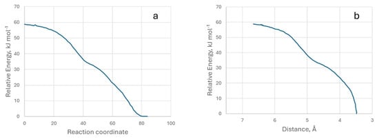
Figure 11.
Representation of relative energy with respect to the reaction coordinate (a) and the distance between the two atoms (b). Model M4.
Table 12 shows the calculated values for the HOMO and LUMO orbitals of the different systems, as well as the gap between them.

Table 12.
Calculated energy values (in eV) for HOMO and LUMO orbitals.
The HOMO energy values are similar to each other except for phenol. In the case of LUMO, the presence of oxygen atoms on graphene results in lower (more negative) energy values. The consequence of this fact is that the gap is smaller when the graphene is oxidized.
Using the NBO Analysis and the second-order perturbation theory, it is possible to calculate the donor–acceptor interactions between both molecules (phenol and oxidized graphene/graphene) and estimate the energetic importance of each interaction. Table 13 shows the main interactions for each calculated model. To help understanding, images of these models with the numbering of each atom are shown in Supplementary Materials (Figures S9–S13).

Table 13.
Main donor–acceptor interactions in M3, M4, M5, M6, and M7 models.
In the M3 model, an electron donation from the hydroxyl (O56 and H57) to an anti-bonding orbital of the C10 of graphene is observed. However, there is also a donation from the C9–C10 bond of graphene to the 1 s anti-bonding orbital of the H of hydroxyl.
In the M4 model the behavior is different: there are only donors on the oxidized graphene and acceptors on the phenol molecule. In all cases except the last one, they are π-π transfers and in the last one the acceptor is the H55 of the phenol hydroxyl group.
In the following models, the donor–acceptor interactions have a higher energetic value. This is due to the approaching polar functional groups that will give rise to dipoles and with them stronger van der Waals forces and even hydrogen bridge bonding. Thus, in the M5 model, the H37 of the hydroxyl of the oxidized graphene yields electrons to the C45–O54 bond of the phenol and to the H55 of the hydroxyl of the phenol, this being the most important donor–acceptor interaction. On the other hand, O54 of the phenol hydroxyl donates electrons to the H37 mentioned above.
In the M6 model, there is donation and acceptance in both directions, but the most important is from O35 carbonyl to H55 phenol hydroxyl. In this case, it can be stated that there is an evident hydrogen bridge bond. In the M7 model, donation acceptance is present in both directions as well. The most important is from H34 of carboxyl to H55 of phenol hydroxyl. The other two interactions can be considered a hydrogen bridge bond.
3. Materials and Methods
3.1. Preparation of the Samples
Activated carbons were prepared from kenaf using the inside of the stem. A vertical tubular furnace was used to produce biochar and activated carbons. The carbonization of the samples was carried out at 600 °C. The heating rate was 10 °C min−1 under a constant N2 flow of 200 mL min−1. The isothermal carbonization time was 2 h. The carbonized sample kenaf was named K0. The yield was 29.2%.
The activation temperatures were 750 °C when the activating agent was CO2 and 600 °C when the activating agent was air. In both cases, an activating agent flow equal to 200 mL min−1 was used, with a heating rate of 10 °C min−1. The isothermal activation time at maximum temperature was 2 h. The activated carbons were called KC and KA when the activating agents were CO2 and air, respectively. The yields were 56.1% (KA) and 78.4% (KC).
The acidic activated carbons were prepared by treating the activated carbons of kenaf with sulfuric (commercial 98%) or nitric acid (5 M) at a proportion of 0.05 g of carbon per milliliter of the acid used. The mixture was stirred for 90 min at ambient temperature. Later, the acidic carbons were filtered and washed with water in Soxhlet until a constant pH was reached, and then they were dried for 24 h at 110 °C.
3.2. Materials Characterization
Nitrogen adsorption isotherms at 77 K were determined using an Autosorb of Quantachrome (Anton Paar Spain S.L.U., Madrid, Spain) after outgassing the samples for 24 h at 140 °C to a residual vacuum. A Quantachrome porosimeter, Poremaster-60 (Anton Paar Spain S.L.U., Madrid, Spain), was used to obtain the mercury intrusion curves with sensitivity from 950 nm to 3.6 nm. The sample morphology was observed using a scanning electron microscope Hitachi S-4800 II (Hitachi Europe Ltd., Slough, UK); the imaging was performed in the high vacuum mode at an accelerating voltage of 10 kV, using secondary electrons.
The proximate analysis (moisture, fixed carbon, volatile matter, ash) was determined by a thermo-gravimetric method using a Mettler model TGA/SDTA 851e (Mettler Toledo, Cornellá del Llobregat, Spain). Moisture was measured by heating from 45 to 105 °C in an N2 atmosphere (30 mL min−1) at a heating rate of 10 °C min−1, with an isothermal time of 7 min at 105 °C. To determine the volatile matter content, the sample was heated to 600 °C at a heating rate of 25 °C min−1 and to 900 °C at a heating rate of 35 °C min−1, and this temperature was maintained for 7 min. Finally, at 900 °C, the N2 atmosphere was changed to air, and the sample was kept burning for 27 min. The weight lost was the fixed carbon content of the sample; the residual remaining mass was the ash content.
The elemental analysis (C, H, N, S, O) was carried out using a LECO CHNS-932 elemental analyzer (LECO Corporation, St. Joseph, MI, USA). C, H, N, and S were analyzed, and the difference was assigned to ash (proximate analysis) and oxygen content. Moisture determined by thermogravimetry was deduced.
X-ray photoelectronic spectra were obtained with a K-Alpha de Thermo Scientific (Thermo Fisher Scientific, Waltham, MA, USA) photoelectron spectrometer using monochromatic Al-Kα radiation. The source operated at 12 kV, 6 mA. The measurements were performed under a vacuum of 2.2 × 10⁻⁵ Pa.
The points of zero charge (PZC) values were determined using the method proposed by Valente Nabais and Carrott modified [53]. The samples were placed in contact with a NaNO3 0.1 M solution and stirred for 48 h at 25 °C. After this time, the sample was filtered, the pH of the solution was measured, and a PZC value was assigned to it.
Finally, the number of acidic and basic groups was evaluated by acid-base titration. To determine the acid groups, 0.15 g samples were suspended and stirred in a 30 mL solution of 0.01 M NaOH for 24 h at 25 °C, and the resulting solution was titrated with a 0.01 M HNO3 solution. Then, to determine alkaline groups, the activated carbons (0.15 g) were suspended in a 0.01 M HNO3 solution under the same conditions and titrated with a 0.01 M NaOH solution.
3.3. Adsorption
To study the adsorption kinetics of both adsorbates, a solution of 100 mg L−1 of phenol was used at pH = 7 and keeping the ionic strength constant at 0.01 M.
The kinetic study was carried out in glass tubes in which 25 mL of the starting solution and the corresponding amount of adsorbent were added in each case. The experiments were carried out at 25 °C in a thermostatic platform bath with a stirring of 45 min−1. The pH was achieved by adding phosphate salts (Na2HPO4/NaH2PO4).
The adsorbate concentration was determined after filtering the sample with a 0.45 µm filter using a Varian Cary 50 Probe UV-Visible spectrophotometer (Agilent, Santa Clara, CA, USA) at a wavelength of 269 nm (the wavelength of maximum phenol absorption). The tests were repeated at least twice. The phenol UV-Vis spectrum and calibration curve are shown in Figures S7 and S8.
3.4. Theoretical Model Fits
Further information on the kinetic and mechanistic models used in this research can be found in the Supplementary Materials.
No lineal correlation was used to evaluate the model’s goodness of fitting and suitability. The R2 values of the linear fit (Tables S1 and S2) have been included in the Supplementary Materials for comparison purposes.
Although the linear regression method is the most widely used due to its simplicity, it is known [54] that the linearization process changes the independent/dependent variables. Also, this process could introduce propagate errors to the independent/dependent variables, which could cause inaccurate estimations of the parameters. Models with more than two variables, such as Elovich’s, must assume certain approximations. The nonlinear method can provide consistent and accurate estimations for model parameters [55].
3.5. DFT Calculations
The computational study was performed using the Gaussian16 (Revision A.03) package [56] with the PW6B95D3/Def2SVP level of theory. The calculations were carried out in water (SMD model) [57]. Given the difficulty of calculating unbound systems and the fact that we initially observed that the changes in the system’s potential energy were very small and made it difficult to reach a minimum, we selected the option opt = tight for the optimization. A consequence of this decision is that more steps are needed to obtain the minimum energy. For the same reason, we use the option scf = (xqc,verytight).
The thermodynamic parameters for the two-molecule models were calculated by subtracting the calculated data of the individual molecules from the joint model result.
To study which are the most important interactions between phenol and graphene we have used NBO Analysis. This method transforms the wave functions used in the DFT calculation into localized forms (bonds and orbitals). It is often used to determine the Lewis structure of a compound but, in our case, we have used the second order perturbation theory to calculate the donor–acceptor interactions and estimate the energetic importance of each one.
4. Conclusions
Kenaf core is a material suitable for manufacturing activated carbons for use in the adsorption of phenolic compounds. The activation method and the subsequent modification of the chemical surface with mineral acids strongly influence the adsorption capacity. Very different products can be obtained from the same biochar, so knowing the preparation methods and their consequences is essential. The use of mineral acids increases the specific surface area, oxidizes the surface of the activated carbon depending on the acid used, and increases the adsorption capacity.
The kinetic studies carried out preferably follow the PSO and Elovich models. The determining step in the adsorption kinetics is the diffusion of phenol into the pores, although all steps seem to influence the process for an adsorbent.
Simulations of adsorption by the DFT method show that the presence of oxygenated groups in the adsorbent improves the adsorption capacity by π-π stacking. However, oxygenated functional groups can favor or disfavor the binding of phenol to them depending on the type of functional group.
The DFT method has been shown to be an important tool for understanding adsorption phenomena, so its use should be expanded in future studies. In addition to the results shown here, other factors that influence the adsorption process, such as pH, temperature, or adsorbate concentration, should be studied. The adsorbents used are likely to be used to remove other contaminants.
Supplementary Materials
The following supporting information can be downloaded at: https://www.mdpi.com/article/10.3390/molecules29204941/s1, Figure S1. SEM images of samples (a) KAN; (b) KAS; (c) KCN; and (d) KCS; Figure S2. Phenol adsorption kinetics with KA activated carbon using different proportions of adsorbent; Figure S3. Phenol adsorption kinetics with KAN activated carbon using different proportions of adsorbent; Figure S4. Phenol adsorption kinetics with KAS activated carbon using different proportions of adsorbent; Figure S5. Phenol adsorption kinetics with KC activated carbon using different proportions of adsorbent; Figure S6. Phenol adsorption kinetics with KCS activated carbon using different proportions of adsorbent; Figure S7. UV spectrum of phenol; Figure S8. Calibration curve of phenol solution; Figure S9. Numbering of atoms in the M3 model; Figure S10. Numbering of atoms in the M4 model; Figure S11. Numbering of atoms in the M5 model; Figure S12. Numbering of atoms in the M6 model; Figure S13. Numbering of atoms in the M7 model. Table S1. R2 values of the application of the pseudo-second order and Elovich kinetic models to the experimental data; Table S2. R2 values of the application of Bangham, intraparticle diffusion and film diffusion models to the experimental data; information about theoretical kinetic models used in this research with references. References [58,59,60,61,62,63,64,65,66] are cited in the Supplementary Materials.
Author Contributions
Conceptualization, C.J.D.-V.; validation, D.O.-M.; investigation, D.O.-M. and M.A.M.-C.; resources, M.A.M.-C.; data curation, D.O.-M. and C.J.D.-V.; writing—original draft, D.O.-M.; writing—review and editing, C.J.D.-V. and M.A.M.-C.; visualization, D.O.-M. and C.J.D.-V.; supervision, C.J.D.-V. and M.A.M.-C.; project administration, M.A.M.-C.; funding acquisition, C.J.D.-V. All authors have read and agreed to the published version of the manuscript.
Funding
This research has been funded by Junta de Extremadura (Technologists Training Grant TEC07014, awarded to D. Omenat-Morán) and the Ministerio de Ciencia e Innovación of Spain, grant n° PID2021-124021OB-I00.
Institutional Review Board Statement
Not applicable.
Informed Consent Statement
Not applicable.
Data Availability Statement
Dataset available on request from the authors.
Conflicts of Interest
The authors declare no conflict of interest.
References
- Lan, J.; Wang, B.; Bo, C.; Gong, B.; Ou, J. Progress on Fabrication and Application of Activated Carbon Sphere in Recent Decade. J. Ind. Eng. Chem. 2023, 120, 47–72. [Google Scholar] [CrossRef]
- Ullah, S.; Rehman, A.U.; Najam, T.; Hossain, I.; Anjum, S.; Ali, R.; Shahid, M.U.; Shah, S.S.A.; Nazir, M.A. Advances in Metal-Organic Framework@activated Carbon (MOF@AC) Composite Materials: Synthesis, Characteristics and Applications. J. Ind. Eng. Chem. 2024, 137, 87–105. [Google Scholar] [CrossRef]
- Wong, S.; Ngadi, N.; Inuwa, I.M.; Hassan, O. Recent Advances in Applications of Activated Carbon from Biowaste for Wastewater Treatment: A Short Review. J. Clean. Prod. 2018, 175, 361–375. [Google Scholar] [CrossRef]
- De Gisi, S.; Lofrano, G.; Grassi, M.; Notarnicola, M. Characteristics and Adsorption Capacities of Low-Cost Sorbents for Wastewater Treatment: A Review. Sustain. Mater. Technol. 2016, 9, 10–40. [Google Scholar] [CrossRef]
- Kosheleva, R.I.; Mitropoulos, A.C.; Kyzas, G.Z. Synthesis of Activated Carbon from Food Waste. Environ. Chem. Lett. 2019, 17, 429–438. [Google Scholar] [CrossRef]
- Jones, I.; Zhu, M.; Zhang, J.; Zhang, Z.; Preciado-Hernandez, J.; Gao, J.; Zhang, D. The Application of Spent Tyre Activated Carbons as Low-Cost Environmental Pollution Adsorbents: A Technical Review. J. Clean. Prod. 2021, 312, 127566. [Google Scholar] [CrossRef]
- Kumar Mishra, R.; Singh, B.; Acharya, B. A Comprehensive Review on Activated Carbon from Pyrolysis of Lignocellulosic Biomass: An Application for Energy and the Environment. Carbon Resour. Convers. 2024, 7, 100228. [Google Scholar] [CrossRef]
- MacDermid-Watts, K.; Pradhan, R.; Dutta, A. Catalytic Hydrothermal Carbonization Treatment of Biomass for Enhanced Activated Carbon: A Review. Waste Biomass Valoriz. 2020, 12, 2171–2186. [Google Scholar] [CrossRef]
- Jain, A.; Balasubramanian, R.; Srinivasan, M.P. Hydrothermal Conversion of Biomass Waste to Activated Carbon with High Porosity: A Review. Chem. Eng. J. 2016, 283, 789–805. [Google Scholar] [CrossRef]
- Abioye, A.M.; Ani, F.N. Recent Development in the Production of Activated Carbon Electrodes from Agricultural Waste Biomass for Supercapacitors: A Review. Renew. Sustain. Energy Rev. 2015, 52, 1282–1293. [Google Scholar] [CrossRef]
- Rengga, W.D.P.; Sudibandriyo, M.; Nasikin, M. Development of Formaldehyde Adsorption Using Modified Activated Carbon—A Review. Int. J. Renew. Energy Dev. 2012, 1, 75–80. [Google Scholar] [CrossRef]
- Katheresan, V.; Kansedo, J.; Lau, S.Y. Efficiency of Various Recent Wastewater Dye Removal Methods: A Review. J. Environ. Chem. Eng. 2018, 6, 4676–4697. [Google Scholar] [CrossRef]
- Mc Namara, J.D.; Franco, R.; Mimna, R.; Zappa, L. Comparison of Activated Carbons for Removal of Perfluorinated Compounds from Drinking Water. J. Am. Water Work. Assoc. 2018, 110, E2–E14. [Google Scholar] [CrossRef]
- Mahene, W.L.; Kivevele, T.; Machunda, R. The Role of Textural Properties and Surface Chemistry of Activated Carbon Support in Catalytic Deoxygenation of Triglycerides into Renewable Diesel. Catal. Commun. 2023, 181, 106737. [Google Scholar] [CrossRef]
- Halip, J.A.; Tahir, P.M.; Cheng, A.; Choo, A.C.Y.; Ashaari, Z. Effect of Kenaf Parts. Bioresources 2014, 9, 1401–1416. [Google Scholar]
- Hong Ng, S.; Md Tahir, P.; Mohamad, R.; Abdullah, L.C.; Choo, A.C.Y.; Yee Liong, Y. Effect of Pretreatment Process on Bioconversion of Kenaf (Hibiscus cannabinus L.) Core to Glucose. Bioresources 2013, 8, 2010–2017. [Google Scholar]
- Hamidon, M.H.; Sultan, M.T.H.; Ariffin, A.H.; Shah, A.U.M. Effects of Fibre Treatment on Mechanical Properties of Kenaf Fibre Reinforced Composites: A Review. J. Mater. Res. Technol. 2019, 8, 3327–3337. [Google Scholar] [CrossRef]
- Umair, M.; Azis, N.; Halis, R.; Jasni, J. Investigation of Kenaf Paper in the Presence of PVA for Transformers Application. Materials 2020, 13, 5002. [Google Scholar] [CrossRef]
- Sreenivasan, S.; Sulaiman, S.; Baharudin, B.T.H.T.; Ariffin, M.K.A.; Abdan, K. Recent Developments of Kenaf Fibre Reinforced Thermoset Composites: Review. Mater. Res. Innov. 2013, 17, s2–s11. [Google Scholar] [CrossRef]
- Zhu, S.; Xie, J.; Sun, Q.; Zhang, Z.; Wan, J.; Zhou, Z.; Lu, J.; Chen, J.; Xu, J.; Chen, K.; et al. Recent Advances on Bast Fibre Composites: Engineering Innovations, Applications and Perspectives. Compos. B Eng. 2024, 284, 111738. [Google Scholar] [CrossRef]
- Guo, A.; Sun, Z.; Satyavolu, J. Impact of Modified Kenaf Fibres on Shrinkage and Cracking of Cement Pastes. Constr. Build. Mater. 2020, 264, 120230. [Google Scholar] [CrossRef]
- Park, C.H.; Kwon, S.J.; Kim, N.S.; Baek, S.A.; Yeo, H.J.; Park, Y.E.; Chung, Y.S.; Kim, J.K.; Park, S.U. Metabolic Analysis of Carotenoids and Phenolic Compounds Found in Green and Purple Kenaf. Nat. Prod. Commun. 2020, 15, 1934578X20971138. [Google Scholar] [CrossRef]
- Harussani, M.M.; Sapuan, S.M. Development of Kenaf Biochar in Engineering and Agricultural Applications. Chem. Afr. 2022, 5, 1–17. [Google Scholar] [CrossRef]
- Kamarudin, K.S.N.; Zaini, N.; Khairuddin, N.E.A. CO2 Removal Using Amine-Functionalized Kenaf in Pressure Swing Adsorption System. J. Environ. Chem. Eng. 2018, 6, 549–559. [Google Scholar] [CrossRef]
- Ezaty, S.N.; Zaini, N.; Farahhin, N.J.; Kamarudin, K.S.N. Study of Hydrogen Adsorption onto Kenaf Sorbent Surface by Metal Impregnation Method. Mater. Today Proc. 2021, 39, 1088–1093. [Google Scholar] [CrossRef]
- Sajab, M.S.; Chia, C.H.; Zakaria, S.; Jani, S.M.; Ayob, M.K.; Chee, K.L.; Khiew, P.S.; Chiu, W.S. Citric Acid Modified Kenaf Core Fibres for Removal of Methylene Blue from Aqueous Solution. Bioresour. Technol. 2011, 102, 7237–7243. [Google Scholar] [CrossRef]
- Cho, E.J.; Kang, J.K.; Moon, J.K.; Um, B.H.; Lee, C.G.; Jeong, S.; Park, S.J. Removal of Triclosan from Aqueous Solution via Adsorption by Kenaf-derived Biochar: Its Adsorption Mechanism Study via Spectroscopic and Experimental Approaches. J. Environ. Chem. Eng. 2021, 9, 106343. [Google Scholar] [CrossRef]
- Saeed, A.A.H.; Harun, N.Y.; Zulfani, N. Heavy Metals Capture from Water Sludge by Kenaf Fibre Activated Carbon in Batch Adsorption. J. Ecol. Eng. 2020, 21, 102–115. [Google Scholar] [CrossRef]
- Macías-García, A.; Cuerda-Correa, E.M.; Olivares-Marín, M.; Alexandre-Franco, M.; Gómez-Serrano, V. Preparation of Micropore-Containing Adsorbents from Kenaf Fibres and Their Use in Mercury Removal from Aqueous Solution. J. Nat. Fibres 2012, 9, 98–116. [Google Scholar] [CrossRef]
- Ramos, R.L.; Moreira, V.R.; Amaral, M.C.S. Phenolic compounds in water: Review of occurrence, risk, and retention by membrane technology. J. Environ. Manag. 2024, 351, 119772. [Google Scholar] [CrossRef]
- Sun, J.; Mu, Q.; Kimura, H.; He, M.; Du, W.; Hou, C. Oxidative degradation of phenols and substituted phenols in the water and atmosphere: A review. Adv. Compos. Hybrid Mater. 2022, 5, 627–640. [Google Scholar] [CrossRef]
- Cho, E.J.; Lee, C.G.; Jin-Kyu-Kang; Park, S.J. Adsorption of Phenol on Kenaf-derived Biochar: Studies on Physicochemical and Adsorption Characteristics and Mechanism. Biomass Convers. Biorefin. 2022, 14, 9621–9638. [Google Scholar] [CrossRef]
- Nabais, J.M.V.; Gomes, J.A.; Suhas; Carrott, P.J.M.; Laginhas, C.; Roman, S. Phenol Removal onto Novel Activated Carbons Made from Lignocellulosic Precursors: Influence of Surface Properties. J. Hazard. Mater. 2009, 167, 904–910. [Google Scholar] [CrossRef] [PubMed]
- Aber, S.; Khataee, A.; Sheydaei, M. Optimization of Activated Carbon Fibre Preparation from Kenaf Using K2HPO4 as Chemical Activator for Adsorption of Phenolic Compounds. Bioresour. Technol. 2009, 100, 6586–6591. [Google Scholar] [CrossRef]
- Thommes, M.; Kaneko, K.; Neimark, A.V.; Olivier, J.P.; Rodriguez-Reinoso, F.; Rouquerol, J.; Sing, K.S.W. Physisorption of Gases, with Special Reference to the Evaluation of Surface Area and Pore Size Distribution (IUPAC Technical Report). Pure Appl. Chem. 2015, 87, 1051–1069. [Google Scholar] [CrossRef]
- Yin, C.Y.; Aroua, M.K.; Daud, W.M.A.W. Review of Modifications of Activated Carbon for Enhancing Contaminant Uptakes from Aqueous Solutions. Sep. Purif. Technol. 2007, 52, 403–415. [Google Scholar] [CrossRef]
- Chingombe, P.; Saha, B.; Wakeman, R.J. Surface Modification and Characterisation of a Coal-Based Activated Carbon. Carbon 2005, 43, 3132–3143. [Google Scholar] [CrossRef]
- Moreno-Castilla, C.; López-Ramón, M.V.; Carrasco-Marín, F. Changes in Surface Chemistry of Activated Carbons by Wet Oxidation. Carbon 2000, 38, 1995–2001. [Google Scholar] [CrossRef]
- Durán-Valle, C.J.; Madrigal-Martínez, M.; Martínez-Gallego, M.; Fonseca, I.M.; Matos, I.; Botelho Do Rego, A.M. Activated Carbon as a Catalyst for the Synthesis of N-Alkylimidazoles and Imidazolium Ionic Liquids. Catal. Today 2012, 187, 108–114. [Google Scholar] [CrossRef]
- Bautista-Toledo, I.; Rivera-Utrilla, J.; Ferro-García, M.A.; Moreno-Castilla, C. Influence of the Oxygen Surface Complexes of Activated Carbons on the Adsorption of Chromium Ions from Aqueous Solutions: Effect of Sodium Chloride and Humic Acid. Carbon 1994, 32, 93–100. [Google Scholar] [CrossRef]
- Ibáñez-Redín, G.; Silva, T.A.; Vicentini, F.C.; Fatibello-Filho, O. Effect of Carbon Black Functionalization on the Analytical Performance of a Tyrosinase Biosensor Based on Glassy Carbon Electrode Modified with Dihexadecylphosphate Film. Enzym. Microb. Technol. 2018, 116, 41–47. [Google Scholar] [CrossRef] [PubMed]
- Román, I.; Pardo-Botello, R.; Durán-Valle, C.J.; Cintas, P.; Fernando Martínez, R. An Eco-Friendly and Switchable Carbon-Based Catalyst for Protection-Deprotection of Vicinal Diols. ChemCatChem 2023, 15, e202300555. [Google Scholar] [CrossRef]
- Carvalho, R.C.; Durán-Valle, C.J.; Adame-Pereira, M. Unlocking the Potential of Chemically Modified Carbon Gels in Gallic Acid Adsorption. Gels 2024, 10, 123. [Google Scholar] [CrossRef] [PubMed]
- NIST. X-Ray Photoelectron Spectroscopy Database. Available online: https://srdata.nist.gov/xps/ (accessed on 11 August 2024).
- X-Ray Photoelectron Spectroscopy (XPS) Reference Pages. Available online: https://www.xpsfitting.com/ (accessed on 11 August 2024).
- XPS; AES; UPS; ESCA. LaSurface.Com. Available online: http://www.lasurface.com/accueil/ (accessed on 11 August 2024).
- Badalyan, A.; Bromball, R.; Pendleton, P.; Skinner, W. An Assessment of Activated Carbon Cloth Microporosity Change due to Chemical Activation. Carbon 2010, 48, 1004–1011. [Google Scholar] [CrossRef]
- Zailan, Z.; Tahir, M.; Jusoh, M.; Zakaria, Z.Y. A Review of Sulfonic Group Bearing Porous Carbon Catalyst for Biodiesel Production. Renew. Energy 2021, 175, 430–452. [Google Scholar] [CrossRef]
- Nakajima, K.; Hara, M. Amorphous Carbon with SO3H Groups as a Solid Brønsted Acid Catalyst. ACS Catal. 2012, 2, 1296–1304. [Google Scholar] [CrossRef]
- Plazinski, W.; Rudzinski, W.; Plazinska, A. Theoretical Models of Sorption Kinetics Including a Surface Reaction Mechanism: A Review. Adv. Colloid Interface Sci. 2009, 152, 2–13. [Google Scholar] [CrossRef]
- Tütem, E.; Apak, R.; Ünal, Ç.F. Adsorptive Removal of Chlorophenols from Water by Bituminous Shale. Water Res. 1998, 32, 2315–2324. [Google Scholar] [CrossRef]
- Maeda, S.; Harabuchi, Y.; Ono, Y.; Taketsugu, T.; Morokuma, K. Intrinsic Reaction Coordinate: Calculation, Bifurcation, and Automated Search. Int. J. Quantum Chem. 2015, 115, 258–269. [Google Scholar] [CrossRef]
- Valente Nabais, J.M.; Carrott, P.J.M. Chemical Characterization of Activated Carbon Fibres and Activated Carbons. J. Chem. Educ. 2006, 83, 436–438. [Google Scholar] [CrossRef]
- Wang, J.; Guo, X. Adsorption Kinetic Models: Physical Meanings, Applications, and Solving Methods. J. Hazard. Mater. 2020, 390, 122156. [Google Scholar] [CrossRef] [PubMed]
- El-Khaiary, M.I.; Malash, G.F.; Ho, Y.-S. On the Use of Linearized Pseudo-Second-Order Kinetic Equations for Modeling Adsorption Systems. Desalination 2010, 257, 93–101. [Google Scholar] [CrossRef]
- Frisch, M.J.; Trucks, G.W.; Schlegel, H.B.; Scuseria, G.E.; Robb, M.A.; Cheeseman, J.R.; Scalmani, G.; Barone, V.; Petersson, G.A.; Nakatsuji, H.; et al. Gaussian 16, Revision A.03; Gaussian, Inc.: Wallingford, CT, USA, 2016. [Google Scholar]
- Marenich, A.V.; Cramer, C.J.; Truhlar, D.G. Universal Solvation Model Based on Solute Electron Density and on a Continuum Model of the Solvent Defined by the Bulk Dielectric Constant and Atomic Surface Tensions. J. Phys. Chem. B 2009, 113, 6378–6396. [Google Scholar] [CrossRef] [PubMed]
- Lagergren, S.K. About the Theory of So-Called Adsorption of Soluble Substances. Sven. Vetenskapsakad. Handingarl 1898, 24, 1–39. [Google Scholar]
- Ho, Y.S.; McKay, G. Pseudo-Second Order Model for Sorption Processes. Process Biochem. 1999, 34, 451–465. [Google Scholar] [CrossRef]
- Kannan, N.; Vanangamudi, A. A Study on Removal of Cr(VI) by Adsorption Lignite Coal. Indian J. Environ. Prot. 1991, 114, 241–245. [Google Scholar]
- Bhattacharya, A.K.; Venkobachar, C. Removal of Cadmium (II) by Low Cost Adsorbents. J. Environ. Eng. 1984, 110, 110–122. [Google Scholar] [CrossRef]
- Mall, I.D.; Srivastava, V.C.; Agarwal, N.K. Removal of Orange-G and Methyl Violet Dyes by Adsorption onto Bagasse Fly Ash—Kinetic Study and Equilibrium Isotherm Analyses. Dye. Pigment. 2006, 69, 210–223. [Google Scholar] [CrossRef]
- Mohamed Nasser, S.; Abbas, M.; Trari, M. Understanding the Rate-Limiting Step Adsorption Kinetics onto Biomaterials for Mechanism Adsorption Control. Prog. React. Kinet. Mech. 2024, 49. [Google Scholar] [CrossRef]
- Weber, W.J., Jr.; Morris, J.C. Kinetics of Adsorption on Carbon from Solution. J. Sanit. Eng. Div. 1963, 89, 31–59. [Google Scholar] [CrossRef]
- Boyd, G.E.; Adamson, A.W.; Myers, L.S. The Exchange Adsorption of Ions from Aqueous Solutions by Organic Zeolites. II. Kinetics. J. Am. Chem. Soc. 1947, 69, 2836–2848. [Google Scholar] [CrossRef]
- Qiu, H.; Lv, L.; Pan, B.C.; Zhang, Q.J.; Zhang, W.M.; Zhang, Q.X. Critical Review in Adsorption Kinetic Models. J. Zhejiang Univ. Sci. A 2009, 10, 716–724. [Google Scholar] [CrossRef]
Disclaimer/Publisher’s Note: The statements, opinions and data contained in all publications are solely those of the individual author(s) and contributor(s) and not of MDPI and/or the editor(s). MDPI and/or the editor(s) disclaim responsibility for any injury to people or property resulting from any ideas, methods, instructions or products referred to in the content. |
© 2024 by the authors. Licensee MDPI, Basel, Switzerland. This article is an open access article distributed under the terms and conditions of the Creative Commons Attribution (CC BY) license (https://creativecommons.org/licenses/by/4.0/).