Article

NiO Nano- and Microparticles Prepared by Solvothermal Method—Amazing Catalysts for CO2 Methanation

by
Arkadii Bikbashev
1,
Tomáš Stryšovský
1,
Martina Kajabová
1,
Zuzana Kovářová
1,
Robert Prucek
1,
Aleš Panáček
1,
Josef Kašlík
2,
Tamás Fodor
3,
Csaba Cserháti
4,
Zoltán Erdélyi
4 and
Libor Kvítek
1,*
1
Department of Physical Chemistry, Faculty of Science, Palacky University Olomouc, 17. listopadu 12, CZ-77146 Olomouc, Czech Republic
2
Czech Advanced Technology & Research Institute CATRIN, Regional Centrum of Advanced Technologies & Materials, Palacký University Olomouc, Slechtitelu 27, CZ-78371 Olomouc, Czech Republic
3
HUN-REN Institute for Nuclear Research, H-4002 Debrecen, Hungary
4
Department of Solid-State Physics, Faculty of Sciences and Technology, University of Debrecen, H-4002 Debrecen, Hungary
*
Author to whom correspondence should be addressed.
Molecules 2024, 29(20), 4838; https://doi.org/10.3390/molecules29204838
Submission received: 16 August 2024 / Revised: 23 September 2024 / Accepted: 9 October 2024 / Published: 12 October 2024
(This article belongs to the Special Issue Research on Heterogeneous Catalysis—2nd Edition)

Abstract

:
Nickel oxide (NiO) is one of the most popular hydrogenation catalysts. In heterogeneous catalysis, nickel oxide is used, for example, as a suitable methanation catalyst in the Fischer–Tropsch reaction not only for CO hydrogenation but also in the modified Fischer–Tropsch reaction with CO2. However, CH4 selectivity and CO2 conversion strongly depend on NiO micro- (MPs) and nanoparticles’ (NPs) shape, size, and surface area. In this study, the synthesis of NiO micro- and nanoparticles was conducted using the simple solvothermal method. Different morphologies (microspheres, sheet clusters, hexagonal microparticles, and nanodiscs) were prepared using this method with different solvents and stabilizers. The prepared catalysts were tested in the hydrogenation of CO2 in a gas phase with excellent conversion values and high selectivity to produce CH4. The best results were obtained with the NiO with disc or sphere morphology, which produced methane with selectivity at a level near 100% and conversion close to 90%.

Graphical Abstract

1. Introduction

Burning hydrocarbons for energy production and transport produces large amounts of carbon dioxide, negatively affecting the earth’s atmosphere [1,2]. Since the mid-18th century (industrial revolution), the amount in the earth’s atmosphere has increased by 50% [3,4]. This gas causes global warming, melting ice, and rising water levels in the world’s oceans [5,6]. Progressive electricity consumption, active motorization, and the construction industry led to an increase in the CO2 content in the atmosphere. The problem has increased greatly due to the reduction in forest area worldwide [7,8,9]. The Orca factory appeared in Iceland in 2021 [10,11], and the Mammoth factory was opened in Switzerland in 2024 [12]. Both factories use direct air capture (DAC) technology to condense excess CO2 from the atmosphere [13,14]. However, gas storage capacities will not be endless, and the question arises about the rational use of condensed gas.
CO2 hydrogenation seems to be a very promising process due to the relative ease of the implementation and production of various hydrocarbons [15,16]. At its core, hydrogenation is the reverse process of the combustion of hydrocarbons [17]. In the future, it will be possible to obtain a completely closed cycle—produce products by hydrogenation and use them in energy, and the resulting carbon dioxide can be used again to produce hydrocarbons.
An example of the production of hydrocarbons by the hydrogenation process is the Fischer–Tropsch reaction based on the hydrogenation of CO [18,19]. As a result of the Fischer–Tropsch reaction, a wide range of hydrocarbons can be obtained, depending on the catalyst and the chemical reaction conditions [20,21]. The same catalysts that are effective in the Fischer–Tropsch reaction (namely metals of the iron group and their oxides) are typical catalysts also for the modified Fischer–Tropsch reaction—CO2 hydrogenation. The simplest and most affordable hydrocarbon, methane, can be obtained in the CO2 methanation process [22]. As stated above, scientists are faced with the question of recycling the growing amount of CO2 in the earth’s atmosphere. On the other hand, the amount of natural gas is actively depleting due to its active use. CO2 methanation is seen as one of the most effective processes for solving both problems [17]. However, higher hydrocarbons can also be produced by the hydrogenation of CO2, especially using Fe- or Co-based catalysts [23,24]. The production of oxygen derivatives of hydrocarbons could be performed using other classes of catalysts; the best of them is based on In2O3 [25,26].
Nickel-based catalysts are the most efficient catalyst for producing methane by the CO2 hydrogenation process [27,28]. Due to its low cost and ease of production, industrial use of this catalyst is very promising. Nickel oxide can be synthesized by various methods: sonochemical synthesis [29,30], the sol–gel method [31,32], the thermal decomposition of thermally labile compounds [33,34], and, e.g., chemical vapour deposition [35,36]. Nickel oxide is very easy to obtain by the thermal decomposition of nickel hydroxide, which, in turn, can be obtained by solvothermal synthesis [37,38,39,40,41]. The solvothermal synthesis of this compound is interesting because it is not difficult to implement it in industrial chemistry. Autoclaves in which this type of reaction is carried out are similar to homogeneous synthetic reactors of chemical industries. Moreover, the solvothermal method is much cheaper and easier to realize than, for example, sonochemical and chemical vapour deposition methods. The influence of the reaction conditions on the resulting catalytic activity of the prepared catalysts is a very important standpoint, as was shown in several studies aimed at the same catalytic reaction [42,43]. Also, solvothermal synthesis enables a large variation in reaction conditions to prepare nano- and microparticles of NiO of various sizes and morphologies, significantly affecting NiO’s catalytic properties [44,45,46,47]. The catalytic activity of a substance, in particular NiO, depends crucially on the surface area of its particles. The morphology of the particles has an almost decisive influence on the surface area and, accordingly, on its catalytic activity [48,49,50].
Based on the previously published solvothermal method of synthesis of various morphologies of NiO micro- and nanoparticles, we prepared several types of them—mainly spherical and disc nano- and microparticles. They were tested subsequently as catalysts in the methanation of CO2 as they were not tested in this reaction previously, and they have optimal properties (especially high specific surface area) for catalytic applications. The results show that prepared NiO catalysts enable methane production from CO2 with a high selectivity (up to 99%) and very high conversion of CO2 (approximately 90%).

2. Experimental Section

2.1. Material

Ni(NO3)2·6H2O (98.5%), Ni(CH3COO)2·4H2O (Ni(Ac)2·4H2O, 98.5%), urea (99.9%), ethanol (Et, 95%), and N,N-dimethylformamide (DMF, 99.8%) were obtained from Lach-Ner, Neratovice, Czech Republic. Methanol (Met, 99.8%) and silica gel (SG) were obtained from Penta Chemicals Unlimited, Prague, Czech Republic. Polyvinylpyrrolidone (PVP, Mw = 40,000 and 360,000, pure), and oleylamine (98%) were purchased from Sigma Aldrich, Co. (St. Louis, MO, USA). Deionized water (DW, 18 MΩ·cm, Millipore, Burlington, MA, USA) was used to prepare aqueous solutions.

2.2. Catalyst Preparation

Five different methods of solvothermal synthesis in 87 mL autoclaves (Techinstro, Nagpur, India) using different solvents followed by thermal decomposition carried out in a furnace, LE 05/11 (LAC s.r.o., Židlochovice, Czech Republic), were used to prepare the NiO catalyst. Particular conditions of syntheses are summarized in Table 1.
Spherical particles NiOms1, NiOms2, and NiOms3 were prepared using methanol [51] or DMF [52,53] as a solvent. NiOms1 was synthesized from 0.2 g Ni(Ac)2·4H2O dissolved in 35 mL methanol. The solvothermal reaction was conducted at 200 °C for 4 h. After the separation of the solid product, calcination was carried out at 450 °C for 2 h. For obtaining NiOms2 and NiOms3, 0.8 g Ni(NO3)2·6H2O was dissolved in 70 mL DMF and kept in an autoclave under 180 °C for 12 h. Ultrasound was used for the synthesis of NiOms3 (30 W power, 15 min duration before heating). Conditions of the calcination procedure were 400 °C/4 h for obtaining NiOms2 and 350 °C/4 h for obtaining NiOms3.
NiOshc was synthesized in a mixture of oleylamine and ethanol [54]. A total of 0.5 g Ni(NO3)2·6H2O was dissolved in 35 mL ethanol, and after stirring, 3.5 mL oleylamine was added with an extra 17.5 mL ethanol. The reaction time in an autoclave was 15 h at 180 °C. Calcination time was 4 h at a temperature of 350 °C.
Particles with 2D morphologies were synthesized in a mixture of ethanol and water [55,56]. The syntheses of NiOhx1 and NiOhx2 morphologies were carried out in an 87 mL autoclave using Ni(NO3)2·6H2O-like salt and a mix of 36 mL ethanol and 4 mL H2O as a solvent plus PVP 40,000 and 360,000 as stabilizers [55]. Using a little less of the solvent mixture (27 mL Et + 3 mL H2O), a mix of hexagonal- and crescent-shaped (moon-like) morphologies (NiOhx+m) was obtained. The temperatures and reaction/calcination time were the same for all three samples—180 °C/6 h for the solvothermal reaction and 350 °C/2 h for calcination.
NiO nanodisks (NiOnd) were synthesized using the AO method described in Table 1 and in the original article [56]. A total of 0,3 gr Ni(Ac)2·4H2O was dissolved in a mixture of 22 mL ethanol and 22 mL H2O; the reaction in an autoclave was carried out at 200 °C/8 h. Final calcination proceeded at 450 °C/1 h in a muffle furnace.
All samples in all experiments were purified in 8 cycles (4 with water, 4 with ethanol) after the solvothermal reaction, and an additional 4 cycles were used with cyclohexane in NiOshc synthesis.

2.3. Instruments and Methods of Characterization

A thermogravimetric analysis was conducted with TG/DSC SDT 650 (TA Instruments, New Castle, DE, USA). The crystal structure and chemical composition of catalysts were studied by powder X-ray diffraction on the device X’pert Pro (Malvern PANalytical, Malvern, UK). The XRD analyses were carried out using a CoKa-radiation source in the 5–105° 2 Theta range and a total measurement time of 128 min/sample.
Surface area, TPR-H2, and TPD-CO2 characterizations were measured on 3 flex Micromeritics from the Micromeritics company (Norcross, GA, USA). TPR-H2 and TPD-CO2 analyses were carried out in the temperature range of 25–600 °C with a heating rate of 10 °C/min.
The SEM images were obtained by a Scios 2 Dual Beam (ThermoFisher SCIENTIFIC, Waltham, MA, USA) microscope at an accelerating voltage of 5 kV. The TEM images were obtained by TEM JEOL 2100, 200kV (JEOL, Peabody, MA, USA).
The catalytic reactions were studied using the flow reactor Micro EFFI PID from the PID Eng & Tech company (Alcobendas, Spain). The reaction chamber was 4 mm in diameter. The analysis of reaction products was performed using Gas Chromatography with Agilent 7890B equipped with a TCD detector and Mass Spectrometer Agilent 5977B (Agilent Technologies, Santa Clara, CA, USA). The gas reaction mixture used and other conditions of the conducted reactions are stated in the next part for individual studied cases.

2.4. Catalytic Performance

2.4.1. Parameters of Catalysis

The conversion of CO2 ( x C O 2 , Equation (1)), selectivity of CO ( s C O , Equation (2)), selectivity of CH4 ( s C H 4 , Equation (3)), reaction yield of CH4 ( η C H 4 , Equation (4)), and space–time yield ( S T Y C H 4 , Equation (5)) were calculated for each catalytic system. S T Y C H 4 indicates the amount of methane per unit weight of the catalyst.
x C O 2 = 1 C O 2 C O 2 + C O + C H 4 × 100 % = C O + C H 4 C O 2 + C O + C H 4 × 100 %
s C O = C O C O + C H 4 × 100 %
s C H 4 = C H 4 C H 4 + C O × 100 %
η C H 4 = C H 4 C H 4 + C O 2 + C O × 100 %
S T Y C H 4 = F C O 2 . x C O 2 s C H 4 m c a t
F C O 2 is the molar flow rate of CO2 [mmol·h−1], and mcat is the weight of the catalyst [g].
The reaction mixture was composed of CO2, H2, and He. The pressure of the reaction mixture at the reactor was adjusted to 30 bar, and flow rates were 6 mL/min for CO2, 24 mL/min for H2, and 36 mL/min for He. The starting catalytic test was conducted with a temperature ramp from 250 up to 500 °C with a step of 50 °C (4 h of catalysis for every temperature). The optimal temperature for the catalytic stability test was determined from this experiment.

2.4.2. Catalytic Tests—Temperature Ramp

The solid phase of the catalytic mixture was 100 mg NiOhx1 + 150 mg SG for this test experiment. The temperature ramp used in this experiment started at 250 °C and finished at 500 °C with a 50 °C step (Figure 1). The catalytic test was conducted without any pretreatment (activation) step with the flow of CO2 at 6 mL/min, flow of H2 at 24 mL/min (ratio of H2 and CO2 of 4:1), and flow of He at 36 mL/min (55% of the gaseous mixture). The reaction pressure was adjusted to 30 bar, and the reaction proceeded at the particular temperature for 4 h after starting the temperature step.
The best conversion CO2 (88.35%) and selectivity CH4 (99.49%) were found for this catalyst at 450 °C. This temperature was chosen as optimal for all catalytic tests that were conducted. A comparison of the obtained values of conversion and selectivity with equilibrium values is presented in Figure S1.

2.4.3. Catalysis Conditions

The main study of the catalytic performance of the prepared NiO catalysts was conducted under the following conditions:
(1)
Used amount of catalysts’ samples—100 mg NiO + 150 mg SG.
(2)
Activation of catalyst at 300 °C, 4 bars for 2 h using pure H2 atmosphere.
(3)
Catalysis was conducted at 450 °C, 30 bar for 20 h; flow CO2 was adjusted to 6 mL/min and flow H2 to 24 mL/min (ratio of H2 and CO2 of 4:1), and flow He was 36 mL/min (55% of gaseous mixture).
A diagram showing the temperature conditions of the experiment is presented in Figure S2. However, in all presented graphs from catalytic experiments, the activation time is not taken as the initial moment of catalysis time (t = 0 h). It was taken from the moment of the end of activation and the beginning of the temperature rise to 450 °C.

3. Results and Discussion

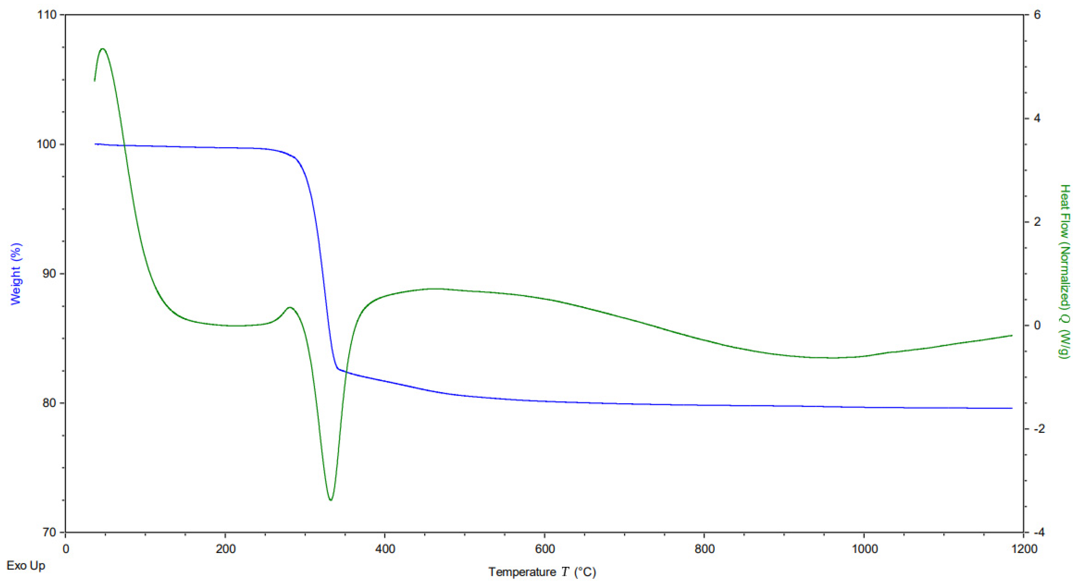
Nickel hydroxides prepared by the solvothermal method were calcinated after separation and purification to remove the residue of water after the drying process and to obtain a stable crystal structure of the oxide for catalytic application. The optimal calcination temperature was obtained from the thermal analysis conducted with sample Ni(OH)2, synthesized in conditions corresponding to the preparation of the NiOnd sample, which was used as a reference sample for this purpose. The temperature range of the analysis was 40–1200 °C (Figure 2). As can be seen on the DSC graph, the phase transformation occurs once, at about 340 degrees. The TG graph demonstrates that the sample lost about 20% of its initial mass at this temperature. XRD measurement confirmed that Ni(OH)2 was originally prepared and transformed into NiO by the described method. The analysis data correspond to the stoichiometric equation of the thermal decomposition of nickel hydroxide:
Ni(OH)2 = NiO + H2O (M(H2O)/M(Ni(OH)2) = 18 × 100%/92.7 = 19.41%).
XRD analyses (Figure S3) identified for all samples of the calcinated NiO only a single crystalline phase of NiO (100%) with a cubic structure and a spatial Group Fm-3m (PDF card 01-071-1179). The average size of coherent domains (MCL) varies from 9 to 19 nm for individual samples. The crystalline NiO phase is confirmed by diffraction peaks at the 2θ values of 43.5°, 50.5°, 74.5°, 90.5°, and 95.7°, corresponding to the characteristic diffraction of (111), (200), (220), (311), and (222) crystal planes of the NiO.

3.1. Electron Microscopy of the NiO Catalysts

3.1.1. SEM/TEM before Catalysis

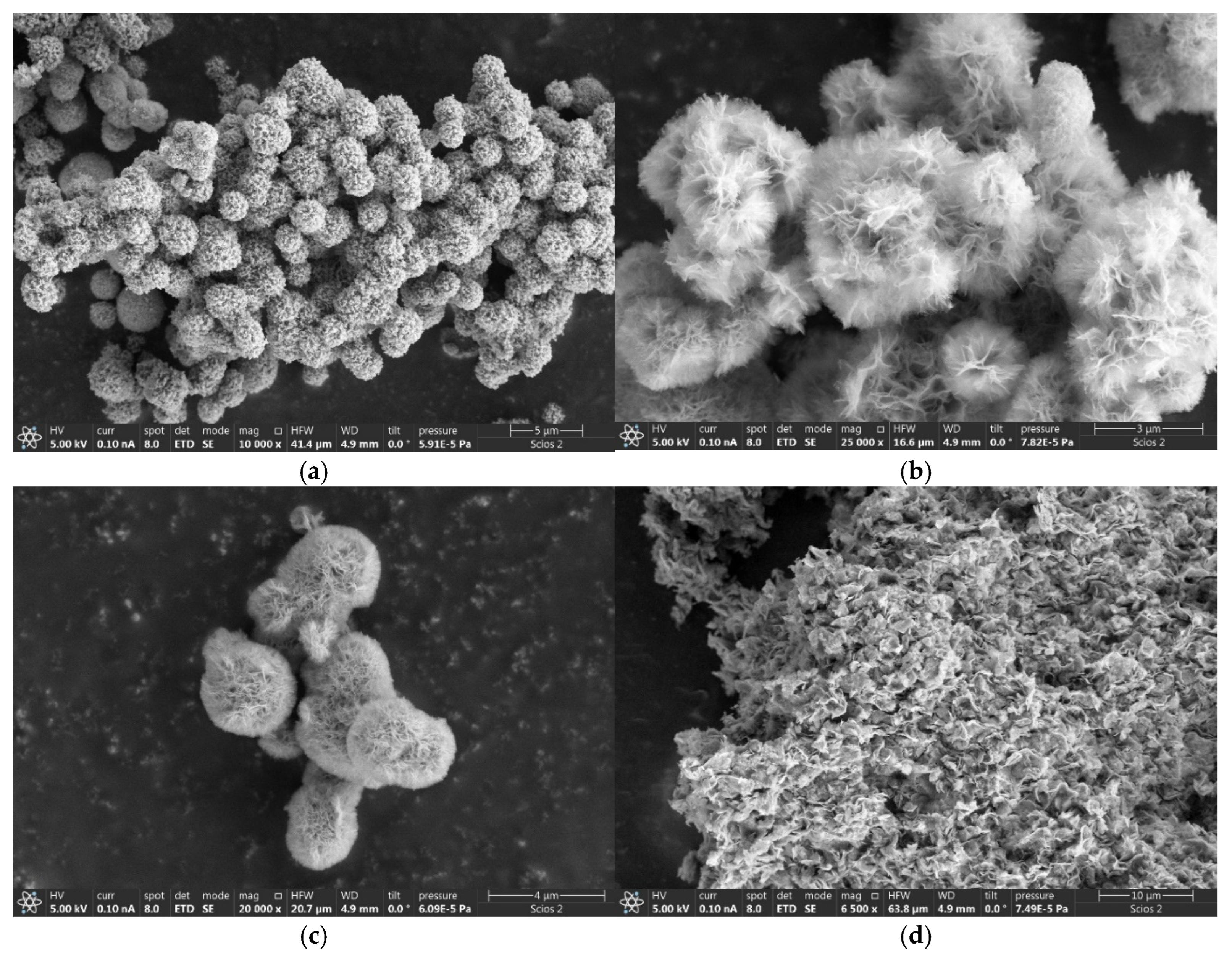
The SEM picture in Figure 3a of the NiOms1 sample shows mostly spherical microparticles of 1–3 μm in size, but shapeless ones are also found. The TEM picture (Figure S4a) shows that the spheres consist mainly of cubic crystals about 20–40 nm in size, which confirms the XRD data. SEM images in Figure 3b,c demonstrate flower-like spherical NiO MPs with a size of 1–3 μm aggregated to large clusters. However, shapeless MPs are also present in these samples. The MPs’ surface is covered with nanosheets approximately several hundred nanometers in size. In the TEM photo, it can be observed that the spheres consist of a large number of needle-like structures several hundred nanometers long and with a thickness of about 20–100 nm, which, accordingly, consist of cubic nanostructures (Figure S4b,c). The almost complete similarity of structures and sizes of MPs NiOms2 and NiOms3 is explained by identical synthesis methods; the difference is only in calcination temperature and using ultrasound during the starting part of the preparation of the NiOms3 sample. The situation in the photo (Figure 3d) is fundamentally different from previous samples: a high quantity of nanosheets with a size of about 1 micrometre are aggregated into huge clusters of tens of microns in size. Needle-like structures that are several nanometers thick and around 200 nanometers long can be traced in the TEM picture (Figure S4d). The electron microscopy observations confirmed a complete difference in morphology concerning the original article, where mesoporous microspheres were observed.
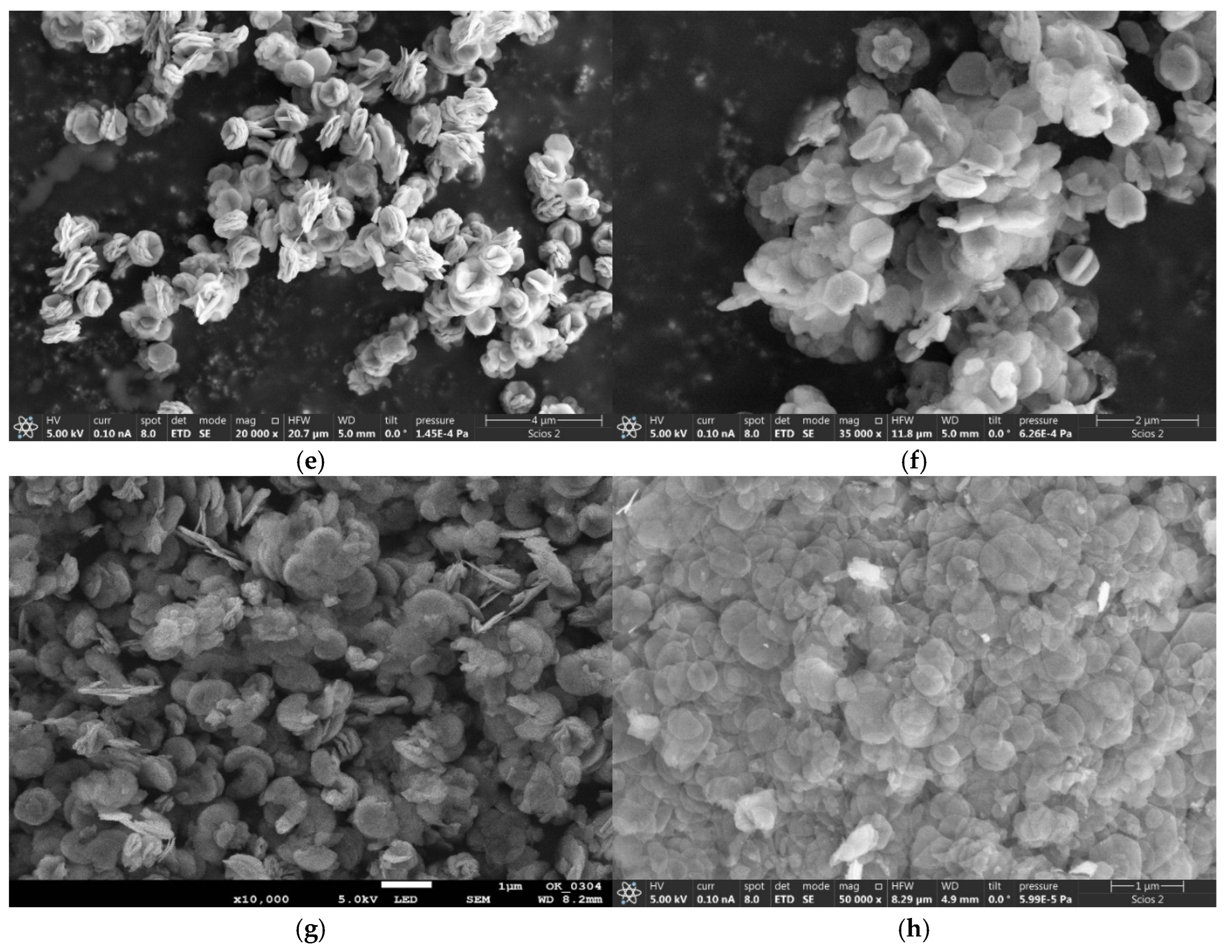
Additional preparation methods produced very similar structures, NiOhx1 and NiOhx2 (Figure 3e,f), represented by hexagonal nanoparticles of 400–600 nm in size, assembled in clusters, maybe due to the magnetism of NiO. However, NPs are visible, and the crystal faces are not coagulated together, indicating the nanoparticles’ relative stability because of using a PVP stabilizer. TEM images (Figure S4e,f) show that NPs consist of many nanocrystals, about 10 nm in size.
In Figure 3g, especially on the TEM image (Figure S4g), a large number of moon-like particles can be detected about 0.5–2 μm in size for the sample NiOhx+m. However, there are also many hexagonal structures that can be seen in the picture. NiOnd (Figure 3h) also consists of hexagonal nanodisks approximately 400–600 nm in size, which in turn consist of nanocrystals several nanometers in size, as can be observed in the TEM image (Figure S4h). However, it is clear from the SEM photo that the particles are less stable than NiOhx1 and NiOhx2 NPs and coagulate in huge clusters. It is also seen on SEM images that there are many round and shapeless fragmentary nanoparticles. As a result, it can be recognized that the hexagonal structures (NiOhx1, NiOhx2) turned out to be the most homogeneous and stable, indicating the positive role of stabilizers, as in the PVP 40,000 and 360,000.

3.1.2. SEM/TEM after Catalysis

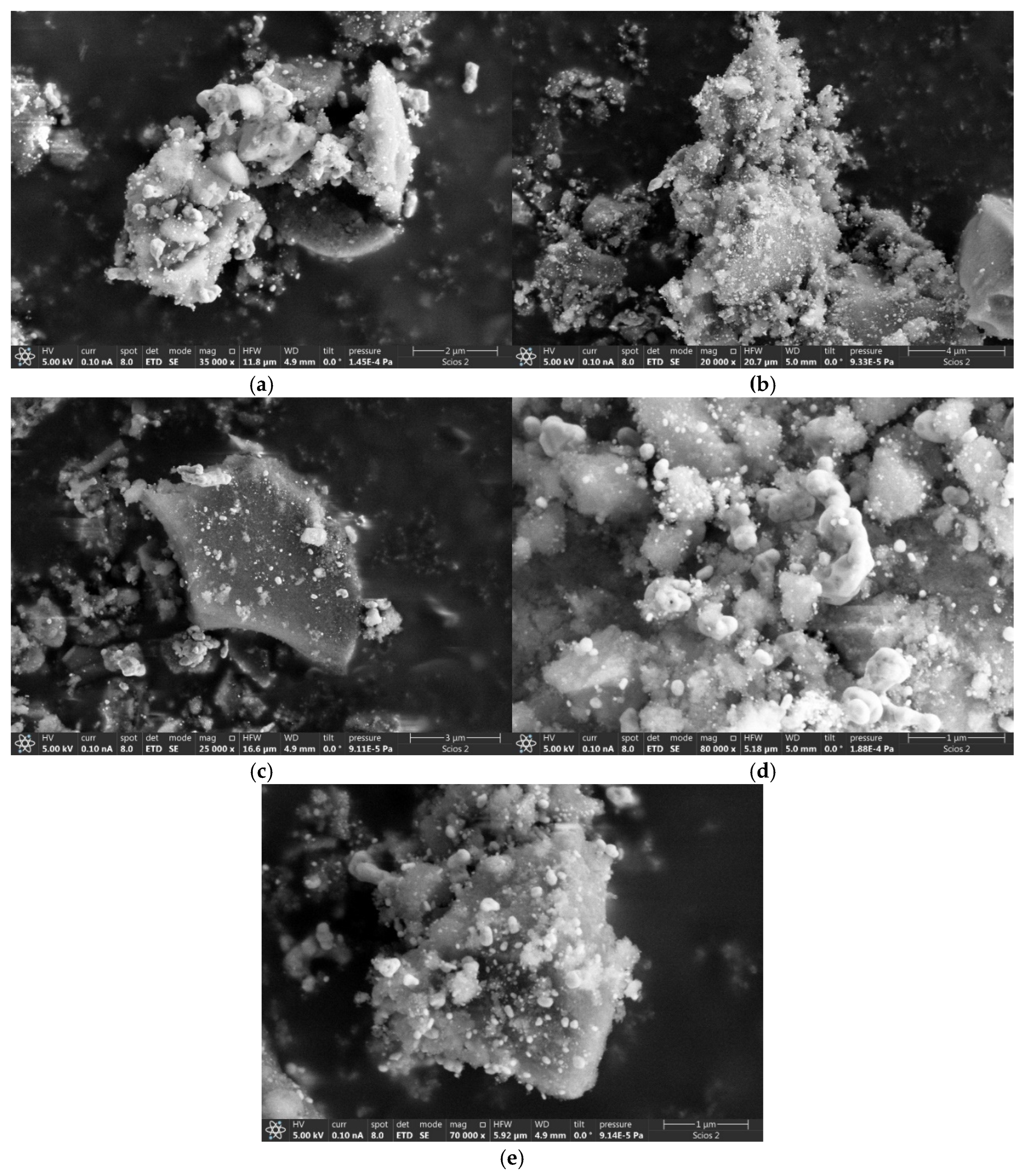
SEM images in Figure 4a–e reveal a cardinal change in the morphology of the NiO catalyst after the catalytic reaction. Amorphous, lumpy microparticles can be observed to be several microns in size, very different from the original particles before catalysis. It can be safely argued that this change is a result of the thermal stress and chemical modification of primary NiO particles during catalysis; particles lose their shape. However, spherical particles can be seen in the TEM pictures (Figure S5a,b), and hexagonal particles (Figure S5d,e), which indicates an incomplete loss of the morphology of the primary catalysts’ particles. All SEM pictures show brighter, whitish SG particles that did not participate in the catalytic reaction. They were used as indifferent supporting material to avoid the sintering of NiO catalytic particles.

3.2. Surface Area and Pore Volume Characterization

The values of the surface area (m2/g) and pore volume (cm3/g) are presented in Table 2. The NiOms1 sample has a low specific surface area—only 24.4 m2/g. The surface area of NiOms2 is about twice as high—47.7 m2/g, and NiOms3 has an essentially more developed surface—110.3 m2/g, which indicates ultrasound’s positive effect on microparticles’ surface. Despite the large clusters of particles, NiOshc demonstrates a very high surface area—103.7 m2/g, since the surface of the clusters is assembled from nano- and micro-sheets.
Samples NiOhx1 and NiOhx2 have almost the same specific surface area, which is the highest of all tested catalysts—145.5 m2/g. Sample NiOhx+m has about 10% less surface area (128.9 m2/g), indicating the appearance of many moon-like NPs. However, NiOnd has a significantly smaller specific area—55.5 m2/g, showing stronger nanoparticle clustering and adhesion.
Pore volumes of the prepared catalysts correlate to some extent with the values of their specific surface areas. The catalysts NiOms1, NiOms2, and NiOnd have the lowest values, the same as in the case of the surface area. Sample NiOhx1 has a much larger pore volume than sample NiOhx2 by about 30%, which indicates the positive effect of PVP 40,000 on pore volume. However, with a slight change in the synthesis conditions of NiOhx+m, the pore volume decreased significantly more than the surface area—from 0.22 to 0.16 cm3/g. The best value for pore volume from samples with spherical morphology was observed for NiOms3 at a value of 0.2 cm3/g, which can be explained by the influence of using ultrasound at the early stage of the preparation process. Graphs of measured isotherms are presented in Figure S6.

3.3. X-ray Photoelectron Spectroscopy

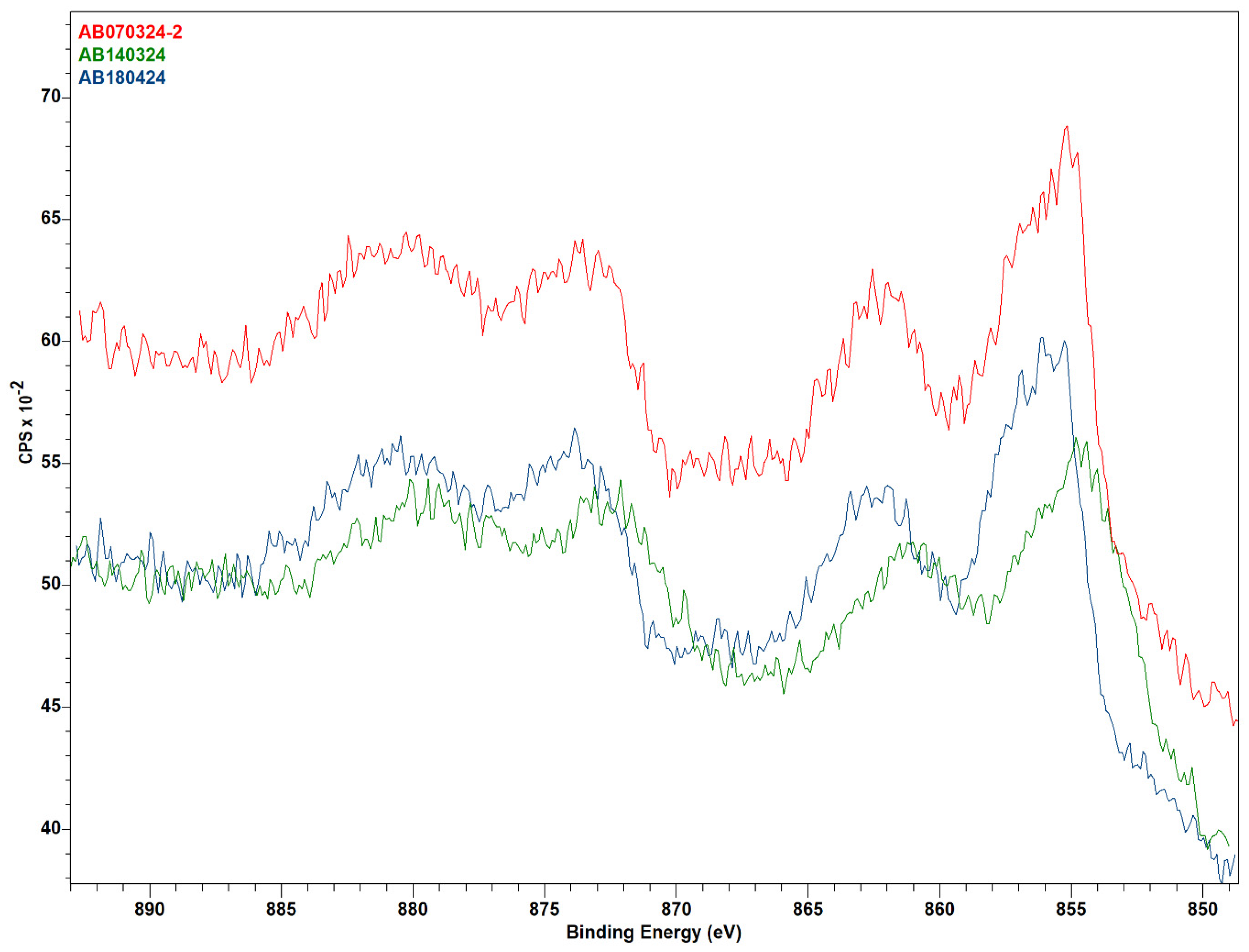
The XPS analysis (Figure 5) showed that the pre-catalysis samples have appreciable nickel content to record hi-res spectra, and there is a marked difference in NiOms1 compared to the other two. Peak fitting was attempted by assuming the nickel species present to be some mixture of NiO and Ni(OH)2, but the fitting was not fully successful. However, a conclusion can still be drawn from the difference in the spectra. As can be observed, the spectrum of sample NiOms1 is red-shifted off the other two, which certainly means that there is more NiO in this sample than in the other two. Sample NiOms1 was prepared after calcination at 450 °C, and the other two were calcinated at only 350 °C, which can result in a slightly larger amount of undecomposed nickel hydroxide on the surface of the catalyst. However, with all this, the catalytic efficiency of the sample NiOms1 in the CO2 hydrogenation was the worst.
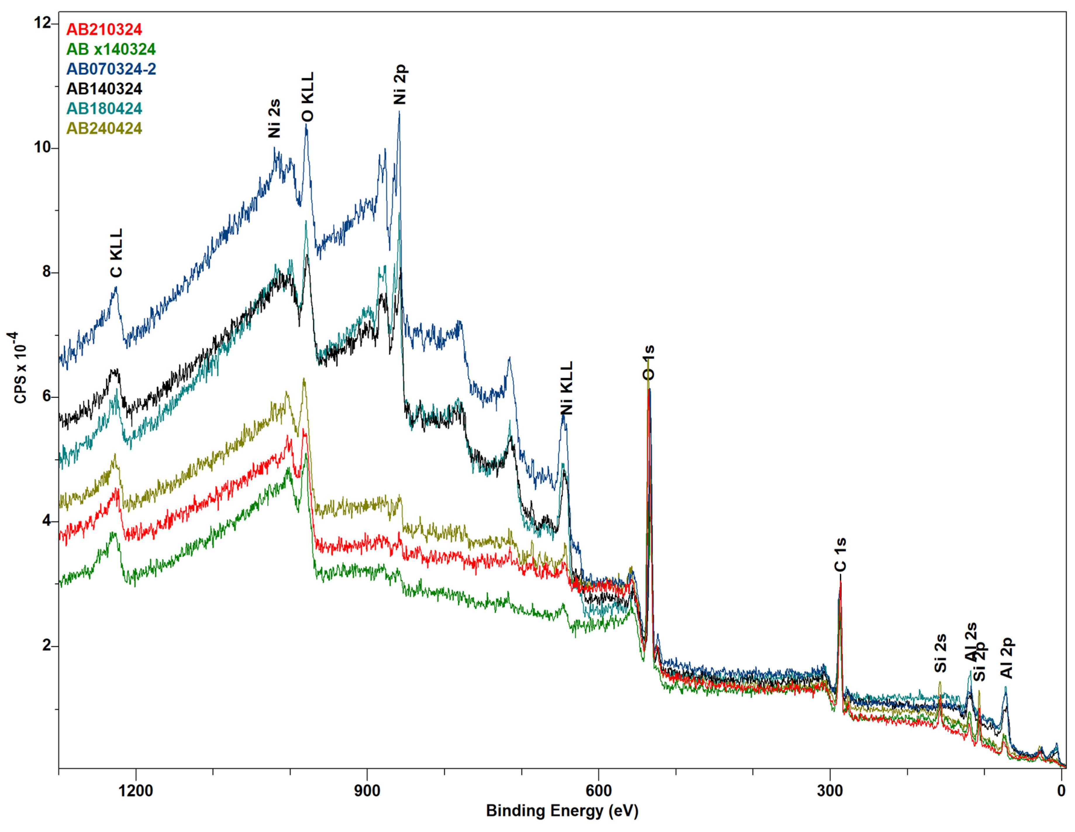
As can be seen in Figure 6 and Table 3, the XPS analysis indicated that the post-catalysis samples show small (detection-limit-adjacent) nickel content, which might stem from leaching of the metal during the reaction or, more likely, the buildup of a (mostly carbon and oxygen) “coating” on the catalyst (info depth of XPS is 5–10 nm). Really, significant differences in the spectra of all three samples, which can clarify differences in their catalytic activity, were observed after the subtraction of SiO2 content, which was used as an anti-sintering agent in a mixture with active catalysts. Unfortunately, the dilution of the catalysts in this inert material did not allow for the measurement of Ni’s high-resolution spectra for samples after catalysis.

3.4. TPR-TPD Characterization

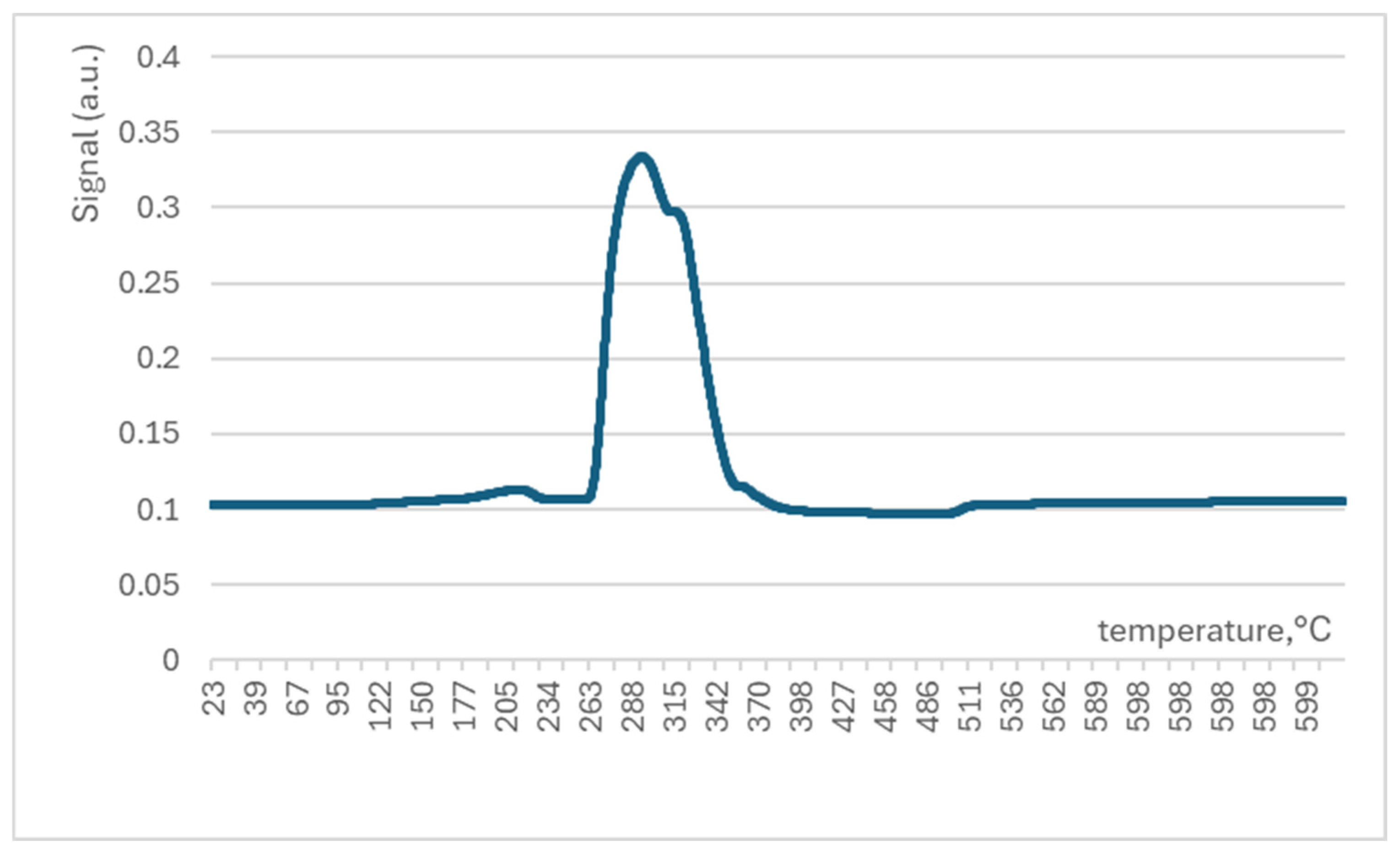
The TPR experiment for sample NiOhx2 is presented in Figure 7, where it is possible to see the features of the interaction of nickel oxide with hydrogen. A single peak indicates the reduction of nickel oxide to pure nickel at about 300 °C. Notably, all catalysts were activated at this temperature. Therefore, reduced nickel can be supposed as the starting form of the catalyst in the reactor during the catalytic stability study.
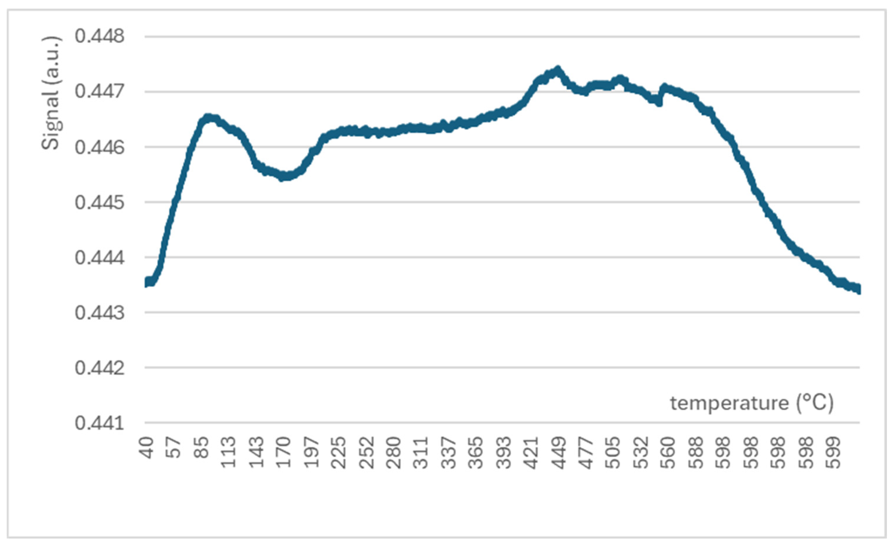
The TPD spectrum of the same sample is presented in Figure 8. Here, the sorption–desorption behaviour of carbon dioxide on the surface of the catalyst can be observed. The first adsorption signal is observed at about 100 °C. However, it is quickly followed by strong desorption, reaching a minimum at about 170 °C. After that, the adsorption signal of CO2 is raised slowly with a maximum of 450 °C. This temperature was selected as optimal for catalytic experiments also on the basis of the initial catalytic study with a temperature ramp. It is interesting that the adsorption of CO2 is stable from this point up to 600 °C and then steeply goes down. This behaviour indicates the chemisorption of CO2 on the surface of NiO-based catalysts opposite to adsorption at a lower temperature (100–170 °C), which is complementary with the mechanism of the physisorption.

3.5. Catalytic Reduction of CO2 on Different Morphologies of NiO-Based Catalysts

3.5.1. NiO Disc Structures

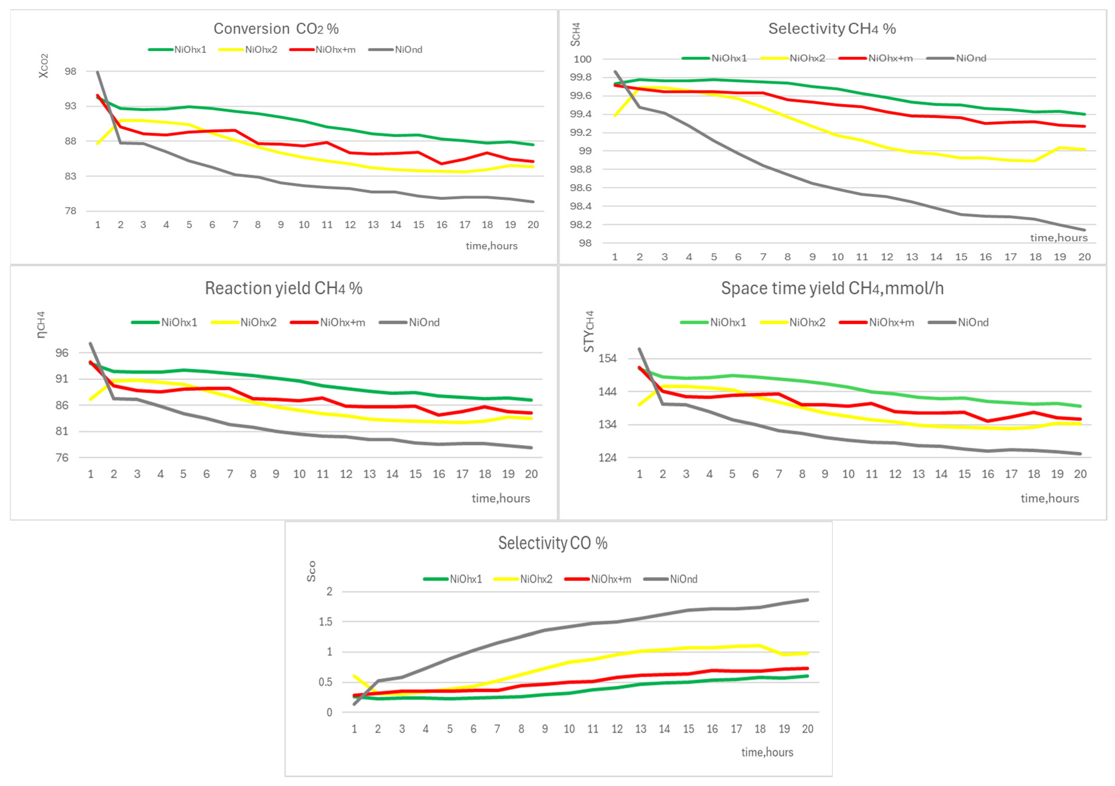
The disc structure of NiO catalyst nanoparticles is predominant in the samples NiOhx1, NiOhx2, NiOhx+m, and NiOnd. The conversion values x C O 2 dropped for all four samples during catalytic stability experiments, during all the 20 h experiments (see Figure 9), but the extension in this change is different for these samples. The strongest drop (more than 18%) was observed for the sample NiOnd. The total decrease was from 97.9 (t = 1 h) to 79.3% (t = 20 h), with the steepest decrease of 10% during the first 2 h of the catalytic experiment. The other three structures from this group showed a nearly linear decrease in x C O 2 around or less than 10% for the time of the catalytic experiment (20 h) from the starting value of around 90%.
All samples demonstrated excellent selectivity for the production of methane ( s C H 4 ) throughout the experiment—more than 98%. The decrease in this value during the experiment was for particular catalysts as follows: NiOhx1—from 99.8 (t = 2 h) to 99.4% (t = 20 h); NiOhx2—from 99.7 (t = 2 h) to 99.0% (t = 20 h); NiOhx+m—from 99.7 (t = 1 h) to 99.3% (t = 20 h); and NiOnd—from 99.9 (t = 1 h) to 98.1% (t = 20 h). The values of x C O 2 obtained for NiOhx1 are the best results in the selectivity and conversion of overall disc morphology catalysts. This is the sample with the highest surface area and the lowest carbon content determined by XPS. Unfortunately, the character of catalytic samples (due to dilution by SiO2) makes it impossible to detail the characterization of the Ni state in an active catalyst. However, it can be deduced indirectly from the results of these measurements that this type of morphology is the most resistant to the formation of atomic carbon deposits, which can hamper the access of CO2 molecules to the active catalytic surface and reduce, by this way, the catalytic activity of the particular catalyst.
Reaction yield ( η C H 4 ) and space–time yield ( S T Y C H 4 ) changed according to the same pattern trend as x C O 2 and s C H 4 . The curves of both characteristics look identical for all samples. A significant drop was observed for sample NiOnd: η C H 4 —from 97.8 (t = 1 h) to 77.9% (t = 20 h); and S T Y C H 4 —from 157.0 (t = 1 h) to 125.1 mmol/h (t = 20 h). The decrease in η C H 4 and S T Y C H 4 for the remaining samples was less than 10%. η C H 4 values for NiOhx1, NiOhx2, and NiOhx+m samples were higher than 80% (84–87%) at the end of the experiment. S T Y C H 4 values are also excellent, as they are in the range of 134–140 mmol/h. If we disregard the initial STY value of 157.0 mmol/h for the NiOnd catalyst, which drops sharply by about 11% to 140 mmol/h within the first two hours, then the remaining three catalysts provide significantly better results in terms of methane production. The best of these, NiOhx1, provides an STY of 151.0 mmol/h after 1 h, with a decrease to 140.0 mmol/h after 20 h of the reaction, which represents an overall decrease of only 8% compared to the NiOnd catalyst, where the decrease to 125.1 mmol/h represents a relative decrease of 17%, i.e., a value approximately twice that of the best catalyst in this group.
In all cases, the selectivity of unwanted product CO (sCO) increased slightly during catalysis (from 0 to 2%). The largest increase was found for the sample NiOnd—from 0.1 (t = 1 h) to 1.9% (t = 20 h). In the remaining samples, the maximum value of sCO at the end of the experiment was insignificant (less than 1%)
Summing up, all four catalysts with prevailed disc morphology showed excellent results for the main indicators—selectivity CH4 and conversion CO2. Only catalyst NiOnd showed worse results in the stability of the CO2 conversion and the selectivity of CH4 production. With respect to the most complicated process of its preparation, this catalyst can be marked as the less utilizable catalyst for application in real industrial conditions.

3.5.2. NiO Microsphere and Sheet-Cluster Structures

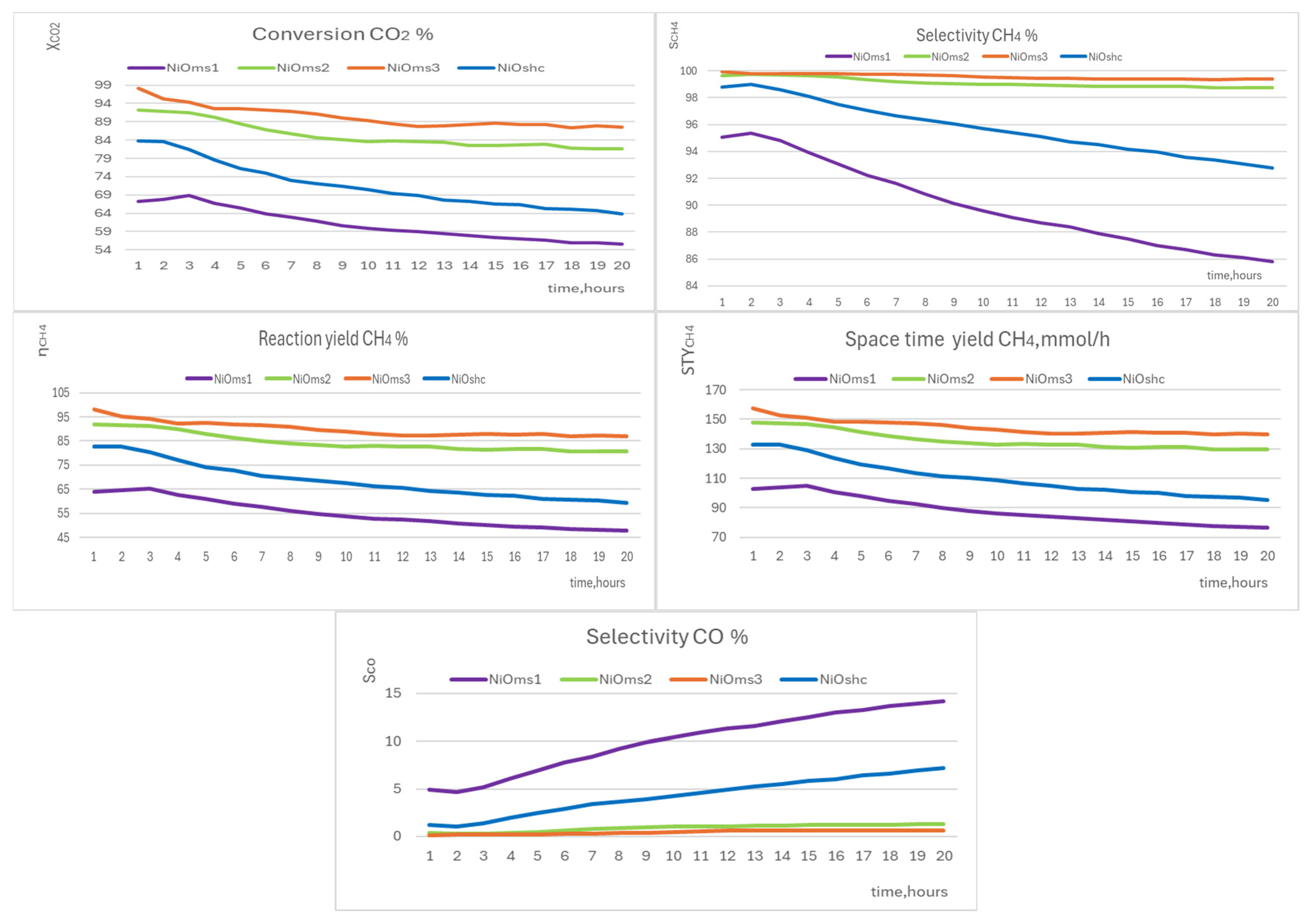
The microsphere structure of NiO catalyst nanoparticles is predominant in the samples NiOms1, NiOms2, and NiOms3, while sheet-cluster morphology was observed for sample NiOshc. All samples with these types of morphology demonstrated conversion worse than was observed for the previous group of disc morphology catalytic particles (Figure 10). In particular, catalyst NiOms1 showed the worst catalytic activity of all studied catalysts. The conversion of CO2 declined from the value of 68.9 (t = 3 h) to the value of 55.6% (t = 20 h) in this case. This very low catalytic activity can be explained by the lowest surface area from all tested catalysts and also by the highest deposits of atomic carbon (as was determined by XPS), which can act as a catalytic barrier. The other two catalysts with microsphere morphology were in the value range of CO2 conversion comparable with disc morphology catalysts—in the case of NiOms2, the value of x C O 2 declined starting from 92.3 (t = 1 h) to 81.7% (t = 20 h), and in the case of NiOms3, from 98.2 (t = 1 h) to 87.6% (t = 20 h). On the other hand, a substantial drop in the value of x C O 2 (approx. 20%) was observed for the sample NiOshc—from 83.8 (t = 1 h) to 63.8% (t = 20 h).
The selectivity of CH4 production goes down almost linearly for both of the worst catalysts, NiOms1 (from 95.3 to 85.8%) and NiOshc (from 98.8 to 92.8%). The other two catalysts showed more stable selectivity for the production of CH4; it decreased for NiOms2 from 99.7 (t = 1 h) to 98.7% (t = 20 h) and for NiOms3 from 99.9 (t = 1 h) to 99.4% (t = 20 h). Therefore, they could be selected as the best from all the studied catalysts not only from the point of view of the selectivity production of methane but also from the point of view of S T Y C H 4 values (see below).
Reaction yield CH4 ( η C H 4 ) for NiOms1 significantly dropped from 65.4 (t = 3 h) to 47.7% (t = 20 h) and for NiOshc from 82.8 (t = 1 h) to 59.2% (t = 20 h). For NiOms2 and NiOms3 samples, η C H 4 dropped a bit more than 10%; for NiOms2, it dropped from 91.9 (t = 1 h) to 80.6% (t = 20 h) and for NiOms3 from 98.1 (t = 1 h) to 87.0% (t = 20 h). S T Y C H 4 changed in all four samples in a similar way, but for the two worst catalysts, the decrease in this value with time is more considerable. The biggest drop was observed for the NiOms1 catalyst, from 105.0 (t = 3 h) to 76.6 mmol/h (t = 20 h), and also for the second worst catalyst, the NiOshc decrease was considerable as S T Y C H 4 was changed from 132.9 (t = 1 h) to 95.0 mmol/h (t = 20 h). On the other hand, the two best catalysts in this group, NiOms2 and NiOms3, showed 157.5 mmol/h (NiOms3) or 147.6 mmol/h (NiOms2) at the start reaction with a slow decrease of about 10% (140 mmol/h for NiOms3 after 20 h) or 12% (130 mmol/h for NiOms2 after 20 h).
Selectivity CO increased very much for NiOms1, from 4.9 (t = 1 h) to 14.2% (t = 20 h). NiOms2 and NiOms3 showed non-important increases in sCO from 0.3 (t = 2 h) to 1.3% (t = 20 h, NiOms2) and from 0.1 (t = 1 h) to 0.6% (t = 20 h, NiOms3). In the case of NiOshc, which is the second worst catalyst from all those tested, sCO increased much more from 1.0 (t = 2 h) to 7.2% (t = 20 h).
To sum up, the two best catalysts from this group are those prepared in the DMF solution—NiOms2 and NiOms3. Due to the strong drop in conversion CO2 for catalysts NiOms1 and NiOshc, industrial use of catalysts does not seem promising.

3.5.3. Comparison of Catalytic Activity of Prepared NiO Structures

The solvothermal method used for the preparation of the NiO catalyst showed good variability in the morphology of the prepared catalysts by simply changing the used solvent and alternatively using a polymer stabilizing agent. The results obtained from the catalytic activity of these NiO-based catalysts are very good in comparison with those of more sophisticated catalysts in Table 4. The presented data clearly show that simple NiO-based catalysts with optimal morphology can produce methane with efficiency comparable to Ni catalysts modified or supported by the more valuable metals prepared using more complicated and time-consuming methods. The only disadvantage of the newly prepared catalysts is that their optimal catalytic activity requires a relatively high temperature of 450 °C, which increases the energy consumption of the catalytic process in practise. However, the simple composition of the catalyst offers future possibilities to optimize the reaction temperature, e.g., by modification with active support instead of the simple dilution of the NiO catalyst by the inert micro-SiO2.
The observed high catalytic activity of the prepared pure NiO catalyst does not only come from their high specific surface area, which is more than about 140 m2/g for the best catalysts NiOhx1, NiOhx2, and NiOhx+m and 110 m2/g for NiOms2 and NiOms3. Another important property is given by the nature of their nanostructured surface, thanks to which, in the activation phase, NiO can be partially transformed into metallic Ni, which is essential in terms of the activation of hydrogen molecules for their own reaction with the carbon dioxide molecule [57]. The resulting metallic nickel nanoparticles are also detectable in XPS spectra. Here, it can be seen that for active catalysts, there is a signal of metal Ni in the spectrum at the energy level of 852.5 eV. Unfortunately, this signal is not well quantifiable due to the low concentration of Ni in the used catalyst caused by the use of SiO2 as an auxiliary material. On the other hand, the gentle decrease in the catalyst activity observed during the tests cannot be ascribed to the formation of the carbon deposits on the surface of the catalysts as neither XPS spectra nor SEM images in the secondary electron mode (see Figure S7) proved the existence of relevant carbon deposits.
Table 4. The basic results of the catalytic action of the prepared catalysts compared with the literature data.
CatalystReaction Temperature (°C) x C O 2 (%) s C H 4 Ref.
NiOms34509199this work
NiOhx14509199this work
La-doped Ni/SiO22757199[58]
Ni/Y2O33405560[59]
Ni/Y2O330092100[60]
Ni/ITQ6 zeolite4507998[61]
Ni/MgO2757998[62]
Ni/CeO24008098[63]
Ni/CeO242094100[64]
Ni/perovskite4256198[65]

4. Conclusions

Based on the experiments conducted, the following important conclusions can be drawn:
  • Catalysts prepared by simple solvothermal methods using inexpensive and green solvents (water, ethanol), namely NiOhx1, NiOhx2, and NiOhx+m, demonstrated excellent catalytic activity in CO2 methanation, especially due to their well-developed surface area (145 m2/g) and good resistance to blocking of the active catalyst area by deposits of atomic carbon, which is a problem of many methanation catalysts.
  • NiO catalytic samples prepared using the solvothermal method in the DMF solvent (NiOms2 and NiOms3) also showed very good catalytic activity, especially NiOms3, since it has a more developed surface (110 m2/g), which may be due to the use of ultrasound in synthesis. However, the use of an expensive DMF and not green solvent and a long reaction time make the preparation of this catalyst more expensive than the preparation of the above-mentioned disc structures.
  • NiOnd, NiOms1, and NiOshc are very poor catalysts due to a high drop in methane conversion and methane selectivity during the catalytic reaction (20 h). The results of XPS measurements also indicate lower resistance of these structures against deposits of atomic carbon during the reaction course. This fact is probably the main reason for the observed time instability of the catalytic efficiency of these catalysts. Therefore, the modifications of the solvothermal method used for the preparation of these catalysts are not promising for advanced studies.

Supplementary Materials

The following supporting information can be downloaded at: https://www.mdpi.com/article/10.3390/molecules29204838/s1, Figure S1: Comparison of the experimental and equilibrium values for the methanation of CO2 obtained in the test experiment with NiOhx1 sample. Figure S2: Diagram describing temperature change with time during catalytic experiments. Figure S3: XRD patterns of NiO pre-catalysts (CoKa-radiation). Figure S4: TEM images of NiO pre-catalysts. Figure S5: TEM images of NiO samples after catalysis. Figure S6: Isotherm plot and BET surface area plot diagrams of NiO pre-catalysts. Figure S7: SEM images of the spent catalyst samples obtained in secondary electrons mode.

Author Contributions

Conceptualization, A.B., A.P. and L.K.; Methodology, A.B., T.S., M.K., R.P., Z.E. and L.K.; Validation, R.P., Z.E. and L.K.; Formal analysis, A.B., T.S., M.K., Z.K., J.K., A.P., T.F., C.C., Z.E. and L.K.; Investigation, A.B., T.S., Z.K., J.K., T.F. and C.C.; Data curation, A.P. and L.K.; Writing—original draft, A.B. and L.K.; Writing—review & editing, A.B., T.S., M.K., Z.K., J.K., R.P., A.P., T.F., C.C., Z.E. and L.K.; Supervision, L.K.; Funding acquisition, R.P., Z.E. and L.K. All authors have read and agreed to the published version of the manuscript.

Funding

The authors acknowledge financial support from the ERDF project “Development of pre-applied research in nanotechnology and biotechnology” (No. CZ.02.1.01/0.0/0.0/17_048/0007323); project Research Infrastructure NanoEnviCz, supported by the Ministry of Education, Youth and Sports of the Czech Republic (No. LM2023066); project TKP2021-NKTA-34 with the support provided from the National Research, Development and Innovation Fund of Hungary, financed under the TKP2021-NKTA funding scheme; and Internal Grant of Palacký University, grant number IGA_Prf_2024_021.

Institutional Review Board Statement

Not applicable.

Informed Consent Statement

Not applicable.

Data Availability Statement

The original contributions presented in the study are included in the article/Supplementary Material, further inquiries can be directed to the corresponding author.

Acknowledgments

The authors acknowledge Klára Čépe, Jana Stráská, and Eirini Ioannou for TEM and SEM characterizations of the prepared catalysts and Alexandra Rancová for the determination of the surface area of the catalysts by BET.

Conflicts of Interest

The authors declare no conflicts of interest. The funders had no role in the study’s design; in the collection, analyses, or interpretation of the data; in the writing of the manuscript; or in the decision to publish the results.

References

  1. Chen, Z.M.; Xie, W.; Zhang, H.Y. Error of acid rain research, effect of atmosphere CO2 ignored. Prog. Environ. Sci. Eng. 2013, 610–613, 381–384. [Google Scholar] [CrossRef]
  2. Mirica, M. Carbon Dioxide Pollution when Burning Solid, Liquid and Gas Fuels. Rev. Chim. 2011, 62, 947–949. [Google Scholar]
  3. Yang, X.H.; Jin, X.B.; Zhou, Y.K. Carbon emissions induced by farmland expansion in China during the past 300 years. Sci. China Earth Sci. 2019, 62, 423–437. [Google Scholar] [CrossRef]
  4. Li, H.S.B.; Ye, Y.; Li, H.X.; Ye, Q. Emergence, distribution dynamics and drivers of global high-emission countries since the Industrial Revolution. Int. J. Glob. Warm. 2023, 29, 383–394. [Google Scholar] [CrossRef]
  5. Ghommem, M.; Hajj, M.R.; Puri, I.K. Influence of natural and anthropogenic carbon dioxide sequestration on global warming. Ecol. Model. 2012, 235–236, 1–7. [Google Scholar] [CrossRef]
  6. Constantin, F.A.; Loredana, I. The Causes and Effects of Global Warming. In Proceedings of the 9th International Multidisciplinary Scientific GeoConference (Sgem 2009), Albena, Bulgaria, 14–19 June 2009; Volume I, pp. 147–154. [Google Scholar]
  7. Zhu, S.S.; Sun, H.; Xia, X.C.; Yang, Z.D. Decoupling Analysis of Carbon Emissions and Forest Area in China from 2004 to 2020. Land 2023, 12, 1458. [Google Scholar] [CrossRef]
  8. Wang, Y.P.; Galbally, I.E.; Meyer, C.P.; Smith, C.J. A comparison of two algorithms for estimating carbon dioxide emissions after forest clearing. Environ. Model. Softw. 1997, 12, 187–195. [Google Scholar] [CrossRef]
  9. Carvalho, J.A.; Santos, J.M.; Santos, J.C.; Leitao, M.M. A Tropical Rain-Forest Clearing Experiment by Biomass Burning in the Manaus Region. Atmos. Environ. 1995, 29, 2301–2309. [Google Scholar] [CrossRef]
  10. Carbon Capture and Storage Plant Becomes Operational in Iceland; UNESCO: Paris, France, 2021; Available online: https://www.unesco.org/en/articles/carbon-capture-and-storage-plant-becomes-operational-iceland (accessed on 6 April 2024).
  11. World’s Biggest Machine Capturing Carbon from Air Turned on in Iceland; Agence France-Presse: Paris, Frence, 2021; Available online: https://www.theguardian.com/environment/2021/sep/09/worlds-biggest-plant-to-turn-carbon-dioxide-into-rock-opens-in-iceland-orca (accessed on 26 December 2021).
  12. The ‘World’s Largest’ Vacuum to Suck Climate Pollution out of the Air Just Opened. Here’s How It Works; CNN: Atlanta, GA, USA, 2024.
  13. Jiang, L.; Liu, W.; Wang, R.; Gonzalez-Diaz, A.; Rojas-Michaga, M.F.; Michailos, S.; Pourkashanian, M.; Zhang, X.; Font-Palma, C. Sorption direct air capture with CO2 utilization. Prog. Energy Combust. Sci. 2023, 95, 101069. [Google Scholar] [CrossRef]
  14. Ignatusha, P.; Lin, H.Q.; Kapuscinsky, N.; Scoles, L.; Ma, W.G.; Patarachao, B.; Du, N.Y. Membrane Separation Technology in Direct Air Capture. Membranes 2024, 14, 30. [Google Scholar] [CrossRef]
  15. Lino, A.V.P.; Assaf, E.M.; Assaf, J.M. Production of light hydrocarbons at atmospheric pressure from CO2 hydrogenation using CexZr(1-x)O2 iron-based catalysts. J. CO2 Util. 2022, 55, 101805. [Google Scholar] [CrossRef]
  16. To, A.T.; Arellano-Treviño, M.A.; Nash, C.P.; Ruddy, D.A. Direct synthesis of branched hydrocarbons from CO2 over composite catalysts in a single reactor. J. CO2 Util. 2022, 66, 102261. [Google Scholar] [CrossRef]
  17. Cui, L.R.; Liu, C.; Yao, B.Z.; Edwards, P.P.; Xiao, T.C.; Cao, F.H. A review of catalytic hydrogenation of carbon dioxide: From waste to hydrocarbons. Front. Chem. 2022, 10, 1037997. [Google Scholar] [CrossRef] [PubMed]
  18. Van der Laan, G.P.; Beenackers, A.A.C.M. Kinetics and selectivity of the Fischer-Tropsch synthesis: A literature review. Catal. Rev. Sci. Eng. 1999, 41, 255–318. [Google Scholar] [CrossRef]
  19. Sie, S.T. Process development and scale up: IV. Case history of the development of a Fischer-Tropsch synthesis process. Rev. Chem. Eng. 1998, 14, 109–157. [Google Scholar] [CrossRef]
  20. Tsubaki, N.; Fujimoto, K. Product control in Fischer-Tropsch synthesis. Fuel Process. Technol. 2000, 62, 173–186. [Google Scholar] [CrossRef]
  21. Zhang, Q.H.; Kang, J.C.; Wang, Y. Development of Novel Catalysts for Fischer-Tropsch Synthesis: Tuning the Product Selectivity. ChemCatChem 2010, 2, 1030–1058. [Google Scholar] [CrossRef]
  22. Fujita, S.I.; Takezawa, N. Difference in the selectivity of CO and CO2 methanation reactions. Chem. Eng. J. 1997, 68, 63–68. [Google Scholar] [CrossRef]
  23. Griboval-Constant, A.; Butel, A.; Ordomsy, V.V.; Chernavskii, P.A.; Khodakova, A.Y. Cobalt and iron species in alumina supported bimetallic catalysts for Fischer-Tropsch reaction. Appl. Catal. A Gen. 2014, 481, 116–126. [Google Scholar] [CrossRef]
  24. Romar, H.; Lahti, R.; Tynjälä, P.; Lassi, U. Co and Fe Catalysed Fischer-Tropsch Synthesis in Biofuel Production 14th Nordic Symposium on Catalysis. Top. Catal. 2011, 54, 1302. [Google Scholar] [CrossRef]
  25. Strysovsky, T.; Kajabová, M.; Prucek, R.; Panacek, A.; Simkovicova, K.; Vajda, S.; Kvitek, L. Temperature switching of product selectivity in CO2 reduction on Cu/In2O3 catalysts. J. CO2 Util. 2023, 77, 102617. [Google Scholar] [CrossRef]
  26. Nie, X.W.; Li, W.H.; Jiang, X.; Guo, X.W.; Song, C.S. Recent advances in catalytic CO2 hydrogenation to alcohols and hydrocarbons. Adv. Catal. 2019, 65, 121–233. [Google Scholar] [CrossRef]
  27. Rahdar, A.; Aliahmad, M.; Azizi, Y. NiO Nanoparticles: Synthesis and Characterization. J. Nanostruct. 2015, 5, 145–151. [Google Scholar] [CrossRef]
  28. Nobakht, A.R.; Rezaei, M.; Alavi, S.M.; Akbari, E.; Varbar, M.; Hafezi-Bakhtiari, J. CO2 methanation over NiO catalysts supported on CaO-Al2O3: Effect of CaO:Al2O3 molar ratio and nickel loading. Int. J. Hydrogen Energy 2023, 48, 38664–38675. [Google Scholar] [CrossRef]
  29. Zhu, W.L.; Shui, A.Z.; Xu, L.F.; Cheng, X.S.; Liu, P.G.; Wang, H. Template-free sonochemical synthesis of hierarchically porous NiO microsphere. Ultrason. Sonochem. 2014, 21, 1707–1713. [Google Scholar] [CrossRef]
  30. Aslani, A.; Oroojpour, V.; Fallahi, M. Sonochemical synthesis, size controlling and gas sensing properties of NiO nanoparticles. Appl. Surf. Sci. 2011, 257, 4056–4061. [Google Scholar] [CrossRef]
  31. Yang, Q.; Sha, J.; Ma, X.Y.; Yang, D.R. Synthesis of NiO nanowires by a sol-gel process. Mater. Lett. 2005, 59, 1967–1970. [Google Scholar] [CrossRef]
  32. Jeevanandam, P.; Pulimi, V.R.R. Synthesis of nanocrystalline NiO by sol-gel and homogeneous precipitation methods. Indian J. Chem. 2012, 51A, 586–590. [Google Scholar]
  33. Li, X.L.; Zhang, X.X.; Li, Z.R.; Qian, Y.T. Synthesis and characteristics of NiO nanoparticles by thermal decomposition of nickel dimethylglyoximate rods. Solid State Commun. 2006, 137, 581–584. [Google Scholar] [CrossRef]
  34. Mehdizadeh, R.; Sanati, S.; Saghatforoush, L.A. Preparation and Characterization of Nickel Oxide Nanostructures via Solid State Thermal Decomposition Approach. Synth. React. Inorg. Met. Org. Nano Met. Chem. 2013, 43, 466–470. [Google Scholar] [CrossRef]
  35. Chandrakala, M.; Raj Bharath, S.; Maiyalagan, T.; Arockiasamy, S. Synthesis, crystal structure and vapour pressure studies of novel nickel complex as precursor for NiO coating by metalorganic chemical vapour deposition technique. Mater. Chem. Phys. 2017, 201, 344–353. [Google Scholar] [CrossRef]
  36. Ansar, A.; Soysal, D.; Schiller, G. Nanostructured functional layers for solid oxide fuel cells. Int. J. Energy Res. 2009, 33, 1191–1202. [Google Scholar] [CrossRef]
  37. Razali, M.H.; Buang, N.A.; Bakar, W.A.W.A. CO2/H2 Methanation Reactivity of Nickel Oxide Based Catalyst Prepared from Different Nickel Salt Precursors. In Proceedings of the International Conference On Advancement Of Materials And Nanotechnology (ICAMN—2007), Langkawi, Malaysia, 29 May–1 June 2009; pp. 195–199. [Google Scholar] [CrossRef]
  38. Xu, J.; Wang, M.R.; Liu, Y.Y.; Li, J.; Cui, H.T. One-pot solvothermal synthesis of size-controlled NiO nanoparticles. Adv. Powder Technol. 2019, 30, 861–868. [Google Scholar] [CrossRef]
  39. Chen, T.; Yang, Y.; Zhao, W.Y.; Pan, D.Q.; Zhu, C.T.; Lin, F.Y.; Guo, X.Y. Solvothermal Preparation and Characterization of Nano-nickel Oxide. Acta Chim. Sin. 2019, 77, 447–454. [Google Scholar] [CrossRef]
  40. Zhang, Q.; Liu, H.X.; Li, H.L.; Liu, Y.; Zhang, H.Y.; Li, T.D. Solvothermal synthesis and photocatalytic properties of NiO ultrathin nanosheets with porous structure. Appl. Surf. Sci. 2015, 328, 525–530. [Google Scholar] [CrossRef]
  41. Poimenidis, I.A.; Lykaki, M.; Moustaizis, S.; Loukakos, P.; Konsolakis, M. One-step solvothermal growth of NiO nanoparticles on nickel foam as a highly efficient electrocatalyst for hydrogen evolution reaction. Mater. Chem. Phys. 2023, 305, 128007. [Google Scholar] [CrossRef]
  42. Kajabova, M.; Strysovsky, T.; Bikbashev, A.; Kovarova, Z.; Simkovicova, K.; Prucek, R.; Panacek, A.; Novak, P.; Kopp, J.; Kaslik, J.; et al. Electron traps as a valuable criterium of iron oxide catalysts’ performance in CO2 hydrogenation. J. CO2 Util. 2024, 85, 102863. [Google Scholar] [CrossRef]
  43. Jalama, K.; Coville, N.J.; Hildebrandt, D.; Glasser, D.; Jewell, L.L. Fischer-Tropsch synthesis over Co/TiO2: Effect of ethanol addition. Fuel 2007, 86, 73–80. [Google Scholar] [CrossRef]
  44. Kwak, B.S.; Choi, B.H.; Ji, M.J.; Park, S.M.; Kang, M. Synthesis of spherical NiO nanoparticles using a solvothermal treatment with acetone solvent. J. Ind. Eng. Chem. 2012, 18, 11–15. [Google Scholar] [CrossRef]
  45. Zhao, B.; Ke, X.K.; Bao, J.H.; Wang, C.L.; Dong, L.; Chen, Y.W.; Chen, H.L. Synthesis of Flower-Like NiO, Effects of Morphology on Its Catalytic Properties. J. Phys. Chem. 2009, 113, 14440–14447. [Google Scholar] [CrossRef]
  46. Zhou, D.S.; Yan, A.F.; Wu, Y.; Wu, T.H. A facile synthetic route to flower-like NiO and its catalytic properties. Indian J. Chem. 2013, 52A, 51–56. [Google Scholar]
  47. NassBarakat, A.M.; Abdelkareem, M.A.; El-Newehy, M.; Kim, H.Y. Influence of the nanofibrous morphology on the catalytic activity of NiO nanostructures: An effective impact toward methanol electrooxidation. Nanoscale Res. Lett. 2013, 8, 402. [Google Scholar] [CrossRef]
  48. Silva, V.D.; Simoes, T.A.; Grilo, J.P.F.; Medeiros, E.S.; Macedo, D.A.; Macedo, D.A. Impact of the NiO nanostructure morphology on the oxygen evolution reaction catalysis. J. Mater. Sci. 2020, 55, 6648–6659. [Google Scholar] [CrossRef]
  49. Bai, G.; Dai, H.; Deng, J.; Liu, Y.; Ji, K. Porous NiO nanoflowers and nanourchins: Highly active catalysts for toluene combustion. Catal. Commun. 2012, 27, 148–153. [Google Scholar] [CrossRef]
  50. Xiao, J.; Chen, B.; Liang, X.; Zhang, R.; Li, Y. NiO microspheres with tunable porosity and morphology effects for CO oxidation. Catal. Sci. Technol. 2011, 1, 999–1005. [Google Scholar] [CrossRef]
  51. Wang, J.; Wei, C.; Pang, H.; Gao, F.; Yin, J.; Guan, L.; Lu, Q. Facile synthesis of mono-dispersive hierarchical nickel-based microspheres as potential catalysts. Catal. Commun. 2011, 12, 1031–1036. [Google Scholar] [CrossRef]
  52. San, X.; Wang, G.; Liang, B.; Ma, J.; Meng, D.; Shen, Y. Flower-like NiO hierarchical microspheres self-assembled with nanosheets: Surfactant-free solvothermal synthesis and their gas sensing properties. J. Alloys Compd. 2015, 636, 357–362. [Google Scholar] [CrossRef]
  53. Kumar, S.; Das, J. Synthesis, structural and magnetic properties of NiO nanospheres and rGO-NiO nanocomposites and observing magnetocaloric effect in rGO-NiO nanocomposites. Mater. Sci. Eng. B 2021, 265, 115007. [Google Scholar] [CrossRef]
  54. Abbasa, S.A.; Junga, K.-D. Preparation of mesoporous microspheres of NiO with high surface area and analysis on their pseudocapacitive behavior. Electrochim. Acta 2016, 193, 145–153. [Google Scholar] [CrossRef]
  55. Su, C.; Zhang, L.; Han, Y.; Ren, C.; Chen, X.; Hu, J.; Zeng, M.; Hu, N.; Su, Y.; Zhou, Z.; et al. Controllable synthesis of crescent-shaped porous NiO nanoplates for conductometric ethanol gas sensors. Sens. Actuators B Chem. 2019, 296, 126642. [Google Scholar] [CrossRef]
  56. Wang, J.; Pang, H.; Yin, J.; Guan, L.; Lu, Q.; Gao, F. Controlled fabrication and property studies of nickel hydroxide and nickel oxide nanostructures. CrystEngComm 2010, 12, 1404–1409. [Google Scholar] [CrossRef]
  57. Zhu, J.; Cannizzaro, F.; Liu, L.; Zhang, H.; Kosimov, N.; Filot, I.A.W.; Rabeah, J.; Brückner, A.; Hensen, E.J.M. Ni-In Synergy in CO2 Hydrogenation to Methanol. ACS Catal. 2021, 11, 11371–11384. [Google Scholar] [CrossRef] [PubMed]
  58. Chen, X.; Zhang, Y.; Sun, C.; Wang, Y.; Song, G.; Li, C.; Lim, K.H.; Ye, R.; Peng, Y.; Arandiyan, H.; et al. Lanthanum-mediated enhancement of nickel nanoparticles for efficient CO2 methanation. Fuel 2024, 371, 131998. [Google Scholar] [CrossRef]
  59. Li, Z.X.; Fu, X.P.; Ma, C.; Wang, W.W.; Liu, J.C.; Jia, C.J. Identifying the key structural features of Ni-based catalysts for the CO2 methanation reaction. J. Catal. 2024, 436, 115585. [Google Scholar] [CrossRef]
  60. Hu, Y.; Men, Y.; Xu, S.; Feng, Y.; Wang, J.; Liu, K.; Zhang, Y. Modulating nickel precursors to construct highly active Ni/Y2O3 catalysts for CO2 methanation. Int. J. Hydrogen Energy 2024, 81, 1311–1321. [Google Scholar] [CrossRef]
  61. Machado-Silva, R.B.; Da Costa-Serra, J.F.; Chica, A. Enhancement of catalytic activity in CO2 methanation in Ni-based catalysts supported on delaminated ITQ-6 zeolite. J. Catal. 2024, 436, 115609. [Google Scholar] [CrossRef]
  62. Yang, D.; Xu, F.; Jin, D.; Meng, X.; Dai, W.; Zhao, R.; Xin, Z. Enhanced low-temperature catalytic activity for CO2 methanation over NiMgx/Na-HNTs: The role of MgO. Int. J. Hydrogen Energy 2024, 78, 1108–1116. [Google Scholar] [CrossRef]
  63. Wang, L.; Hu, J.; Liu, H.; Wei, Q.; Gong, D.; Mo, L.; Tao, H.; Zhang, C. Three-Dimensional Mesoporous Ni-CeO2 Catalysts with Ni Embedded in the Pore Walls for CO2 Methanation. Catalysts 2020, 10, 523. [Google Scholar] [CrossRef]
  64. González-Rangulan, V.V.; Reyero, I.; Bimbela, F.; Romero-Sarria, F.; Daturi, M.; Gandía, L.M. CO2 Methanation over Nickel Catalysts: Support Effects Investigated through Specific Activity and Operando IR Spectroscopy Measurements. Catalysts 2023, 13, 448. [Google Scholar] [CrossRef]
  65. Safdar, M.; Shezad, N.; Akhtar, F.; Arellano-Garcıa, H. Development of Ni-doped A-site lanthanides-based perovskite-type oxide catalysts for CO2 methanation by auto-combustion method. RSC Adv. 2024, 14, 20240–20253. [Google Scholar] [CrossRef]
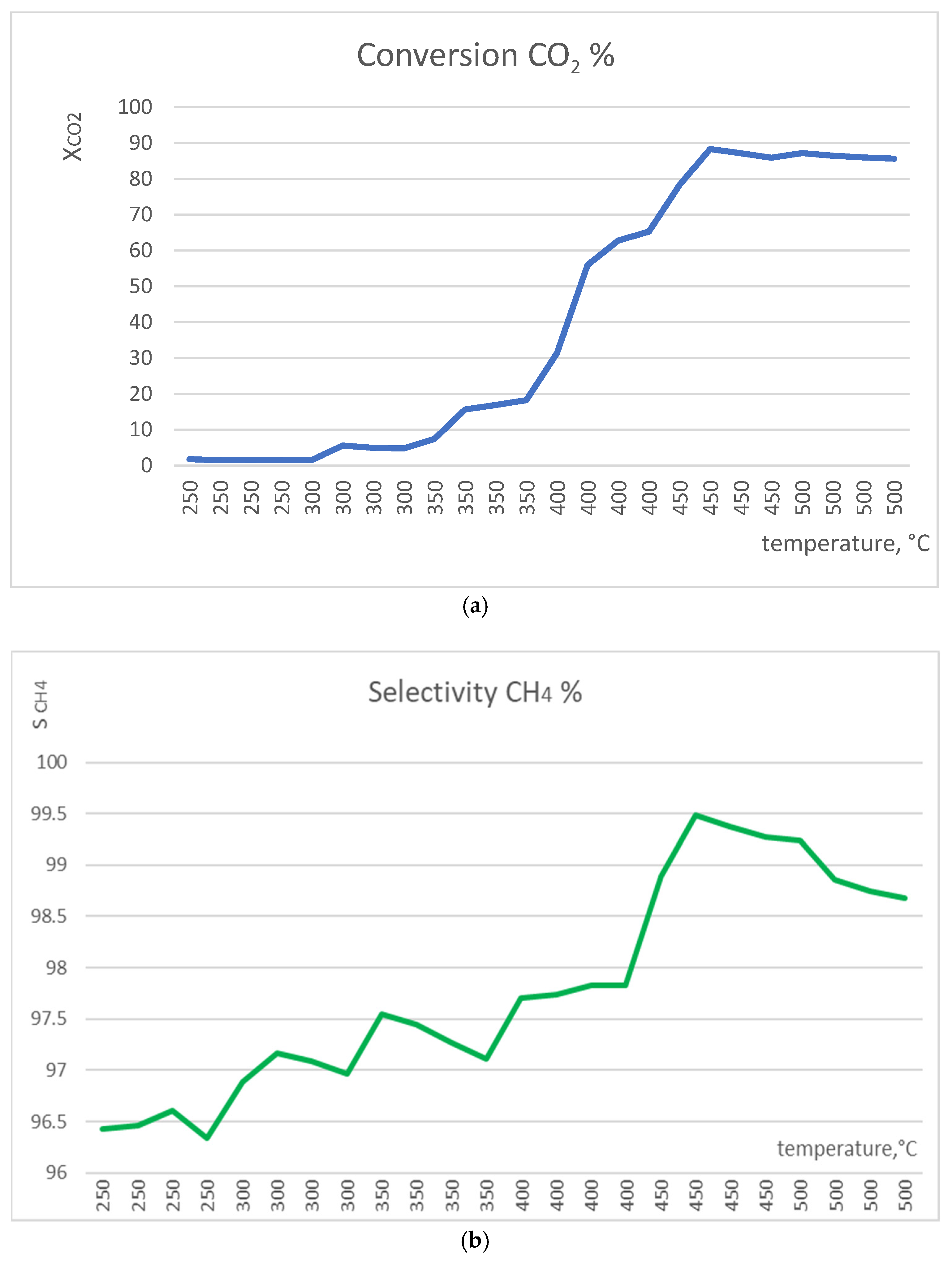
Figure 1. Test experiment: conversion CO2 (a) and selectivity CH4 (b) for NiOhx1 sample at temperature ramp from 250 up to 500 °C.
Molecules 29 04838 g001
Figure 2. TG/DSC graphs of nickel hydroxide (pre-NiOnd, before calcination).
Molecules 29 04838 g002
Figure 3. SEM images of NiO: NiOms1 (a), NiOms2 (b), NiOms3 (c), NiOshc (d), NiOhx1 (e), NiOhx2 (f), NiOhx+m (g), and NiO nd (h).
Molecules 29 04838 g003aMolecules 29 04838 g003b
Figure 4. SEM images of NiO samples after catalysis: NiOms2* (a), NiOms3* (b), NiOshc* (c), NiOhx2* (d), and NiOnd* (e). * Marking of the spent catalyst
Molecules 29 04838 g004
Figure 5. XPS (nickel 2p spectra) diagram of pre-catalysis samples: NiOhx1 (red), NiOms1 (green), and NiOhx+m (blue).
Molecules 29 04838 g005
Figure 6. XPS (survey spectra) diagram of pre-catalysis samples, NiOms1 (black), NiOhx1 (blue), and NiOhx+m (light blue), and post-catalysis samples, NiOms1* (red), NiOhx1* (green), and NiOhx+m* (light green).
Molecules 29 04838 g006
Figure 7. Temperature-programmed reduction (TPR-H2) spectrum measured with NiOhx2 sample (T = 25–600 °C).
Molecules 29 04838 g007
Figure 8. Temperature-programmed desorption (TPD-CO2) spectrum measured with NiOhx2 sample (T = 25–600 °C).
Molecules 29 04838 g008
Figure 9. Graphs of conversion CO2 ( x C O 2 ), selectivity CH4 ( s C H 4 ), reaction yield CH4 ( η C H 4 ), space–time yield ( S T Y C H 4 ), and selectivity CO (sco) of NiOhx1 (green), NiOhx2 (yellow), NiOhx+m (red), and NiOnd (grey).
Molecules 29 04838 g009
Figure 10. Graphs of conversion CO2 ( x C O 2 ), selectivity CH4 ( s C H 4 ), reaction yield CH4 ( η C H 4 ), space–time yield ( S T Y C H 4 ), and selectivity CO (sCO) of NiOms1 (purple), NiOms2 (light green), NiOms3 (red), and NiOshc (blue).
Molecules 29 04838 g010
Table 1. Summary table of synthesis conditions of prepared catalysts.
SampleAbbrev.Ni SaltSolventStabilizerTsynt,
°C
Tsynt, hTcalc, °CTcalc, h
NiO microspheres 1NiOms1Ni(Ac)2Met---20044502
NiO microspheres 2NiOms2Ni(NO3)2DMF---180124004
NiO microspheres 3NiOms3Ni(NO3)2DMF---
Ultrasound
180123504
NiO sheet clustersNiOshcNi(NO3)2EtOleylamine180153504
NiO hexagonal 1NiOhx1Ni(NO3)2Et + DWPVP 40,00018063502
NiO hexagonal 2NiOhx2Ni(NO3)2Et + DWPVP 360,00018063502
NiO hexagonal +
moon-like
NiOhx+mNi(NO3)2Et + DWPVP 40,00018063502
NiO nanodisk NiOndNi(Ac)2Et + DW---20084501
Tsynt, °C—solvothermal reaction temperature; tsynt, h—solvothermal reaction time; Tcalc, °C—calcination temperature of nickel hydroxide; tcalc, h—calcination time.
Table 2. Surface area and pore volume of NiO samples.
Sample NameNiOms1NiOms2NiOms3NiOshcNiOhx1NiOhx2NiOhx+mNiOnd
BET surface area, m2/g24.447.7110.3103.7145.5145.5128.955.5
Pore volume, cm3/g0.0490.1130.2020.1660.2210.1690.1620.123
Table 3. The content of elements on the surface of the catalyst before and after (*) catalysis.
SampleNi Ni #OO #CC #Si
NiOms1*1.22.039.321.646.476.513.2
NiOhx1*1.21.539.232.252.866.36.8
NiOhx111.0---35.7---53.4------
NiOms110.9---38.1---51.0------
NiOhx+m11.3---41.6---47.1------
NiOhx+m*1.62.643.929.341.568.013.1
All values are presented in atomic %. # denotes content of element after subtraction of SiO2 content in catalytic mixture.
Disclaimer/Publisher’s Note: The statements, opinions and data contained in all publications are solely those of the individual author(s) and contributor(s) and not of MDPI and/or the editor(s). MDPI and/or the editor(s) disclaim responsibility for any injury to people or property resulting from any ideas, methods, instructions or products referred to in the content.